Structures for Diversions and Channel Crossings, Irrigation Engineering | Irrigation Engineering Notes - Agricultural Engineering PDF Download
Water from the farm irrigation channel is diverted to branch channels or into field channels by means of junction boxes, and gates and siphons. These structures are used as water diversions structures or application structures for water application from irrigation channels of the fields. Brief description of these structures is given in this lesson.
14.1 Check Gates
The check gate is a structure used to maintain or increase water level in an open channel. Check is placed in an irrigation channel to form an adjustable dam to control or rise the elevation of the water surface upstream by at least about 8 to 12 cm above ground surface so as to use siphon tubes or turnouts for water diversion from channel to field efficiently. Fig. 14.1 shows the canal check gates. There may or may not be flow past a check. When there is no flow past them, checks act as dam that confine water release in the area along the canal or ditch being used for irrigation. Permanent check can be used in either lined or unlined channels. A check structure consists of canvas, metal or masonry walls built across the channel and provided with a suitable gate or outlet device. The masonry wall is built in place while the check gate is usually precast and fixed to the wall. The crest of the check gate is at the same level as the bottom of the upstream channel.
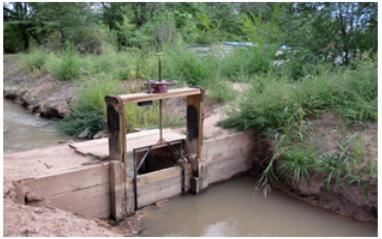
Fig. 14.1. Canal check gates
14.2 Portable Check Dams
Portable checks can be removed when irrigation is complete and reset at another location along the canal or open channel to irrigate another area. They are used when the water level in canals and ditches must be raised above the normal depth of flow to provide head for operating outlets. Portable check dams are made of sheet metal or plastic sheet or canvas. Canvas or plastic dams are supported on a pipe or wooden cross-bar with suitable loops. A loop is usually provided at the bottom to anchor the dam to a small post. A sleeve made near the bottom of a canvas dam allows any desired quantity of water to pass downstream, while maintaining a constant level upstream. In very hard soil it may be necessary to make grooves with the shovel to insert the edges. The canvas and plastic dams are removed after irrigation, properly washed, dried and stored in order to protect them and make usable for the next season. Metal sheet of about 18 gauge mild steel is cut to suit the channel cross section and driven at about 10 cm deep. Metal sheet has greater durability than other materials. Metal dams are always painted to prevent rusting (Michael, 2010).
14.3 Turnouts
Turnouts are constructed in the bank of a canal to divert part of the water from the canal and ditches to basins, borders, and distribution laterals. Turnouts can be concrete structures or pipe structures. A turnout may have a fixed opening in the side and equipped with the device to control the area of opening. They usually have removable flashboards or a circular or rectangular slide gate to regulate flow. Drop-open gates (similar to drop-open checks) are utilized in semiautomatic turnouts. Turnout commonly used is a metal pipe with slide gate on the inlet. The orifice flow formula is commonly used to determine the capacity of pipe turnout.
14.4 Siphon Tubes
Siphon tubes (Fig. 14.2) are curved plastic, rubber or aluminum pipes that are laid over the bank of delivery channels to deliver water to borders and furrows. The siphon tubes are completely filled and dipped in to water. Water flows into the tube, is pulled (siphoned) over the bank of the delivery channel, and delivered into borders and furrows when there is sufficient operating head and the tube is properly positioned and full of water (primed).For a free-flowing tube, the effective operational head is difference in elevation between the water surface at the tubes entrance and the center of its outlet end.
Siphon tubes are available in diameters ranging between 13 and 150 mm and length of 1.2 to 3.0 m. The discharge of a siphon tube depends on its diameter, length, and inside roughness the number and degree of bends and the operating head.
The discharge from a siphon tubes depend on the diameters of the tube and the difference in elevation between the water surface at the upstream and downstream ends of the tube. It may be estimated by the following formula: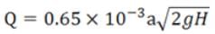
in which,
Q = discharge from siphon tube (L s-1)
a = internal area of cross-section of tube (cm2)
g = acceleration due to gravity (cm/sec2)
H = effective head causing flow (cm)
If the outlet is not submerged, the effective head is the vertical distance from the water level over the inlet end to the center of the discharge end.
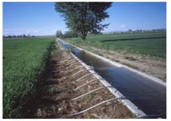
Fig.14.2. Siphon tubes.
14.5 Flumes
Flumes are constructed to carry irrigation water across streams, canals, gullies, ravines or other natural depressions. They may be open channels or pipes which are often supported by pillars or may be fixed to bridges. Open channels are made of concrete or wooden having rectangular or trapezoidal shapes. Alternative steel, concrete or vitrified clay pipes could also be used. However while using pipes, care should be taken to position them below the water surface at the upstream end to ensure that they are full. The supporting structure may be made of timber, steel or concrete. Manning’s equation is used to estimate discharge of the flumes. Flumes constructed in specially shaped and stabilized channel section may also be used to measure flow. Flumes are generally less inclined to catch floating debris and sediment than weirs and therefore, they are particularly suited for measurement of runoff.
14.6 Culverts
A culvert is a drain or pipe that allows water to flow under a road. Fig 14.3 Shows culvert pipes below a road. Culverts are most suitable structures at the channel crossing when the road fill is sufficiently high and the channel bed lies on the field surface on either side. About 45 cm soil cover is desired above the culvert pipe (Michael, 2010). The pipe used as a culvert has the simple function of providing passage for water underneath the path. The headwater elevation may be above or below the top of the inlet section. Solution of a culvert problem is primarily the determination of the type of flow that will occur under a given head and tail water conditions. Pipe flow (conduit controlling capacity) will occur under most conditions when the slope of the culvert is less than the natural slope and entrance capacity is not limiting. The natural slope for small angles of θ is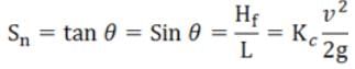
where,
Hf = friction loss in conduit of length L (L)
L = length of conduit (L)
Kc= friction loss coefficient (L/L)
v = velocity of flow (L/T)
g =acceleration due to gravity (L/T2)
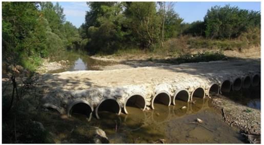
Fig. 14.3. Culverts.
14.7 Inverted Siphons
The inverted siphon (Fig. 14.4) is constructed when a channel has to cross a wide depression or where the road surface lies close to the field surface. It has an inlet and an outlet tank connected together at their bottom by a pipe. A check gate is used at the inlet end to control the water surface level in the upstream channel. The tank of an inverted siphon also acts as stilling basin. The bottom of the tanks is kept about 15-20 cm below the bottom of the pipe to collect the silt deposited due to slow down velocity of silt carrying water from upstream erosion.
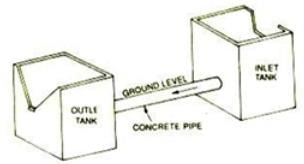
Fig. 14.4. Inverted siphons.

|
Dec 23, 2024 Last updated |
|
49 docs
|

|
Explore Courses for Agricultural Engineering exam
|
|
Objective type Questions
,MCQs
,Irrigation Engineering | Irrigation Engineering Notes - Agricultural Engineering
,Irrigation Engineering | Irrigation Engineering Notes - Agricultural Engineering
,ppt
,Sample Paper
,Exam
,study material
,video lectures
,Important questions
,Structures for Diversions and Channel Crossings
,Structures for Diversions and Channel Crossings
,Viva Questions
,Irrigation Engineering | Irrigation Engineering Notes - Agricultural Engineering
,Summary
,Structures for Diversions and Channel Crossings
,Semester Notes
,mock tests for examination
,Extra Questions
,shortcuts and tricks
,past year papers
,Free
,Previous Year Questions with Solutions
,practice quizzes
;


Structures for Diversions and Channel Crossings, Irrigation Engineering Free PDF Download
Importance of Structures for Diversions and Channel Crossings, Irrigation Engineering
Structures for Diversions and Channel Crossings, Irrigation Engineering Notes
Structures for Diversions and Channel Crossings, Irrigation Engineering Agricultural Engineering Questions
Study Structures for Diversions and Channel Crossings, Irrigation Engineering on the App
|
© EduRev
|
Education Revolution
|


|


