
Best Study Material for Electrical Engineering (EE) Exam
Electrical Engineering (EE) Exam > Electrical Engineering (EE) Notes > Network Theory (Electric Circuits) > Parallel Resonance
Parallel Resonance | Network Theory (Electric Circuits) - Electrical Engineering (EE) PDF Download
Parallel Resonance Circuit Diagram
If the resonance occurs in parallel RLC circuit, then it is called as Parallel Resonance. Consider the following parallel RLC circuit, which is represented in phasor domain.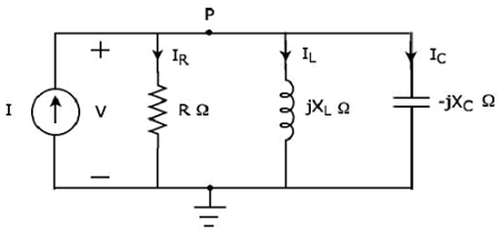
Here, the passive elements such as resistor, inductor and capacitor are connected in parallel. This entire combination is in parallel with the input sinusoidal current source.
Write nodal equation at node P.
−I + IR + IL + IC = 0
 Equation 1
The above equation is in the form of I = VY.
Therefore, the admittance Y of parallel RLC circuit will be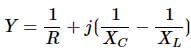
Parameters & Electrical Quantities at Resonance
Now, let us derive the values of parameters and electrical quantities at resonance of parallel RLC circuit one by one.
Resonant Frequency
We know that the resonant frequency, fr is the frequency at which, resonance occurs. In parallel RLC circuit resonance occurs, when the imaginary term of admittance, Y is zero. i.e., the value of  should be equal to zero
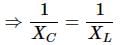
⇒ XL = XC
The above resonance condition is same as that of series RLC circuit. So, the resonant frequency, fr will be same in both series RLC circuit and parallel RLC circuit.
Therefore, the resonant frequency, fr of parallel RLC circuit is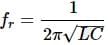
Where,
- L is the inductance of an inductor.
- C is the capacitance of a capacitor.
The resonant frequency, fr of parallel RLC circuit depends only on the inductance L and capacitance C. But, it is independent of resistance R.
Admittance
We got the admittance Y of parallel RLC circuit as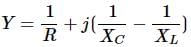
Substitute, XL = XC in the above equation.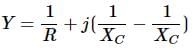
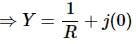
⇒ Y = 1/R
At resonance, the admittance, Y of parallel RLC circuit is equal to the reciprocal of the resistance, R. i.e., Y = 1/R
Voltage across each Element
Substitute, 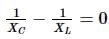 in Equation 1
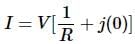
⇒ I = VR
⇒ V = IR
Therefore, the voltage across all the elements of parallel RLC circuit at resonance is V = IR.
At resonance, the admittance of parallel RLC circuit reaches to minimum value. Hence, maximum voltage is present across each element of this circuit at resonance.
Current flowing through Resistor
The current flowing through resistor is
IR = V/R
⇒ IR = I
Therefore, the current flowing through resistor at resonance is IR = I.
Current flowing through Inductor
The current flowing through inductor is
Substitute the value of V in the above equation.
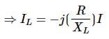
⇒IL = −jQI
Therefore, the current flowing through inductor at resonance is IL = −jQI.
So, the magnitude of current flowing through inductor at resonance will be
|IL| = QI
Where, Q is the Quality factor and its value is equal to
Current flowing through Capacitor
The current flowing through capacitor is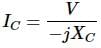
Substitute the value of V in the above equation.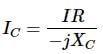
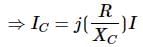
⇒ IC = jQI
Therefore, the current flowing through capacitor at resonance is IC = jQI
So, the magnitude of current flowing through capacitor at resonance will be
|IC|=QI
Where, Q is the Quality factor and its value is equal to
Note − Parallel resonance RLC circuit is called as current magnification circuit. Because, the magnitude of current flowing through inductor and capacitor is equal to Q times the input sinusoidal current I.
The document Parallel Resonance | Network Theory (Electric Circuits) - Electrical Engineering (EE) is a part of the Electrical Engineering (EE) Course Network Theory (Electric Circuits).
All you need of Electrical Engineering (EE) at this link: Electrical Engineering (EE)
|
73 videos|102 docs|62 tests
|


FAQs on Parallel Resonance - Network Theory (Electric Circuits) - Electrical Engineering (EE)
| 1. What is parallel resonance in electrical engineering? |  |
| 2. How does parallel resonance affect the voltage across the circuit? | |
Ans. In parallel resonance, the voltage across the circuit is maximum. This is because the impedance of the circuit is at its minimum, causing the current to be at its peak. As a result, the voltage drop across the inductor and capacitor is minimized, leading to a higher voltage across the entire circuit.
| 3. What are the applications of parallel resonance in electrical engineering? | |
Ans. Parallel resonance has various applications in electrical engineering. It is commonly used in power factor correction circuits, where it helps to compensate for reactive power and improve overall power efficiency. It is also utilized in filter circuits, where it allows for the selective passage of certain frequencies while attenuating others.
| 4. How can parallel resonance be used in wireless communication systems? | |
Ans. Parallel resonance can be employed in wireless communication systems for frequency selection and tuning. By designing the circuit to resonate at a specific frequency, it becomes highly sensitive to signals at that frequency, allowing for efficient reception and transmission. This technique is commonly used in radio and television receivers.
| 5. What are the potential drawbacks of parallel resonance in electrical circuits? | |
Ans. While parallel resonance can be advantageous, it also poses certain challenges. One drawback is the potential for high circulating currents in the circuit, which can lead to power losses and overheating. Additionally, the circuit's sensitivity to frequency variations can cause instability and affect its performance. Proper design and control measures are necessary to mitigate these issues.
About this Document

4.61/5
Rating

Apr 22, 2025
Last updated
Document Description: Parallel Resonance for Electrical Engineering (EE) 2025 is part of Network Theory (Electric Circuits) preparation.
The notes and questions for Parallel Resonance have been prepared according to the Electrical Engineering (EE) exam syllabus. Information about Parallel Resonance covers topics
like and Parallel Resonance Example, for Electrical Engineering (EE) 2025 Exam. Find important definitions, questions, notes, meanings, examples, exercises and tests below for Parallel Resonance.
Introduction of Parallel Resonance in English is available as part of our Network Theory (Electric Circuits)
for Electrical Engineering (EE) & Parallel Resonance in Hindi for Network Theory (Electric Circuits) course.
Download more important topics related with notes, lectures and mock test series for Electrical Engineering (EE)
Exam by signing up for free. Electrical Engineering (EE): Parallel Resonance | Network Theory (Electric Circuits) - Electrical Engineering (EE)
Description
Full syllabus notes, lecture & questions for Parallel Resonance | Network Theory (Electric Circuits) - Electrical Engineering (EE) - Electrical Engineering (EE) | Plus excerises question with solution to help you revise complete syllabus for Network Theory (Electric Circuits) | Best notes, free PDF download
Information about Parallel Resonance
In this doc you can find the meaning of Parallel Resonance defined & explained in the simplest way possible. Besides explaining types of
Parallel Resonance theory, EduRev gives you an ample number of questions to practice Parallel Resonance tests, examples and also practice Electrical Engineering (EE)
tests

Related Searches
Parallel Resonance | Network Theory (Electric Circuits) - Electrical Engineering (EE)
,ppt
,Sample Paper
,shortcuts and tricks
,Semester Notes
,Parallel Resonance | Network Theory (Electric Circuits) - Electrical Engineering (EE)
,Previous Year Questions with Solutions
,Exam
,Objective type Questions
,Important questions
,Viva Questions
,video lectures
,Summary
,practice quizzes
,mock tests for examination
,study material
,Free
,past year papers
,MCQs
,Parallel Resonance | Network Theory (Electric Circuits) - Electrical Engineering (EE)
,Extra Questions
;


Additional Information about Parallel Resonance for Electrical Engineering (EE) Preparation
Parallel Resonance Free PDF Download
The Parallel Resonance is an invaluable resource that delves deep into the core of the Electrical Engineering (EE) exam.
These study notes are curated by experts and cover all the essential topics and concepts, making your preparation more efficient and effective.
With the help of these notes, you can grasp complex subjects quickly, revise important points easily,
and reinforce your understanding of key concepts. The study notes are presented in a concise and easy-to-understand manner,
allowing you to optimize your learning process. Whether you're looking for best-recommended books, sample papers, study material,
or toppers' notes, this PDF has got you covered. Download the Parallel Resonance now and kickstart your journey towards success in the Electrical Engineering (EE) exam.
Importance of Parallel Resonance
The importance of Parallel Resonance cannot be overstated, especially for Electrical Engineering (EE) aspirants.
This document holds the key to success in the Electrical Engineering (EE) exam.
It offers a detailed understanding of the concept, providing invaluable insights into the topic.
By knowing the concepts well in advance, students can plan their preparation effectively.
Utilize this indispensable guide for a well-rounded preparation and achieve your desired results.
Parallel Resonance Notes
Parallel Resonance Notes offer in-depth insights into the specific topic to help you master it with ease.
This comprehensive document covers all aspects related to Parallel Resonance.
It includes detailed information about the exam syllabus, recommended books, and study materials for a well-rounded preparation.
Practice papers and question papers enable you to assess your progress effectively.
Additionally, the paper analysis provides valuable tips for tackling the exam strategically.
Access to Toppers' notes gives you an edge in understanding complex concepts.
Whether you're a beginner or aiming for advanced proficiency, Parallel Resonance Notes on EduRev are your ultimate resource for success.
Parallel Resonance Electrical Engineering (EE) Questions
The "Parallel Resonance Electrical Engineering (EE) Questions" guide is a valuable resource for all aspiring students preparing for the
Electrical Engineering (EE) exam. It focuses on providing a wide range of practice questions to help students gauge
their understanding of the exam topics. These questions cover the entire syllabus, ensuring comprehensive preparation.
The guide includes previous years' question papers for students to familiarize themselves with the exam's format and difficulty level.
Additionally, it offers subject-specific question banks, allowing students to focus on weak areas and improve their performance.
Study Parallel Resonance on the App
Students of Electrical Engineering (EE) can study Parallel Resonance alongwith tests & analysis from the EduRev app,
which will help them while preparing for their exam. Apart from the Parallel Resonance,
students can also utilize the EduRev App for other study materials such as previous year question papers, syllabus, important questions, etc.
The EduRev App will make your learning easier as you can access it from anywhere you want.
The content of Parallel Resonance is prepared as per the latest Electrical Engineering (EE) syllabus.
|
© EduRev
|
Education Revolution
|


|


Signup on EduRev and stay on top of your study goals
10M+ students crushing their study goals daily