Coupled Circuits | GATE Notes & Videos for Electrical Engineering - Electrical Engineering (EE) PDF Download

Dot Convention
Dot convention is a technique, which gives the details about voltage polarity at the dotted terminal. This information is useful, while writing KVL equations.

  • If the current enters at the dotted terminal of one coil (or inductor), then it induces a voltage at another coil (or inductor), which is having positive polarity at the dotted terminal.
  • If the current leaves from the dotted terminal of one coil (or inductor), then it induces a voltage at another coil (or inductor), which is having negative polarity at the dotted terminal.

Classification of Coupling
We can classify coupling into the following two categories.

  • Electrical Coupling
  • Magnetic Coupling

Now, let us discuss about each type of coupling one by one.

Electrical Coupling
Electrical coupling occurs, when there exists a physical connection between two coils (or inductors). This coupling can be of either aiding type or opposing type. It is based on whether the current enters at the dotted terminal or leaves from the dotted terminal.

Coupling of Aiding type
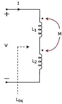
Consider the following electric circuit, which is having two inductors that are connected in series.
Coupled Circuits | GATE Notes & Videos for Electrical Engineering - Electrical Engineering (EE)
Since the two inductors are connected in series, the same current I flow through both inductors having self-inductances L1 and L2.
In this case, the current, I enter at the dotted terminal of each inductor. Hence, the induced voltage in each inductor will be having positive polarity at the dotted terminal due to the current flowing in another coil.
Apply KVL around the loop of the above electric circuit or network.
Coupled Circuits | GATE Notes & Videos for Electrical Engineering - Electrical Engineering (EE)
The above equation is in the form of Coupled Circuits | GATE Notes & Videos for Electrical Engineering - Electrical Engineering (EE)
Therefore, the equivalent inductance of series combination of inductors shown in the above figure is LEq = L1 + L2 + 2M
In this case, the equivalent inductance has been increased by 2M. Hence, the above electrical circuit is an example of electrical coupling which is of aiding type.

Coupling of Opposing type
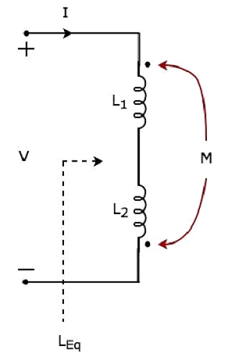
Consider the following electric circuit, which is having two inductors that are connected in series.
Coupled Circuits | GATE Notes & Videos for Electrical Engineering - Electrical Engineering (EE)
In the above circuit, the current I enters at the dotted terminal of the inductor having an inductance of L1. Hence, it induces a voltage in the other inductor having an inductance of L2. So, positive polarity of the induced voltage is present at the dotted terminal of this inductor.
In the above circuit, the current I leaves from the dotted terminal of the inductor having an inductance of L2. Hence, it induces a voltage in the other inductor having an inductance of L1. So, negative polarity of the induced voltage is present at the dotted terminal of this inductor.
Apply KVL around the loop of the above electric circuit or network.
Coupled Circuits | GATE Notes & Videos for Electrical Engineering - Electrical Engineering (EE)
The above equation is in the form of Coupled Circuits | GATE Notes & Videos for Electrical Engineering - Electrical Engineering (EE)
Therefore, the equivalent inductance of series combination of inductors shown in the above figure is
LEq = L1 + L2 − 2M
In this case, the equivalent inductance has been decreased by 2M. Hence, the above electrical circuit is an example of electrical coupling which is of opposing type.

Magnetic Coupling
Magnetic coupling occurs, when there is no physical connection between two coils (or inductors). This coupling can be of either aiding type or opposing type. It is based on whether the current enters at the dotted terminal or leaves from the dotted terminal.

Coupling of Aiding type
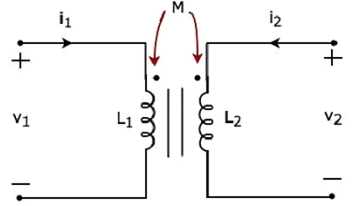
Consider the following electrical equivalent circuit of transformer. It is having two coils and these are called as primary and secondary coils.
Coupled Circuits | GATE Notes & Videos for Electrical Engineering - Electrical Engineering (EE)
The currents flowing through primary and secondary coils are i1 and i2 respectively. In this case, these currents enter at the dotted terminal of respective coil. Hence, the induced voltage in each coil will be having positive polarity at the dotted terminal due to the current flowing in another coil.
Apply KVL around primary coil.
Coupled Circuits | GATE Notes & Videos for Electrical Engineering - Electrical Engineering (EE)
Apply KVL around secondary coil.
Coupled Circuits | GATE Notes & Videos for Electrical Engineering - Electrical Engineering (EE)
In Equation 1 and Equation 2, the self-induced voltage and mutually induced voltage have the same polarity. Hence, the above transformer circuit is an example of magnetic coupling, which is of aiding type.

Coupling of Opposing Type
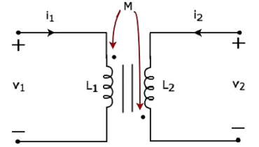
Consider the following electrical equivalent circuit of transformer.
Coupled Circuits | GATE Notes & Videos for Electrical Engineering - Electrical Engineering (EE)
The currents flowing through primary and secondary coils are i1 and i2 respectively. In this case, the current, i1 enters at the dotted terminal of primary coil. Hence, it induces a voltage in secondary coil. So, positive polarity of the induced voltage is present at the dotted terminal of this secondary coil.
In the above circuit, the current, i2 leaves from the dotted terminal of secondary coil. Hence, it induces a voltage in primary coil. So, negative polarity of the induced voltage is present at the dotted terminal of this primary coil.
Apply KVL around primary coil.
Coupled Circuits | GATE Notes & Videos for Electrical Engineering - Electrical Engineering (EE)
Apply KVL around secondary coil.
Coupled Circuits | GATE Notes & Videos for Electrical Engineering - Electrical Engineering (EE)
In Equation 3 and Equation 4, self-induced voltage and mutually induced voltage are having opposite polarity. Hence, the above transformer circuit is an example of magnetic coupling, which is of opposing type.

The document Coupled Circuits | GATE Notes & Videos for Electrical Engineering - Electrical Engineering (EE) is a part of the Electrical Engineering (EE) Course GATE Notes & Videos for Electrical Engineering.
All you need of Electrical Engineering (EE) at this link: Electrical Engineering (EE)
27 videos|328 docs

Top Courses for Electrical Engineering (EE)

FAQs on Coupled Circuits - GATE Notes & Videos for Electrical Engineering - Electrical Engineering (EE)

1. What are coupled circuits?
Coupled circuits refer to a system of interconnected circuits that share a mutual magnetic or electromagnetic field. This coupling allows energy transfer between the circuits and affects their behavior.
2. How does the coupling between circuits impact their behavior?
The coupling between circuits can impact their behavior in several ways. It can cause mutual inductance, where the changing magnetic field in one circuit induces a voltage in the other circuit. This can lead to changes in the circuit's impedance, resonance frequency, and overall performance.
3. What is the significance of resonance frequency in coupled circuits?
Resonance frequency plays a crucial role in coupled circuits. When the resonance frequency of one circuit matches the natural frequency of another, energy transfer between the circuits is maximized. This can be utilized in applications such as wireless power transfer and communication systems.
4. How can coupled circuits be analyzed?
Coupled circuits can be analyzed using techniques such as the concept of equivalent circuits and the coupled inductor model. These methods allow engineers to calculate parameters like the coupling coefficient, mutual inductance, and transfer function, enabling a deeper understanding of the behavior of the coupled circuits.
5. What are some practical applications of coupled circuits?
Coupled circuits find applications in various fields. They are commonly used in transformers for power distribution, where energy is transferred between primary and secondary windings through magnetic coupling. Coupled circuits are also employed in wireless communication systems, wireless power transfer, and resonant circuits used in radio frequency identification (RFID) technology.
Explore Courses for Electrical Engineering (EE) exam

Top Courses for Electrical Engineering (EE)

Signup for Free!
Signup to see your scores go up within 7 days! Learn & Practice with 1000+ FREE Notes, Videos & Tests.
10M+ students study on EduRev
Related Searches

Free

,

Coupled Circuits | GATE Notes & Videos for Electrical Engineering - Electrical Engineering (EE)

,

mock tests for examination

,

Previous Year Questions with Solutions

,

Exam

,

ppt

,

Important questions

,

MCQs

,

Summary

,

study material

,

Extra Questions

,

shortcuts and tricks

,

Semester Notes

,

Coupled Circuits | GATE Notes & Videos for Electrical Engineering - Electrical Engineering (EE)

,

Objective type Questions

,

Sample Paper

,

practice quizzes

,

pdf

,

video lectures

,

Viva Questions

,

past year papers

,

Coupled Circuits | GATE Notes & Videos for Electrical Engineering - Electrical Engineering (EE)

;