Past Year Questions: Methods of Structural Analysis | Topic wise GATE Past Year Papers for Civil Engineering - Civil Engineering (CE) PDF Download
Q1: In the frame shown in the figure (not to scale), all four members (AB,BC,CD, and AD ) have the same length and same constant flexural rigidity. All the joints A,B,C, and D are rigid joints. The midpoints of AB,BC,CD, and AD, are denoted by E,F,G, and H, respectively. The frame is in unstable equilibrium under the shown forces of magnitude P acting at E and G. Which of the following statements is/are TRUE? [2023, Set-2]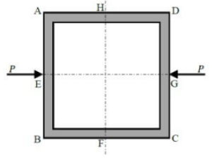 (a) Shear forces at H and F are zero
(b) Horizontal displacement at H and F are zero
(c) Vertical displacement at H and F are zero
(d) Slopes at E, F, G, and H are zero
Ans: (a, b and d)
Sol: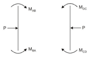
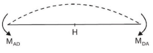
 Due to symmetry horizontal displacement of H & F = zero
⇒ option (B) correct
Also due to symmetry slopes at E, F, G, H = 0 ⇒ option (D) is correct
Since AD and BC are subjected to pure bending Hence shear force at H&F are zero
⇒ option (A) correct
Vertical displacement at H & F ≠ 0
⇒ option (C) is incorrect.
Q1: The linearly elastic planar structure shown in the figure is acted upon by two vertical concentrated forces. The horizontal beams UV and WX are connected with the help of the vertical linear spring with spring constant k=20kN/m. The fixed supports are provided at U and X. It is given that flexural rigidity EI = 105kN - m2, P = 100kN, and a = 5 m. Force Q is applied at the center of beam WX such that the force in the spring VW becomes zero. [2022, Set-2]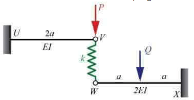 The magnitude of force Q (in kN) is ________. (round off to the nearest integer)
Ans: 620 to 660
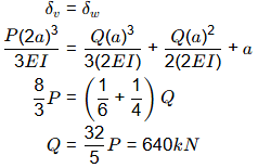
Sol: If force in spring is zero, there will be no deformation in spring i.e., deflection of point V will be equal to deflection of point W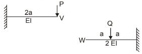
Q2: Which of the following statement(s) is/are correct? [2022, Set-2]
(a) If a linearly elastic structure is subjected to a set of loads, the partial derivative of the total strain energy with respect to the deflection at any point is equal to the load applied at that point.
(b) If a linearly elastic structure is subjected to a set of loads, the partial derivative of the total strain energy with respect to the load at any point is equal to the deflection at that point.
(c) If a structure is acted upon by two force system Pa and Pb, in equilibrium separately, the external virtual work done by a system of forces Pb during the deformations caused by another system of forces Pa is equal to the external virtual work done by the Pa system during the deformation caused by the Pb system.
(d) The shear force in a conjugate beam loaded by the M/El diagram of the real beam is equal to the corresponding deflection of the real beam.
Ans: (a, b and c)
Q3: Consider the linearly elastic plane frame shown in the figure. Members HF, FK and FG are welded together at joint F. Joints K, G and H are fixed supports. A counter-clockwise moment M is applied at joint F. Consider flexural rigidity El = 105kN-m2 for each member and neglect axial deformations.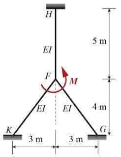 If the magnitude (absolute value) of the support moment at H is 10 kN-m, the magnitude (absolute value) of the applied moment M (in kN-m) to maintain static equilibrium is ___________. (round off to the nearest integer) [2022, Set-1]
Ans: 57 to 63
Sol: M/ 6 = 10kNm ⇒ M = 60kNm
Q1: A frame EFG is shown in the figure. All members are prismatic and have equal flexural rigidity. The member FG carries a uniformly distributed load w per unit length. Axial deformation of any member is neglected. [2021, Set-2]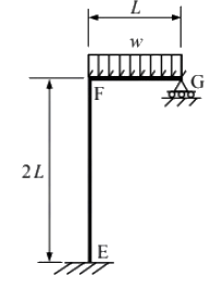 Considering the joint F being rigid, the support reaction at G is
(a) 0.375 wL
(b) 0.453 wL
(c) 0.482 wL
(d) 0.500 wL
Ans: (c)
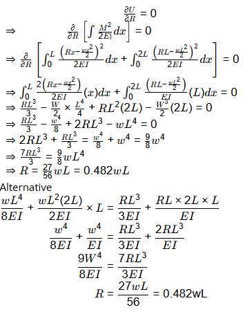
Sol: Compatibility condition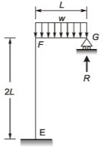
Q2: A propped cantilever beam XY, with an internal hinge at the middle, is carrying a uniformly distributed load of 10 kN/m, as shown in the figure. [2021, Set-2]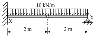 The vertical reaction at support X ( in kN, in integer) is _____
Ans: 30
Sol:
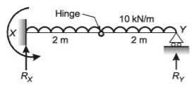 BM = 0 at hinge
RY × 2 - 10 × 2 × 1 = 0
RY = 10kN
RX + RY = 10 × 4
RX + 10 = 40
RX = 30kN
Q1: The planar structure RST shown in the figure is roller-supported at S and pin-supported at R. Members RS and ST have uniform flexural rigidity (EI) and S is a rigid joint. Consider only bending deformation and neglect effects of self-weight and axial stiffening [2020, Set-2]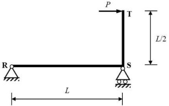 When the structure is subjected to a concentrated horizontal load P at the end T, the magnitude of rotation at the support R, is
(a)
(b)
(c)
(d)
Ans: (b)
Sol: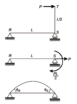

Q2: A prismatic linearly elastic bar of length, L, cross-sectional area A and made up of a material with Young's modulus E, is subjected to axial tensile force as shown in the figures. When the bar is subjected to axial tensile force P1 and P2, the strain energies stored in the bar are U1 and U2, respectively. [2020, Set-2]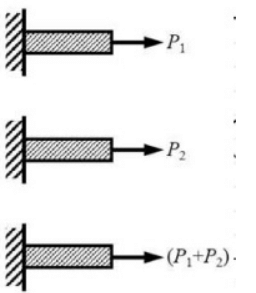
If U is the strain energy stored in the same bar when subjected to an axial tensile force (P1 + P2 ), the correct relationship is
(a) U = U1 + U2
(b) U = U1 - U2
(c) U < U1 + U2
(d) U > U1 + U2
Ans: (d)
Sol: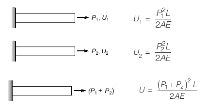
(P1 + P2)2 > P21 + P22 U > U1 + U2
Q1: A portal frame shown in figure (not drawn to scale) has a hinge support at joint P and a roller support at joint R. A point load of 50 kN is acting at joint R in the horizontal direction. The flexural rigidity. El, of each member is 106 kNm2. Under the applied load, the horizontal displacement (in mm, round off to 1 decimal place) of joint R would be______. [2019, Set-1]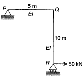
Ans: 24.9 to 25.1
Sol:
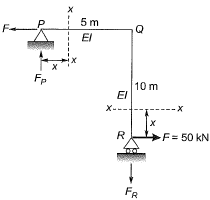
ΣMp = 0 [Take clockwise as positive]
RR × 5 - 50 × 10 = 0
RR = -100kN (↓)
RP = 100kN (↑)
EI = 106kN - m2

where
Mx = BM at X - X due to real loads
mx = BM at X - X due to vertical unit load applied where we want to find the deflection.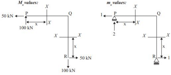
ΣMR = 0 [Take clockwise as positive]
RP × 5 - 1 × 10 = 0
RP = 2kN (↑)
Sign conventions:
Sagging +ve
Hogging -ve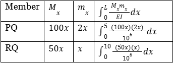

Q2: The rigid-jointed plane frame QRS shown in figure is subjected to load P at the joint R. Let the axial deformations in the frame be neglected. If the support S undergoes a settlement of  the vertical reaction at the support S will be become zero when β is equal to [2019, Set-1]
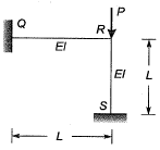
(a) 7.5
(b) 3
(c) 48
(d) 0.1
Ans: (a)
Sol:
Adopting moment distribution method:
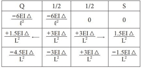 Thus, final vertical reaction at S (both due f0 sinking and )
RS = P - V

Q1: A prismatic beam P-Q-R of flexural rigidity El = 1 x 10⁴ kNm2 is subjected to a moment of 180 kNm at Q as shown in the figure.
The rotation at Q (in rad, up to two decimal places) is ________ . [2018, Set-2]
Ans:0.01
Sol:

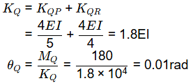
Alternate solution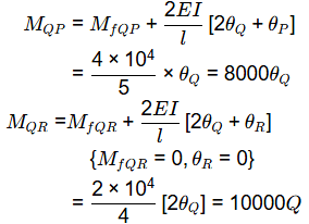
ΣMQ = 0
⇒ MQP + MQR + 180 = 0
⇒ 18000 . θQ = -180
⇒ θQ = 0.01 radian (anticlockwise)
Q2: A vertical load of 10 kN acts on a hinge located at a distance of LI4 from the roller support Q of a beam of length L (see figure). [2018, Set-2]
The vertical reaction at support Q is
(a) 0.0 kN
(b) 2.5 kN
(c) 7.5 kN
(d) 10.0 kN
Ans: (a)
Sol:

Bending moment about hinge point A = 0
(consider the right hand side of A)

Q1: Consider the portal frame shown in the figure and assume the modulus of elasticity, E = 2.5 x 10⁴ MPa and the moment of inertia, I = 8 x 108 mm4 for all the members of the frame.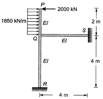
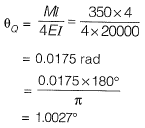
The rotation (in degrees, up to one decimal place) at the rigid joint Q would b e _________ . [2017 : 2 Marks, Set-II)
Sol:
Method-I
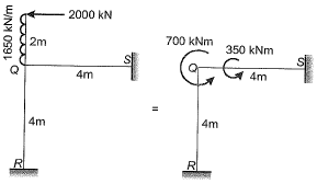

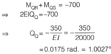
= -700 kNm (ACW)
EI = 2.5 x 104 x 8 x 108
= 20 x 1012 Nmm2
= 20000 kNm2
As the two members QR and QS are identical, moment will be equally divided i.e., 350 kNm each.
Method-ll
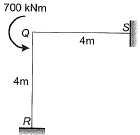
Fixed end moment:

Slope deflection equation:

Joint equilibrium equation at joint Q,
Q6: The value of M in the beam ABC shown in the figure is such that the joint B does not rotate.
The value of support reaction (in kN) at B should be equal to ________. [2017 : 2 Marks, Set-I]
Solution:
Method-I
Fixed end moment:

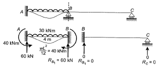
By super position,

Note : The value of 'M' shown in the figure,

Q.7 The portal frame shown in the figure is subjected to a uniformly distributed vertical load w(per unit length).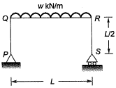
The bending moment in the beam at the join ‘Q ’ is [2016 : 2 Marks, Set-II]
(a) zero
(b) 
(c) 
(d) 
Ans. (A)
Solution:
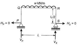
As there is no horizontal force,
Hence,
HP = HS = 0

∴ BM at Q = 0
Q.8 For the beam shown below, the value of the support moment M is ____ kN-m. [2015 : 1 Mark, Set-I]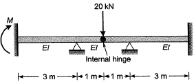
Solution:
By symmetry we can consider two parts of beam separately with half the load.

Moment at joint B = 10 kNm
Carry over moment at joint A due to 10 kNm moment at propped end = 10/2= 5kN-m
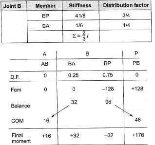
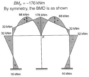
Q.9 Considering the symmetry of a rigid frame as shown below, the magnitude of the bending moment (in kNm) at P (preferably using the moment distribution method) is [2014 : 2 Marks, Set-II]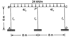
(a) 170
(b) 172
(c) 176
(d) 178
Ans. (C)
Solution:
As the frame and loading is symmetrical, θP= 0. So, joint Pcan be replaced by a fixed support as shown.
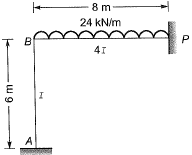
Fixed end moment:
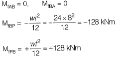
Distribution factor:
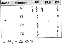
Q.10 All members in the rigid-jointed frame shown are prismatic and have the same flexural stiffness EI. Find the magnitude of BM at Q (in kN-m) due to given loading. [2013 : 2 Marks]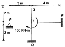
Solution: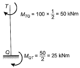
FAQs on Past Year Questions: Methods of Structural Analysis - Topic wise GATE Past Year Papers for Civil Engineering - Civil Engineering (CE)
| 1. What are the common methods used in structural analysis? |  |
| 2. How does the finite element method work in structural analysis? |  |
| 3. What is the significance of load combinations in structural analysis? |  |
| 4. What are the advantages of using computer software for structural analysis? |  |
| 5. How do you determine the stability of a structure in structural analysis? |  |


