Previous Year Questions 2025
Q1: Two statements are given - one labelled as Assertion (A) and the other labelled as Reason (R). Select the correct answer to these questions from the codes (A), (B), (C) and (D) as given below : (1 Mark)
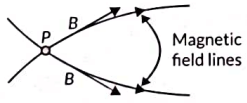
Assertion (A): No two magnetic field lines are found to cross each other.
Reason (R): The compass needle cannot point towards two directions at the point of intersection of two magnetic field lines.
(a) Both A and R are true, and R is the correct explanation of A.
(b) Both A and R are true, but R is not the correct explanation of A.
(c) A is true, but R is false.
(d) A is false, but R is true.
 View Answer
Ans: (A) Both A and R are true, and R is the correct explanation of A.
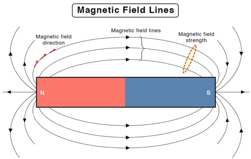
- Assertion (A): Magnetic field lines represent the direction and strength of the magnetic field. They never cross each other because at any point in space, the magnetic field has a unique direction. If two field lines crossed, it would imply two different directions for the magnetic field at that point, which is physically impossible. Thus, A is true.
- Reason (R): A compass needle aligns itself along the magnetic field direction at a given point. If field lines intersected, the needle would have to point in two directions simultaneously, which is not possible. This explains why magnetic field lines do not cross. Thus, R is true and correctly explains A.
- Conclusion: Option (A) is correct.
Q2: Two statements are given - one labelled as Assertion (A) and the other labelled as Reason (R). Select the correct answer to these questions from the codes (A), (B), (C) and (D) as given below : (1 Mark)
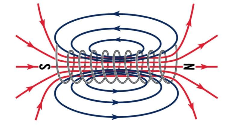
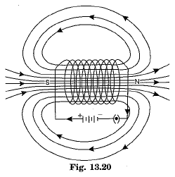
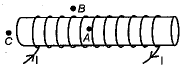
Assertion (A): The pattern of the magnetic field of a solenoid carrying a current is similar to that of a bar magnet.
Reason (R): The pattern of the magnetic field around a current-carrying conductor is independent of the shape of the conductor.
(a) Both A and R are true, and R is the correct explanation of A.
(b) Both A and R are true, but R is not the correct explanation of A.
(c) A is true, but R is false.
(d) A is false, but R is true.
View Answer Ans: (C) A is true, but R is false.
- Assertion (A): A current-carrying solenoid produces a magnetic field similar to that of a bar magnet, with one end acting as the north pole and the other as the south pole. The field lines emerge from one end (north) and enter the other (south), resembling a bar magnet’s field. Thus, A is true.
- Reason (R): The magnetic field pattern around a current-carrying conductor depends on its shape. For example, a straight conductor produces concentric circular field lines, while a solenoid produces a bar magnet-like field. Thus, R is false as the field pattern is shape-dependent.
- Conclusion: Option (C) is correct, as A is true, but R is false and does not explain A.
Q3: Which one of the following statements is not true about a bar magnet? (1 Mark)
(a) It sets itself in north-south direction when suspended freely.
(b) It has attractive power for iron filings.
(c) It produces magnetic field lines.
(d) The direction of magnetic field lines inside a bar magnet is from its north pole to its south pole.
View Answer Ans: (d) The direction of magnetic field lines inside a bar magnet is from its north pole to its south pole.
- Option (A): True. A freely suspended bar magnet aligns itself in the north-south direction due to Earth’s magnetic field, with its north pole pointing toward the geographic north.
- Option (B): True. A bar magnet attracts ferromagnetic materials like iron filings due to its magnetic field.
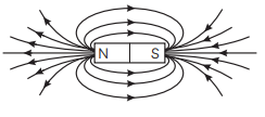
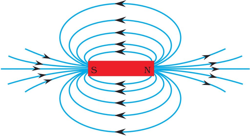
- Option (C): True. A bar magnet produces magnetic field lines that emerge from the north pole and enter the south pole, forming closed loops.
- Option (D): False. By convention, magnetic field lines outside a bar magnet go from the north pole to the south pole, but inside the magnet, they travel from the south pole to the north pole to form continuous loops.
- Conclusion: Option (D) is not true.
Q4: The strength of the magnetic field produced inside a long straight current-carrying solenoid does not depend upon: (1 Mark)
(A) Number of turns in the solenoid
(B) Direction of current flowing through the solenoid
(C) Material of the core filled inside the solenoid
(D) Magnitude of current in the solenoid
View Answer Ans: (B) Direction of current flowing through the solenoid
For a long current-carrying solenoid, the magnetic field inside is
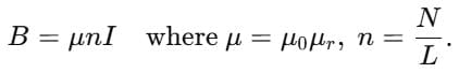 Hence, B depends on:
Number of turns per unit length n (more turns → stronger field),
Core material via μr (e.g., iron increases B),
Magnitude of current I (largerI → larger B).
Changing the direction of current only reverses the polarity (which end is north/south) but does not change the magnitude of B.
Therefore, the strength of the magnetic field does not depend on the direction of current. (Option B).
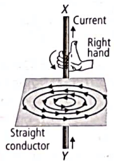
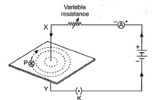
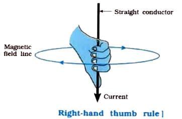
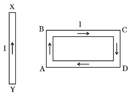
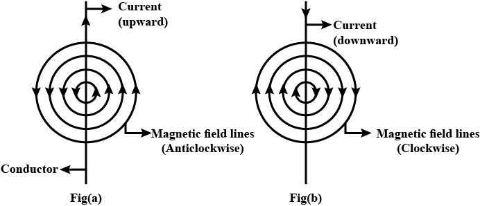
Q5: (i) The given figure shows the current passing through the straight conductor XY.
 (ii) Name and state the rule used in determining the direction of the magnetic field lines in the situation given above.
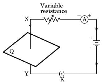
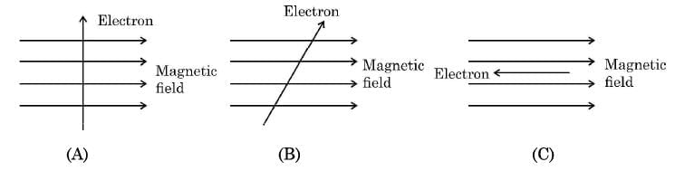
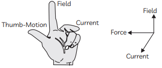
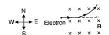
(iii) State Fleming’s left-hand rule. Using this rule, determine the direction of force applied on an electron entering a uniform magnetic field as shown in the figure. (5 Marks)
View Answer Ans:
i) Magnetic Field Lines Due to Current in Conductor XY
When current flows from X to Y in the straight conductor XY, the magnetic field around the wire consists of concentric circles centred on the wire.
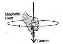
By the Right-hand thumb rule (thumb along current X→Y; curled fingers give field direction), the field is clockwise around the wire as seen from the X→Y end.
ii) Rule Used to Determine Magnetic Field Direction
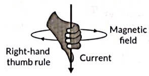
Rule Name: Right-Hand Thumb Rule (Maxwell's Corkscrew Rule)
Statement: If you hold a straight conductor in your right hand so that your thumb points in the direction of current, the direction in which your fingers wrap around the conductor gives the direction of the magnetic field lines.
iii) Fleming's Left Hand Rule and Direction of Force on Electron
Fleming's Left Hand Rule Statement: Stretch the thumb, forefinger, and middle finger of your left hand mutually perpendicular to each other. If the forefinger points in the direction of the magnetic field, the middle finger in the direction of current (conventional, positive to negative), then the thumb gives the direction of force (motion) on the conductor.
Magnetic field: to the right.
Electron velocity: upwards ⇒ conventional current is downwards.
Set forefinger → right (B), middle finger → down (I).
Thumb then points out of the plane of the paper (towards the observer).
Therefore, the force on the electron is out of the page, perpendicular to both  (For a positive charge it would be into the page.)
Q6: (a) Name and state the rule which determines the force on a current-carrying conductor placed in a uniform magnetic field.
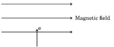
(b) Consider three diagrams in which the entry of a positive charge (+Q) in a magnetic field is shown. Identify the case in which the force experienced by the charge is (i) maximum, and (ii) minimum. (3 Marks)
View Answer Ans:
(a) Rule: Fleming’s left-hand rule.
(b) (i) Maximum force: When velocity is perpendicular to the magnetic field.
(ii) Minimum force: When velocity is parallel to the magnetic field.
(a) Rule:
- Name: Fleming’s left-hand rule.
- Statement: Stretch the thumb, forefinger, and middle finger of the left hand mutually perpendicular. If the forefinger points in the direction of the magnetic field (B) and the middle finger in the direction of the current (I), the thumb points in the direction of the force (F).
(b) Force on a positive charge:
- The force on a moving charge is given by F = qvB sinθ, where q is the charge, v is velocity, B is the magnetic field strength, and θ is the angle between v and B.
- (i) Maximum force: F is maximum when sinθ = 1, i.e., θ = 90° (velocity perpendicular to the magnetic field). In the diagram where +Q’s velocity is perpendicular to B, the force is maximum.
- (ii) Minimum force: F is minimum (zero) when sinθ = 0, i.e., θ = 0° or 180° (velocity parallel or antiparallel to the magnetic field). In the diagram where +Q’s velocity is parallel to B, the force is zero.
Conclusion: Maximum force at θ = 90°, minimum at θ = 0° or 180°.
Q7: What are magnetic field lines? List two important properties of magnetic field lines. (2 Marks)
View Answer Ans:
Magnetic field lines: These are visual representations of the magnetic field, showing the direction a north pole would move and indicating field strength by their closeness.
Properties:
- Closed loops: Field lines emerge from the north pole, travel outside to the south pole, and continue inside from south to north, forming continuous loops.
- Non-intersecting: No two field lines cross, as the magnetic field has a unique direction at each point. Intersection would imply multiple directions, which is impossible.
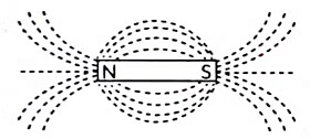
Q8: In order to obtain magnetic field lines around a bar magnet, a student performed an experiment using a magnetic compass and a bar magnet. The magnet was placed on a sheet of white paper fixed on a drawing board. Using a magnetic needle, he obtained on the paper a pattern of magnetic field lines around the bar magnet.
 (a) By convention, the field lines emerge from the north pole and merge at the south pole. Why? Give reason.
(b) State the relationship between the strength of the magnetic field and the degree of closeness of the field lines.
(c) (A) (i) No two field lines can ever intersect each other. Give reason.
(ii) The magnetic field in a given region is uniform. Draw a diagram to represent it. (4 Marks)
View Answer Ans:
(a) Why field lines emerge from north and merge at south:
- By convention, magnetic field lines show the direction a free north pole would move. The north pole of a compass is attracted to the south pole of a magnet and repelled by its north pole. Thus, field lines are drawn emerging from the north pole and merging at the south pole, forming closed loops (inside the magnet, they go from south to north).
(b) Relationship:
- The strength of the magnetic field is proportional to the density of field lines. Where field lines are closer together (e.g., near the poles), the field is stronger; where they are farther apart, the field is weaker.
(c) (A):
- (i) No intersection: Magnetic field lines do not intersect because the magnetic field at any point has a unique direction. If lines crossed, it would imply two different directions at the intersection point, which is physically impossible, as a compass needle can only point in one direction.
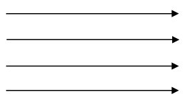
- (ii) Uniform magnetic field:
- Diagram: Draw parallel, equally spaced straight lines with arrows in the same direction (e.g., left to right). This represents a uniform magnetic field, as seen inside a solenoid or between flat magnet poles.
Conclusion: As described above.
OR
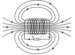
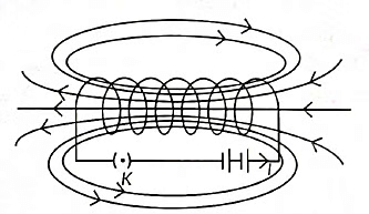
(c) (B) Draw the pattern of the magnetic field lines through and around a current carrying solenoid. What does the pattern of field lines inside the solenoid represent ?
View Answer Ans: 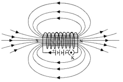
The magnetic field pattern of a current-carrying solenoid resembles that of a bar magnet. One end of the current-carrying solenoid behaves as a magnetic north , while the other behaves as the magnetic south just like in the bar magnet.
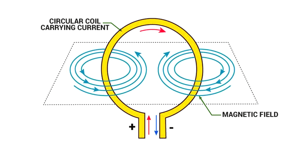
Q9: (a) What are magnetic field lines? How is the direction of the magnetic field at a point determined? Draw the pattern of magnetic field lines of the magnetic field produced by a current-carrying circular loop. Mark on it the direction of (i) current and (ii) magnetic field lines. Name the two factors on which the magnitude of the magnetic field due to a current-carrying coil depends.
View Answer Ans:
Magnetic field lines: These are imaginary lines that indicate the direction a north pole would move and show field strength by their density.
Direction determination: Place a small compass needle at the point; the needle’s north pole points in the direction of the magnetic field at that point.
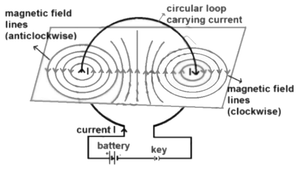
Factors affecting field magnitude: B = (μ₀NI)/(2r).
- Current (I): Higher current increases the field strength.
- Number of turns (N): More turns increase the field strength.
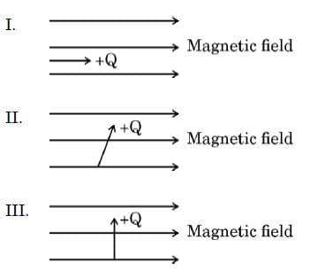
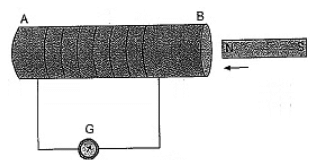
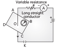
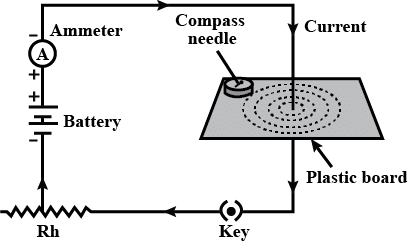
Q10: (a) Study the following electric circuit diagram and answer the questions that follow :
(i) What does the circuit diagram show?
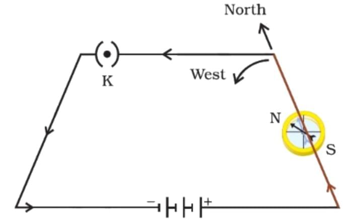
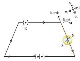 (ii) What will happen if the direction of current is reversed? Justify your answer giving a circuit diagram.
(b) Name and state the rule to determine the direction of magnetic field associated with a straight current carrying conductor. (5 Marks)
View Answer Ans:
(a) (i) The circuit diagram shows a current-carrying conductor placed near a compass needle. The conductor appears to form a trapezoidal loop with a key (K) to control the current flow. The compass needle, positioned near the conductor, is used to detect the magnetic field generated by the current. This setup is typically used to demonstrate the relationship between electric current and the magnetic field it produces, such as in an experiment to verify the magnetic effect of current.
(a) (ii) Reversing current:
- Effect: Reversing the current direction reverses the force direction on the conductor, per Fleming’s left-hand rule. For example, if the original force is upward, it becomes downward.
- Justification: The force direction depends on the current direction (middle finger in Fleming’s rule). Reversing the current (e.g., by swapping battery terminals) changes the middle finger’s direction, reversing the thumb (force).
(b) Rule:
- Name: Right-hand thumb rule.
- Statement: Hold the conductor with the right hand, thumb pointing in the current direction. The curled fingers indicate the magnetic field direction (concentric circles around the conductor).
OR
(a) Draw the pattern of magnetic field lines of
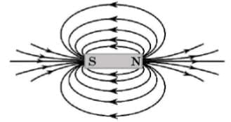
(i) a bar magnet
(ii) a current carrying solenoid.
List two distinguishing features between the two magnetic fields.
(b) Study the following three diagrams in which the entry of an electron in a magnetic field is shown. Identify the case in which the magnetic force experienced by the electron is (i) maximum, and (ii) minimum. Give reason for your answers in each case. (5 Marks)
View Answer Ans: (a)
(i) 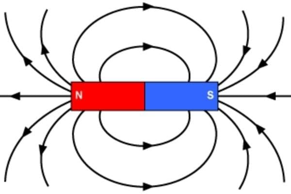
(ii) 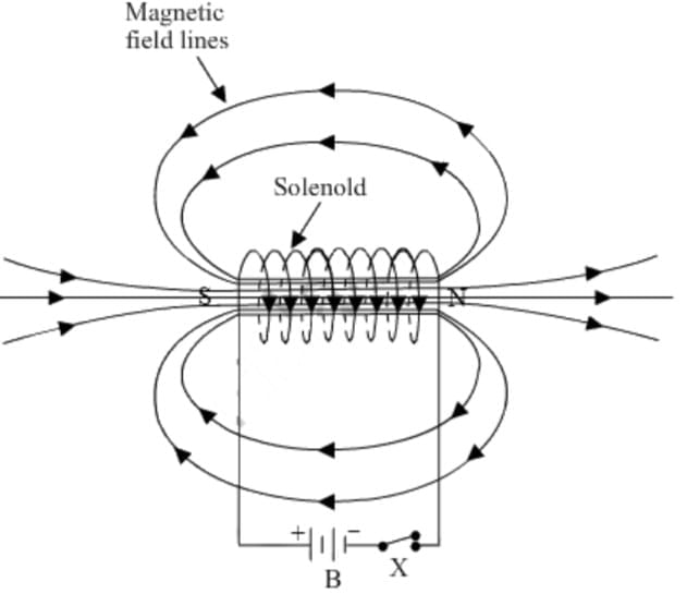
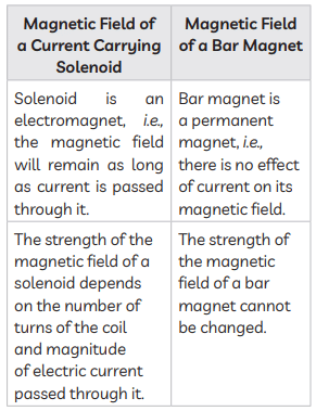
Two distinguishing features between the two fields:
The magnetic field of the solenoid can be varied as per our requirements just by changing the current or core of the solenoid whereas the magnetic field of the bar magnet is fixed.
The magnetic field outside the solenoid is negligible as compared to the bar magnet.
(b) Let's analyze each case using the magnetic force on a moving charge:
F=q v B sin θ
Where:
q = charge of particle (electron has negative charge)
v = velocity of electron
B = magnetic field strength
θ = angle between velocity of electron and magnetic field
Case (A): Electron velocity is perpendicular to magnetic field (θ = 90∘)
sin90∘=1
Force is maximum.
Case (B): Electron velocity is at an angle (oblique) to magnetic field (0° < θ < 90°).
sinθ is less than 1 but not zero.
Force is less than maximum but not zero.
Case (C): Electron velocity is parallel (or anti-parallel) to magnetic field (θ = 0∘ or 180∘)
Sin 0∘= 0 or sin 180∘= 0.
Force is minimum (zero).
Q11: Answer the following questions for a case in which a current carrying conductor is placed in a uniform magnetic field :
(a) List three factors on which the magnitude of the force acting on a current-carrying conductor in a uniform magnetic field depends.
(b) When is the magnitude of the force on the conductor maximum?
(c) Name the rule which helps in determining the direction of force on the conductor and give its one application. (3 Marks)
View Answer Ans:
(a) Factors: The force on a current-carrying conductor is given by F = BIL sinθ.
- Current (I): Higher current increases the force.
- Magnetic field strength (B): Stronger field increases the force.
- Length (L): Longer conductor in the field increases the force.
[Note: The angle θ also affects the force, but the question asks for three factors.]
(b) Maximum force: F = BIL sinθ is maximum when sinθ = 1, i.e., θ = 90° (conductor perpendicular to the magnetic field).
(c) Rule and application:
- Name: Fleming’s left-hand rule.
- Statement: Stretch the thumb, forefinger, and middle finger of the left hand mutually perpendicular. Forefinger points to the magnetic field (B), middle finger to the current (I), and thumb to the force (F).
- Application: In an electric motor, the rule determines the direction of force on the current-carrying coil, causing it to rotate in the magnetic field, converting electrical energy to mechanical energy.
Q12: Why can’t two magnetic field lines cross each other? Draw magnetic field lines showing the direction of the magnetic field due to a current-carrying long straight solenoid. State the conclusion which can be drawn from the pattern of magnetic field lines inside the solenoid. Name any two factors on which the magnitude of the magnetic field due to this solenoid depends. (5 Marks)
View Answer Ans:
If two magnetic field lines will cross each other, then there will be two directions of magnetic field at the point of crossing, which is not possible in a magnetic field. The field around a solenoid is like that of a bar magnet.
Diagram:
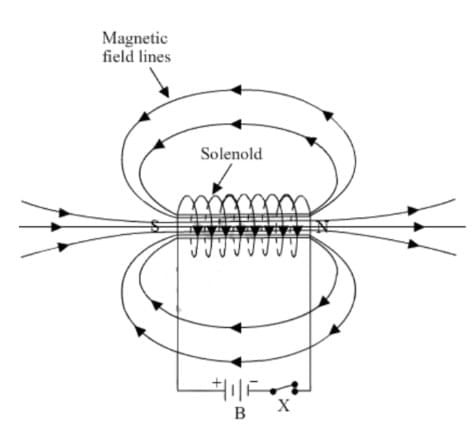
Conclusion: The field lines inside the solenoid are straight, parallel, and equally spaced, indicating a uniform magnetic field, similar to a bar magnet’s interior field.
Factors: The magnetic field inside a solenoid is B = μ₀nI.
- Current (I): Higher current increases the field strength.
- Number of turns per unit length (n): More turns per unit length increase the field strength.
Previous Year Questions 2024
Q1: (i) Two magnetic field lines do not intersect each other. Why?
(ii) How is a uniform magnetic field in a given region represented? Draw a diagram in support of your answer. (1 to 3 Marks) (2024)
Q2: Strength of magnetic field produced by a current carrying solenoid DOES NOT depend upon: (1 Mark) (2024)
(a) number of turns in the solenoid
(b) direction of the current flowing through it
(c) radius of solenoid
(d) material of core of the solenoid
View Answer Ans: (b)
The strength of the magnetic field in a solenoid depends on factors like the number of turns of wire and the radius of the solenoid. However, the direction of the current (whether it flows one way or the opposite) does not affect the strength of the magnetic field itself; it only changes the direction of the field. Therefore, the correct answer is (b).
Q3: Assertion - Reason based questions: (1 Mark) (2024)
These questions consist of two statements — Assertion (A) and Reason (R). Answer these questions selecting the appropriate option given below:
(a) Both (A) and (R) are true and (R) is the correct explanation of (A).
(b) Both (A) and (R) are true, but (R) is not the correct explanation of (A).
(c) (A) is true, but (R) is false.
(d) (A) is false, but (R) is true.
Assertion (A): The deflection of a compass needle placed near a current carrying wire decreases when the magnitude of an electric current in the wire is increased.
Reason (R): Strength of the magnetic field at a point due to a current carrying conductor increases on increasing the current in the conductor.
View Answer Ans: (d)
The assertion states that the deflection of a compass needle decreases as the current increases, which is false. The reason explains that the magnetic field strength increases with more current, which is true. Therefore, the correct answer is (d), as the assertion is false while the reason is true.
Q4: Draw a diagram to show the pattern of magnetic field lines on a horizontal sheet of paper due to a straight conductor passing through its centre and carrying current vertically upwards. Mark on it (i) the direction of current in the conductor and (ii) the corresponding magnetic field lines. State right hand thumb rule and check whether the directions marked by you are in accordance with this rule or not. (1 to 3 Marks) CBSE 2024)
View Answer Ans: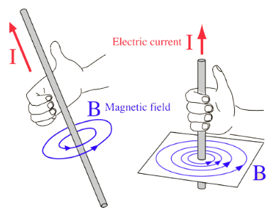
Right-Hand Thumb Rule: When a current-carrying straight conductor is being held in right-hand such that the thumb points towards the direction of current, then fingers will wrap around the conductor in the direction of the magnetic field lines.
Q5: Name the device used to magnetise a piece of magnetic material. Draw a labelled diagram to show the arrangement used for the magnetisation of a cylinder made of soft iron. (1 to 3 Marks) (CBSE 2024)
Q6: A rectangular loop ABCD carrying a current I is situated near a straight conductor XY, such that the conductor is parallel to the side AB of the loop and is in the plane of the loop. If a steady current I is established in the conductor as shown, the conductor XY will (1 Mark) (2024)
 (a) remain stationary.
(b) move towards the side AB of the loop.
(c) move away from the side AB of the loop.
(d) rotate about its axis.
View Answer Ans: (b)
A rectangular loop ABCD carrying a current I is situated near a straight conductor XY, such that the conductor is parallel to the side AB of the loop and is in the plane of the loop. If a steady current I is established in the conductor as shown, the conductor XY will move towards the side AB of the loop.
Q7: Two statements are given one labelled as Assertion (A) and the other labelled as Reason (R). Select the correct answer to these questions from the codes (A), (B), (C) and (D) as given below. (1 Mark) (2024)
(a) Both Assertion (A) and Reason (R) are true and Reason (R) is the correct explanation of Assertion (A).
(b) Both Assertion (A) and Reason (R) are true, but Reason (R) is not the correct explanation of Assertion (A).
(c) Assertion (A) is true, but Reason (R) is false.
(d) Assertion (A) is false, but Reason (R) is true.
Assertion (A): Magnetic field lines never intersect each other.
Reason (R): If they intersect, then at the point of intersection, the compass needle would point towards two directions, which is not possible.
View Answer Ans: (a)
The assertion states that magnetic field lines never intersect, which is true. The reason explains that if they did intersect, a compass needle would point in two different directions at that point, which is also true. Since the reason correctly explains why the assertion is true, the correct answer is (a).
Q8: A student fixes a sheet of white paper on a drawing board. He places a bar magnet in the centre of it. He sprinkles some iron filings uniformly around the bar magnet. Then he taps the drawing board gently and observes that the iron filings arrange themselves in a particular pattern. (4 to 5 Marks) (2024)
(a) Why do iron filings arrange in a particular pattern?
(b) What does the crowding of iron filings at the ends of the magnet indicate?
(c) What do the lines, along which the iron filings align, represent?
(d) If the student places a cardboard horizontally in a current carrying solenoid and repeats the above activity, in what pattern would the iron filings arrange? State the conclusion drawn about the magnetic field based on the observed pattern of the lines.
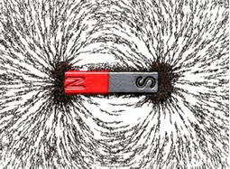
View Answer Ans: (a) The iron filings arrange themselves in a particular pattern because they align with the magnetic field lines created by the bar magnet. The filings act like tiny magnets and are attracted to the lines of force, forming a pattern that shows the shape of the magnetic field around the magnet.
(b) The crowding of iron filings at the ends of the magnet indicates the location of the magnetic poles. The magnetic field is stronger at the poles of the magnet, which is why the filings are more concentrated in these regions. This shows the magnetic field lines emerging from the north pole and entering the south pole.
(c)The lines along which the iron filings align represent the magnetic field lines. These are the paths along which the magnetic force is exerted. The pattern formed by the iron filings shows the direction and shape of the magnetic field around the magnet.
(d) If the student places a cardboard horizontally in a current-carrying solenoid and repeats the activity, the iron filings would arrange themselves in concentric circles around the solenoid, with the pattern showing loops around the solenoid. The magnetic field of a solenoid is similar to that of a bar magnet, with distinct field lines forming a pattern resembling that of a bar magnet's poles.
Conclusion: The magnetic field inside a solenoid is uniform and parallel to its axis, while outside the solenoid, the magnetic field resembles that of a bar magnet, with a clear direction from one end (north) to the other (south)
Q9: The current-carrying device which produces a magnetic field similar to that of a bar magnet is: (1 Mark) (2024)
(a) A straight conductor
(b) A circular loop
(c) A solenoid
(d) A circular coil
View Answer Ans: (c)
A solenoid is a coil of wire that, when carrying an electric current, creates a magnetic field similar to that of a bar magnet, with distinct north and south poles. This means that a solenoid can generate a uniform magnetic field inside it, making it behave like a bar magnet. Therefore, the correct answer is (c).
Q10:

A uniform magnetic field exists in the plane of the paper as shown in the diagram. In this field, an electron (e-) and a positron (p+) enter as shown. The electron and positron experience forces: (1 Mark) (2024)
(a) both pointing into the plane of the paper.
(b) both pointing out of the plane of the paper.
(c) pointing into the plane of the paper and out of the plane of the paper respectively.
(d) pointing out of the plane of the paper and into the plane of the paper respectively.
View Answer Ans: (d)
pointing out of the plane of the paper and into the plane of the paper respectively.
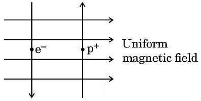
The forces on the electron and positron will be in opposite directions according to the right-hand rule, as they have opposite charges. This means the force on the electron will be in one direction and the force on the positron will be in the opposite direction.
Q11: (a) What happens when a bundle of wires of soft iron is placed inside the coil of a solenoid carrying a steady current? Name the device obtained. Why is it called so?
(b) Draw the magnetic field lines inside a current carrying solenoid. What does this pattern of magnetic field lines indicate? (1 to 3 Marks) (2024)
View Answer Ans: (a)
- When a bundle of wires made of soft iron is placed inside the coil of a solenoid carrying a steady current, the following occurs:
- The soft iron wires become magnetised.
- This happens because the magnetic field generated by the current in the solenoid induces magnetism in the iron.
- The device formed as a result of this process is called an electromagnet.
- It is termed an electromagnet because it behaves like a magnet only when there is an electric current flowing through the solenoid.
(b)
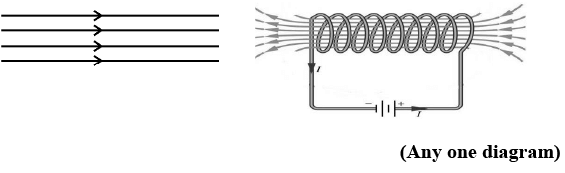
This pattern indicates that the magnetic field is uniform and Parallel.
Q12: The pattern of the magnetic field produced inside solenoid is: (1 Mark) (2024)
(a) 
(b) 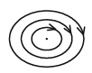
(c)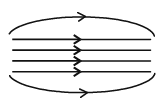
(c) 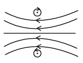
View Answer Ans: (a)
The pattern of the magnetic field inside a solenoid is uniform and parallel, resembling straight lines. This means that the magnetic field strength is consistent throughout the solenoid, making it effective for applications requiring a stable magnetic field. Therefore, the correct answer is (a).
Previous Year Questions 2023
Q1: Assertion (A) : The magnetic field lines around a current carrying straight wire do not intersect each other.
Reason (R) : The magnitude of the magnetic field produced at a given point increases as the current through the wire increases. (1 Mark) (2023)
(a) Both Assertion (A) and Reason (R) are true and Reason (R) is the correct explanation of the Assertion (A)
(b) Both Assertion (A) and Reason (R) are true, but Reason (R) is not the correct explanation of the Assertion (A)
(c) Assertion (A) is true, but Reason (R) is False.
(d) Assertion (A) is false, but Reason (R) is true.
Ans: (b)
View Answer Sol: Assertion is true and reason is also true, but reason is not the correct explanation of assertion. Magnetic field lines around a current carrying straight wire do not intersect each other because at the point of intersection there will be two directions which is not possible. Also, the strength of magnetic held increased by increasing the magnitude of the current in the wire.
Q2: Draw the pattern of the magnetic field produced around a vertical current carrying straight conductor passing through a horizontal cardboard. Mark the direction of current and the magnetic field lines. Name and state the rule which is used to determine the direction of magnetic field associated with a current carrying conductor. (3 Marks) (2023)
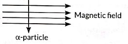
Q3: An alpha particle enters a uniform magnetic field as shown. The direction of force experienced by the alpha particle is ____ (1 Mark) (2023)
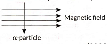
(a) Towards right
(b) towards left
(c) Into the page
(d) Out of the page
Ans: (d)
View Answer Sol: According to the Fleming’s left hand rule, the direction of force is out of the page.
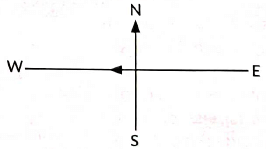
Q4: A constant current flows in a horizontal wire in the plane of the paper from east to west as shown in the figure. The direction of the magnetic field will be north to south at a point N (1 Mark) (2023)
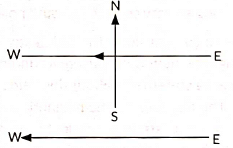
(a) Directly above the wire
(b) Directly below the wire
(c) Located in the plane of the paper on the north side of the wire
(d) Located in the plane of the paper on the south side of the wire
View Answer Ans: (a)
The direction of the magnetic field at point N, located above a horizontal wire carrying a constant current from east to west, is from north to south. This can be determined using the right-hand thumb rule, which states that if you hold the wire with your right hand and point your thumb in the direction of the current, your fingers will curl in the direction of the magnetic field lines.
Q5: Assertion : A current carrying straight conductor experiences a force when placed perpendicular to the direction of magnetic field.
Reason : The net charge on a current carrying conductor is always zero, (1 Mark) (2023)
(a) Both A and R are true and R is the correct explanation of A.
(b) Both A and R are true and R is not the correct explanation of A.
(c) A is true but R is false.
(d) A is false but R is true.
View Answer Ans: (b)
Sol:
Assertion (A) is true because a current-carrying conductor placed perpendicular to a magnetic field experiences a force (Fleming’s Left-Hand Rule).
Reason (R) is true because a current-carrying conductor remains electrically neutral (equal protons and electrons).
However, R does not explain A. The force arises due to the motion of charges (current), not the net charge being zero. Thus, (b) is correct.
Q6: (i) Why is an alternating current (A.C.) considered to be advantageous over direct current (D.C.) for the long distance transmission of electric power?
(ii) How is the type of current used in household supply different from the one given by a battery of dry cells?
(iii) How does an electric fuse prevent the electric circuit and the appliances from the possible damage due to short circuiting or overloading. (3 Marks) (2023)
View Answer Ans: (i) Alternating current (A.C.) is preferred for long-distance power transmission because it experiences significantly lower power loss compared to direct current (D.C.). This efficiency makes A.C. more suitable for delivering electricity over vast distances.
(ii) The current used in household supply is alternating in nature while the current given by battery is direct in nature.
(iii) Electric fuse protects circuits and appliances by stopping the flow of any unduly high electric current. It consists of a piece of wire made of a metal or an alloy of appropriate melting point, for example aluminium, copper, iron, lead etc. If a current larger than the specified value flows through the circuit, the temperature of the fuse wire increases. This melts the fuse wire and breaks the circuit.
Q7: (A) State the rule used to find the force acting on a current carrying conductor placed in a magnetic field.
(B) Given below are three diagrams showing entry of an electron in a magnetic field. Identify the case in which the force will be (1) maximum and (2) minimum respectively. Give reason for your answer. (1 to 3 Marks) (CBSE 2023)
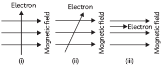
View Answer Ans: (A) Fleming’s left-hand rule is used to determine the direction of force experienced by a current carrying conductor placed in a uniform magnetic field. Acc to Fleming’s Left Hand Rule: When a current carrying conductor is placed in a magnetic field, it experiences a force, whose direction is given by Fleming’s left hand rule, which states that “Stretch the forefinger, the central finger and the thumb of your left hand mutually perpendicular to each other. If the forefinger shows the direction of the field and the central finger that of the current, then the thumb will point towards the direction of motion of the conductor, i.e., force.”
(B) Force on electron is maximum in (i) case because the electron direction show that it is moving at right angle to the direction of a magnetic field. Force on electron is minimum in (iii) case as the electron shown is moving parallel to the direction of a magnetic field. The direction of maximum force acting on an electron in (i) case which is into the plane of paper in accordance with Fleming’s left hand rule.
Q8: (A) Draw the pattern of magnetic field lines of:
(i) a current carrying solenoid
(ii) a bar magnet
(B) List two distinguishing features between the two fields. (1 to 3 Marks) (CBSE 2023)
Previous Year Questions 2022
Q1: Give reason for the following (i) There is either a convergence or a divergence of magnetic field lines near the ends of a current carrying straight solenoid. (ii) The current carrying solenoid when suspended freely rests along a particular direction. (2022)View Answer Ans: (i) There is either a convergence or a divergence of magnetic field lines near the ends of a current carrying straight solenoid because it behaves similar to that of a bar magnet and has a magnetic field line pattern similar to that of a bar magnet. Thus the ends of the straight solenoid behaves like poles of the magnet, where the converging end is the south pole and the diverging end is the north pole.
(ii) The current carrying solenoid behaves similar to that of a bar magnet and when freely suspended aligns itself in the north-south direction.
Q2: A student fixes a sheet of white paper on a drawing board using some adhesive materials. She places a bar magnet in the centre of it and sprinkles some iron filings uniformly around the bar magnet using a salt-sprinkler. On tapping the board gently, she observes that the iron filings have arranged themselves in a particular pattern.
(a) Draw a diagram to show this pattern of iron filings.
(b) What does this pattern of iron filings demonstrate?
(c) (i) How is the direction of magnetic field at a point determined using the field lines? Why do two magnetic field lines not cross each other? (2022)
View Answer Ans: (a) The pattern of iron filings is shown below.
(b) This pattern of iron filings demonstrate that the magnet exerts its influence in the region surrounding it. Therefore, the iron filings experience a force. The lines along which the iron filings align themselves represent magnetic field lines.
(c) (i) The direction of magnetic field is determined by placing a small compass needle in the magnetic field. The North-pole of the compass indicates the direction of magnetic field at that point.
Magnetic field lines never intersect each other because it is not possible to have two directions of magnetic field at the same point.
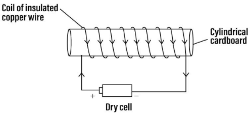
Q3: (i) What is a solenoid?
(ii) Draw the pattern of magnetic field lines of the magnetic field produced by a solenoid through which a steady current flows. (2022)
View Answer Ans: (i) A coil of many circular turns of insulated copper wire wrapped closely in the shape of a cylinder is called a solenoid.
(ii)
Q4: When is the force experienced by a current - carrying straight conductor placed in a uniform magnetic field
(i) Maximum;
(ii) Minimum? (2022)
View Answer Ans: The magnitude of force experienced by a current carrying conductor placed in a uniform magnetic field is
(i) maximum when the conductor is placed perpendicular to the magnetic field,
(ii) minimum when the conductor is placed parallel to the magnetic field.
Q5: (i) Name and state the rule to determine the direction of force experienced by a current carrying straight conductor placed in a uniform magnetic field which is perpendicular to it.
(ii) An alpha particle while passing through a magnetic field gets projected towards north. In which direction will an electron project when it passes through the same magnetic field? (2022)
View Answer Ans: (i) Fleming's left-hand rule is used to determine the direction of magnetic force experienced by a current carrying straight conductor placed perpendicularly in a uniform magnetic field.
Fleming's left-hand rule, states that when left hand’s thumb, forefinger and centre finger are held mutually perpendicular to one another and adjusted in such a way that the forefinger points in the direction of magnetic field, and the centre finger points in the direction of the current, then the direction in which thumb points, gives the direction of force acting on the conductor.
(ii) As we know that, an alpha particle is positively charged. It is given that an alpha particle while passing through a magnetic field gets deflected (projected) towards north. Since an electron is negatively charged, it will deflect in Opposite direction i.e.. south.
Q6: A student was asked to perform an experiment to study the force on a current carrying conductor in a magnetic field. He took a small aluminium rod AB, a strong horseshoe magnet, some connecting wires, a battery and a switch and connected them as shown. He observed that on passing current, the rod gets displaced. On reversing the direction of current, the direction of displacement also gets reversed. On the basis of your understanding of this phenomenon, answer the following questions:
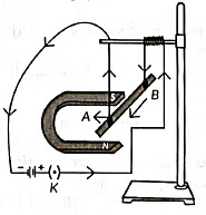
(a) Why does the rod get displaced on passing current through it?
(b) State the rule that determines the direction of the force on the conductor AB.
(c) If the U shaped magnet is held vertically and the aluminium rod is suspended horizontally with its end B towards due north, then on passing current through the rod B to A as shown, in which direction will the rod be displaced? (2022)
View Answer Ans: (a) On passing current, the rod gets displaced because of a magnetic force exerted on the rod when it is placed in the magnetic field.
(b) Fleming’s left hand rule is used to determine the direction of magnetic force exerted on the conductor AB.
(c) The rod will be displaced towards left according to Fleming’s left-hand rule.
Previous Year Questions 2021
Q1: Why do two magnetic field lines not intersect each other? (2021C)
Q2: Name the instrument used to detect the presence of a current in a circuit. (2021C)
View Answer Ans: Galvanometer is used to detect the current in a circuit.
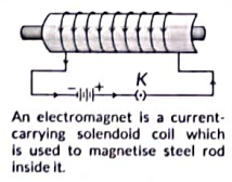
Q3: What is an electromagnet? (2021C)
View Answer Ans: An electromagnet is a current-carrying solenoid coil which is used to magnetise steel rod inside it.
Q4: (a) Name the poles P, Q, R and S of the magnets in the following figures 'a' and 'b':
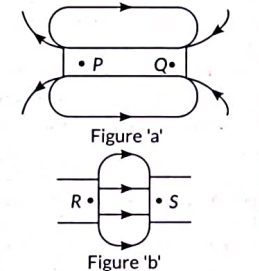
(b) State the inference drawn about the direction of the magnetic field lines on the basis of these diagrams. (Term II, 2021-22)
View Answer Ans: (a) In Figure 'a', poles P and Q of the magnet represents north pole and south pole respectively. In figure 'b', poles R and S of the magnet also represents north pole and south pole respectively.
(b) Magnetic field lines are closed continuous curves directed from north pole to south pole outside the magnet but from south pole to north pole inside the magnet.
Q5: List two factors on which the strength of magnetic field at a point due to a current carrying straight conductor depends. State the rule that determines the direction of magnetic field produced in this case. (Term II, 2021-22C)
Previous Year Questions 2020
Q1: (a) What is an electromagnet? List any two uses.
(b) Draw a labelled diagram to show how an electromagnet is made.
(c) State the purpose of soft iron core used in making an electromagnet.
(d) List two ways of increasing the strength of an electromagnet if the material of the electromagnet is fixed. (2020)
Q2: Give reasons for the following:
(A) There is either a convergence or a divergence of magnetic field lines near the ends of a current carrying straight solenoid.
(B) The current carrying solenoid when suspended freely rests along a particular direction. (CBSE 2020)
View Answer Ans: (A) There is a divergence of magnetic field lines near the ends of a current carrying straight solenoid as the ends of the solenoid behave as poles. So, lines emerge and enter the ends, crowding the space and appearing divergent.
(B) The current carrying solenoid when suspended freely rests along a particular direction because a current carrying solenoid behaves like a bar magnet with fixed polarities at its ends. The magnetic field lines are exactly identical to those of a bar magnet with one end of solenoid acting as a south-pole and its other end as north-pole
Q3: (A)Draw the pattern of magnetic field lines due to a magnetic field through and around a current carrying circular loop.
(B) Name and state the rule to find out the direction of magnetic field inside and around the loop. (CBSE 2020)
View Answer Ans: (A)
(B) The rule used to find the direction of magnetic field lines is right hand thumb rule, which states that if we had the loop wire in our hand such that our thumb points in direction of current then our curled finger show the direction of field at that point.
Q4: What is the role of a fuse used in series with any electrical appliance? Why should a fuse with a defined rating not be replaced by one with a larger rating? (CBSE 2020, 19, 17, 10)
View Answer Ans:
- A fuse in a circuit prevents damage to the appliances and the circuit due to overloading and short-circuiting.
- Overloading can occur when the live wire and the neutral wire come into direct contact.
- In such a situation, the current in the circuit abruptly increases. This is called short-circuiting.
- The use of an electric fuse prevents the electric circuit and the appliance from a possible damage by stopping the flow of unduly high electric current.
- According to Joule's Law of heating that takes place in the fuse, it melts to break the electric circuit.
- So, a fuse is always connected in series with an appliance.
- If it is connected in parallel, then it will not be able to break the circuit and the current keeps on flowing.
- Overloading can also occur due to an accidental hike in the supply voltage.
- Sometimes, overloading is caused by connecting too many appliances to a single socket.
- The fuse with defined rating means the maximum current that can flow through the fuse without melting it.
- It blows off when a current more than the rated value flows through it.
- If a fuse is replaced by one with larger ratings, then large current will flow through the circuit without melting the fuse.
- This large current may damage the appliances.
Q5: (A) What is an electromagnet? List any two uses.
(B) Draw a labelled diagram to show how an electromagnet is made.
(C) State the purpose of soft iron core used in making an electromagnet.
(D) List two ways of increasing the strength of an electromagnet if the material of the electromagnet is fixed. (CBSE 2020)
View Answer Ans: (A) An electromagnet is a temporary strong magnet. Its magnetism is only for the duration of current passing through it. The polarity and strength of an electromagnet can be changed.
Uses of electromagnet:
Electromagnets are used:
(1) In electrical appliances like electric bell, electric fan etc.
(2) In electric motors and generators.
(B) 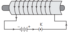
(C) Soft iron core is used in electromagnets to enhance their strength. The soft iron becomes magnetised when current flows through the coil, significantly increasing the overall magnetic field.
(D) Ways of increasing the strength of an electromagnet:
(1) If we increase the number of turns in the coil, the strength of electromagnet increases.
(2) If the current in the coil is increased, the strength of electromagnet increases
Previous Year Questions 2019
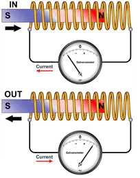
Q1: Two circular coils P and Q are kept close to each other, of which coil P carries a current. What will you observe in the galvanometer connected across the coil Q,
(a) if current in the coil P is changed?
(b) if both the coils are moved in the same direction with the same speed?Give reason to justify your answer in each case. (CBSE 2011, 2019)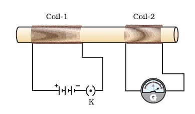
View Answer Ans: (a) When the current in coil P is increased, the galvanometer connected to coil Q shows a momentary deflection in one direction. Conversely, if the current in coil P is decreased, the galvanometer deflects in the opposite direction. This occurs because a change in current alters the magnetic field around coil P, which in turn induces a current in coil Q, resulting in the galvanometer's deflection.
(b) If both the coils P and Q are moved in the same direction with the same speed, the magnetic field of both the coils remain unchanged. Hence no induced current is set up in coil Q and there is no deflection in the galvanometer.
Q2: What is the function of a galvanometer in a circuit? (CBSE 2019)
View Answer Ans: A Galvanometer is an instrument used to detect the presence of current in a circuit. It indicates whether current is flowing and, if so, its direction.
Q3: One of the major causes of fire in office buildings is short-circuiting. List three reasons which may lead to short-circuiting. How can it be prevented? (CBSE 2019)
View Answer Ans: Three possible reasons of short-circuiting of an electrical circuit are as follows:
- The insulation of electrical wirings is damaged.
- The electrical appliance used in the circuit is defective.
- An appliance of higher power rating is being run on an electrical line of lower power rating.
Short-circuiting can be prevented by the use of electrical fuse of appropriate capacity.
Q4: Draw magnetic field lines produced around a current carrying straight conductor passing through a cardboard. Name, state and apply the rule to mark the direction of these field lines. How will the strength of the magnetic field change when the point where magnetic field to be determined is moved away from the straight conductor? Give reason to justify your answer. (Allahabad 2019)
View Answer Ans:
Right-Hand Thumb Rule.
- The Right-Hand Thumb Rule helps determine the direction of the magnetic field around a straight current-carrying conductor.
- To apply this rule, hold the conductor in your right hand with your thumb pointing in the direction of the current.
- Your curled fingers will then indicate the direction of the magnetic field lines surrounding the wire.
- To assess the strength of the magnetic field, a compass needle can be used.
- As the needle is moved further away from the conductor, the deflection decreases.
- This indicates that the strength of the magnetic field diminishes with increasing distance from the wire.
- The magnetic field lines form concentric circles around the conductor, which become larger as one moves away from it.
Previous Year Questions 2018
Q1: (a) What are magnetic field lines? How is the direction of magnetic field at a point in a magnetic field determined using field lines? (b) Two circular coils 'X' and 'Y' are placed close to each other. If the current in the coil 'X' is changed, will some current be induced in the coil 'Y'? Give reason.(c) State 'Fleming's right hand rule. (CBSE 2018C) (5 marks)View Answer Ans: (a) Magnetic field lines are imaginary lines along which the north magnetic pole would move in a magnetic field. The direction of a magnetic field at a point is determined by placing a small compass needle. The North pole of the compass indicates the direction of the magnetic field at that point
(b) Yes, if the current in coil X is changed, the magnetic field associated with it also changes around the coil 'Y' placed close to 'X'. This change in magnetic field lines linked with 'Y', according to Faraday law of electric magnetic induction, induces a current in the coil Y.
(c) Right-Hand Thumb Rule. This rule is used to find the direction of magnetic field due to a straight current carrying wire.
It states that if we hold the current carrying conductor in the right hand in such a way that the thumb is stretched along the direction of current, then the curly finger around the conductor represent the direction of magnetic field produced by it. This is known as right-hand thumb rule.
Direction of Field Lines due to current carrying straight conductor as shown in figure.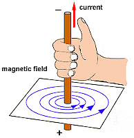
Q2: (a) State Fleming’s left hand rule.
(b) Write the principle of working of an electric motor.
(c) Explain the function of the following parts of an electric motor.
(i) Armature
(ii) Brushes
(iii) Split ring (CBSE 2018)
View Answer Ans: (a) Fleming’s Left-Hand Rule: Stretch the thumb, forefinger and middle finger of the left hand such that they are mutually perpendicular to each other. If the forefinger pointed towards the direction of magnetic field and middle finger in the direction of current, then the thumb will indicate the direction of motion or force experienced by the conductor. It is to be applied only when the current and magnetic field, both are perpendicular to each other.
(b) Principle of an electric motor: It works on the principle of magnetic effect of current. When a current carrying conductor is placed perpendicular to the magnetic field, it experiences a force. The direction of this force is given by Fleming’s left hand rule.
(c) (i) Armature: It consists of a large number of turns of insulated current-carrying copper wires wound over a soft iron core and rotated about an axis perpendicular to a uniform magnetic field supplied by the two poles of permanent magnet.
(ii) Brushes: Two conducting stationary carbon or flexible metallic brushes constantly touches the revolving split rings or commutator. These brushes act as a contact between commutator and terminal battery.
(iii) Split ring: The split ring acts as a commutator in an electric motor. With the help of split ring, the direction of current through the coil is reversed after every half of its rotation and make the direction of currents in both the arms of rotating coil remains same. Therefore, the coil continues to rotate in the same direction.
Previous Year Questions 2017
Q1: The most important safety method used for protecting home appliances from short circuiting or overloading is:
(a) earthing
(b) use of fuse
(c) use of stabilizers
(d) use of electric meter (CBSE 2017, 13)View Answer Ans: (b)
A fuse is a safety device that protects electrical appliances and circuits from damage caused by overloading or short circuits. It contains a metal wire that melts when excessive current flows through it, breaking the circuit and stopping the flow of electricity, which prevents potential damage to appliances and reduces fire risk.
Here’s why the other options are not as suitable for preventing short circuits or overloading:
(a) Earthing: Protects against electric shocks but does not prevent overloading.
(c) Use of stabilizers: Helps maintain a stable voltage but doesn’t protect against overloading or short circuits.
(d) Use of electric meter: Measures electricity usage but doesn’t offer any protective function.
Therefore, the most important safety method is the use of a fuse.
Previous Year Questions 2016
Q1: Under what condition is the force by a current-carrying conductor placed in a magnetic field maximum? (2016)View Answer Ans: The force acting on a current-carrying conductor placed in a magnetic field is maximum when the direction of current is at right angles to the direction of the magnetic field.
Q2: What is an electric fuse ? Briefly describe its function.
Or
Explain the use of electrical fuse. What type of fuse material is used for fuse wire and why? (2016)
View Answer Ans: An electric fuse is a device that is used ahead of and in series of an electric circuit as a safety device to prevent the damage caused by short-circuiting or overloading of the circuit.
It is a small, thin wire of a material whose melting point is low. Generally, wire of tin or tin-lead alloy or tin-copper alloy is used as a fuse wire. If due to some fault electric circuit gets short-circuited, then a strong current begins to flow. Due to such a strong flow of current, the fuse wire is heated up and gets melted. As a result, the electric circuit is broken and current flow stops. Thus, possible damage to the circuit and appliances is avoided.
Q3: (a) List four factors on which the magnitude of magnetic force acting on a moving charge in a magnetic field depends.
(b) How will a fine beam of electrons streaming in west to east direction be affected by a magnetic field directed vertically upwards? Explain with the help of a diagram mentioning the rule applied. (2016)
View Answer Ans: (a) The magnitude of the magnetic force acting on a moving charge in a magnetic field depends on:
- The magnitude of charge
- Speed of moving charge
- Strength of magnetic field
- The angle between the direction of motion of charge and the direction of magnetic field.
(b) The electron streaming from west to east is equivalent to a current from east to west. The magnetic field B is vertically upwards and shown by cross marks (x). Hence, in accordance with Fleming’s left-hand rule, the electron will experience a force in north direction and deflected in that direction.
Q4: What is a solenoid? Draw magnetic field lines due to a current-carrying solenoid. Write three important features of the magnetic field obtained. (2016)
Q5: Describe an activity with a neat diagram to demonstrate the presence of magnetic field around a current-carrying straight conductor. (2016)
Q6: (a) Describe an activity todraw a magnetic field line outside a bar magnet from one pole to another pole. (2016)
(b) What does the degree of closeness of field lines represent?
Q7: What type of current is given by a cell? (CBSE 2016)
Q8: Write any one method to induce current in a coil. (CBSE 2016)
View Answer Ans: Whenever magnetic field around a coil is changed, a current is induced in the coil.
Q9: Define magnetic field of a bar magnet. (CBSE 2016)
View Answer Ans: The magnetic field of a bar magnet is the region around the magnet in which force due to magnet can be felt.
Previous Year Questions 2015
Q1: What is the shape of magnetic field lines due to a straight current-carrying conductor? (CBSE 2015) View Answer Ans: The magnetic field lines around a straight current-carrying conductor form concentric circles with the conductor at the centre. As you move away from the conductor, these circles expand. This pattern indicates that the strength of the magnetic field decreases with distance from the wire.
Q2: What are magnetic field lines? (CBSE 2015)
View Answer Ans: A magnetic field line around a magnet is the path along which north pole of a magnetic compass needle points. A magnetic field line gives the direction of magnetic field at a point.
Q3: (a) Describe an activity to show that an electric current-carrying wire behaves like a magnet.
(b) Write the rule which determines the direction of magnetic field held developed around a current-carrying straight conductor. (CBSE 2015)
Q4: Out of the three wires live, neutral or earth, which one goes through ON/ OFF switch? (CBSE 2015)
View Answer Ans: The live wire is the one that goes through the ON/OFF switch. This wire carries the current to the appliance, allowing it to function when the switch is turned on. When the switch is off, the live wire is disconnected from the appliance, stopping the flow of electricity.
Q5: Why does a current-carrying conductor experience a force when it is placed in a magnetic field? (CBSE 2015)
View Answer Ans: A current-carrying conductor produces a magnetic field around it. This magnetic field interacts with the externally applied magnetic field and as a result the conductor experiences a force.
Q6: What is the frequency of A.C. being supplied in our houses? (CBSE 2015)
View Answer Ans: The frequency at which A.C. is supplied to residential houses is 50 Hz.
Q7: Describe an activity to explain how a moving magnet can be used to generate electric current in a coil. (CBSE 2015)
Or
A coil made of insulated copper wire is connected to a galvanometer. What will happen to the deflection of the galvanometer if a bar magnet is pushed into the coil and then pulled out of it? Give reason for your answer and name the phenomenon involved.
Q8: A metallic conductor is suspended perpendicular to the magnetic field of a horse-shoe magnet. The conductor gets displaced towards left when a current is passed through it. What will happen to the displacement of the conductor if the :
(i) current through it is increased?
(ii) horse-shoe magnet is replaced by another stronger horse-shoe magnet?
(iii) direction of current through it is reversed ? (CBSE 2015)
View Answer Ans: (i) On increasing the current flowing through metallic conductor, the force experienced by it is proportionately increased because F ∝ I.
(ii) On using a stronger horse-shoe magnet the magnetic force increases because F ∝ Magnetic Field.
(iii) On reversing the direction of current the direction of force is reversed and conductor is displaced towards right instead of left direction.
Q9: For the current carrying solenoid as shown below, draw magnetic field lines and giving reason explain that out of the three points A, B and C at which point the field strength is maximum and at which point it is minimum. (CBSE 2015)
Q10: What is meant by solenoid? How does a current carrying solenoid behave? Give its main use. (CBSE 2015)
Q11: What are magnetic field lines? Justify the following statements
(a) Two magnetic field lines never intersect each other.
(b) Magnetic field lines are closed curves. (CBSE 2015)
View Answer Ans: Magnetic field lines: It is defined as the path along which the unit North pole (imaginary) tends to move in a magnetic field if free to do so.
(a) The magnetic lines of force do not intersect (or cross) one another. If they do so then at the point of intersection, two drawn tangents at that point indicate that there will be two different directions of the same magnetic field, i.e. the compass needle points in two different directions which is not possible.
(b) Magnetic field lines are closed continuous curves. They emerge out from the north pole of a bar magnet and go into its south pole. Inside the magnet, they move, from south pole to north pole.
Q12: A current-carrying conductor is placed in a magnetic field. Now answer the following :
(i) List the factors on which the magnitude of force experienced by conductor depends.
(ii) When is the magnitude of this force maximum?
(iii) If initially this force was acting from right to left, how will the direction of force change, if :
(a) direction of magnetic field is reversed?
(b) direction of current is reversed? (CBSE 2015)
View Answer Ans: (i) The magnitude of force experienced by the current-carrying conductor when placed in a magnetic field depends on current flowing, length of the conductor, the strength of magnetic field, orientation of conductor in the magnetic field.
(ii) Magnitude of force is maximum when current-carrying conductor is placed at right angles to the direction of magnetic field.
(iii) (a) Direction of force is reversed that is now the force acts from left to right.
(b) Direction of force is reversed that is now the force acts from left to right.
Q13: In our daily life, we use two types of electric current whose current-time graphs are given in Fig. 13.29.
(i) Name the type of current in two cases.
(ii) Identify any one source for each type of current.
(iii) What is the frequency of current in case
(iv) in our country?
(v) Out of the two which one is used in transmitting electric power over long distances and why? (CBSE 2015).
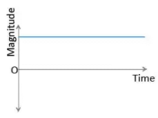 Fig (a)
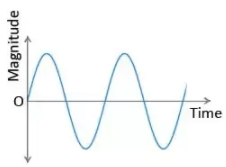 Fig (b)
View Answer Ans: (i) Current shown in Fig. (a) is direct current (D.C.) but current shown in Fig. (b) is an alternating current (A.C.).
(ii) A cell/battery produces D.C. but an A.C. generator produces A.C.
(iii) In India frequency of A.C. is 50 Hz.
(iv) A.C. is used in transmitting electric power over long distances. It is so because transmission loss of electric power can be minimised for A.C. by employing suitable transformers at generating stations and consuming centres.
Q14: A student fixes a sheet of white paper on a drawing board. He places a bar magnet in the centre of it. He sprinkles some iron filings uniformly around the bar magnet. Then he taps the board gently.
Now answer the following questions :
(i) What does the student observe? Draw a diagram to illustrate your answer.
(ii) Why do the iron filings arrange in such a pattern?
(iii) What does the crowding of the iron filings at the ends of the magnet indicate? (CBSE 2015) (5 marks)
Previous Year Questions 2013
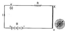
Q1: If the key in the arrangement as shown below is taken out (the circuit is made open) and magnetic field lines are drawn over the horizontal plane ABCD, the lines are:
(a) concentric circles
(b) elliptical in shape
(c) straight lines parallel to each other
(d) concentric circles near the point O but of elliptical shapes as we go away from it. (CBSE 2013)
View Answer Ans: (c)
In the arrangement described, if the key is taken out and the circuit is open, no current flows through the wire. This means that no magnetic field is generated by the wire.
However, if magnetic field lines are drawn over the horizontal plane ABCD in the absence of a current (or any other magnetic source), they would represent the Earth's magnetic field, which appears as straight, parallel lines over a small horizontal area.
Thus, the correct answer is (c) straight lines parallel to each other.
Previous Year Questions 2010
Q1: A magnetic compass needle is placed in the plane of paper near point A, as shown in the figure. In which plane should a straight current carrying conductor be placed so that it passes through A and there is no change in the deflection of the compass? Under what condition is the deflection maximum and why? (CBSE 2010)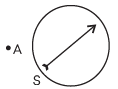
View Answer Ans: The straight current carrying conductor should be placed in the paper plane, passing through A, to produce a magnetic field perpendicular to the paper plane. This ensures the compass needle remains undeflected due to the vertical magnetic field produced by the wire. The maximum deflection in the compass needle occurs when the conductor is perpendicular to the paper plane and the magnetic field is in the paper plane.

 (b) Permanent magnet / Current carrying solenoid/ Electromagnet is used to magnetise a piece of magnetic material.