NCERT Exemplar: System of Particles & Rotational Motion | Physics Class 11 - NEET PDF Download

MULTIPLE CHOICE QUESTIONS I
Q.1. For which of the following does the centre of mass lie outside the body ?
(a) A pencil
(b) A shotput
(c) A dice
(d) A bangle
Ans. (d)
Solution.
A bangle is a ring like shape and the centre of mass of ring lies at its centre which is outside the ring or bangle. Hence verifies the option (d).
Q.2. Which of the following points is the likely position of the centre of mass of the system shown in Figure ?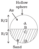 (a) A
(a) A
(b) B
(c) C
(d) D
Ans. (c)
Solution.
The position of centre of mass of the system in this problem is closer to heavier mass or masses or we can say that it depends upon distribution of mass. So it is likely to be at C. In the above diagram, lower part of the sphere containing sand is more heavier than upper part containing air. Hence CM of the system lies below the horizontal diameter.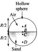
Q.3. A particle of mass m is moving in yz-plane with a uniform velocity v with its trajectory running parallel to +ve y-axis and intersecting z-axis at z = a (Figure). The change in its angular momentum about the origin as it bounces elastically from a wall at y = constant is: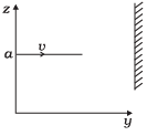 (a) mva êx
(b) 2mva êx
(c) ymv êx
(d) 2ymv êx
Ans. (b)
Solution.
Angular momentum is an axial vector, i.e. always directed perpendicular to the plane of rotation and along the axis of rotation.
In cartesian co-ordinates if 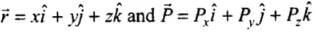
Then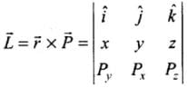

KE of the system remains conserved, in elastic collision. So, the ball will bounce back with the same speed v but in opposite direction, i.e. along -ve y-axis.
The initial velocity is and after reflection from the wall, the final velocity is
  . The trajectory is described as position vector
 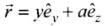 .
.
Hence, the change in angular momentum is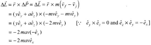
Q.4. When a disc rotates with uniform angular velocity, which of the following is not true?
(a) The sense of rotation remains same.
(b) The orientation of the axis of rotation remains same.
(c ) The speed of rotation is non-zero and remains same.
(d) The angular acceleration is non-zero and remains same.
Ans. (d)
Solution.
The rate of change of angular velocity is defined as angular acceleration. If particle has angular velocity ω1 at time
t1, and angular velocity ω2 at time t2 , then
Angular acceleration α = ω2 – ω1 / t2 – t1
When the disc is rotated with constant angular velocity, angular acceleration of the disc is zero. Because we know that angular acceleration
α = ∆ ω/∆ t
Here ω is constant, so ∆ ω = 0
Q.5. A uniform square plate has a small piece Q of an irregular shape removed and glued to the centre of the plate leaving a hole behind (Figure). The moment of inertia about the z-axis is then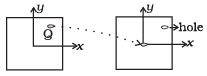 (a) Increased
(b) Decreased
(c) The same
(d) Changed in unpredicted manner
Ans. (b)
Solution.
After removing the matter from Q it is stick at P through axis of rotation passes, but axis of rotation does not passes through Q. So comes closer to the axis of rotation.
Q.6. In previous problem , the CM of the plate is now in the following quadrant of x-y plane,
(a) I
(b) II
(c) III
(d) IV
Ans. (c)
Solution.
Let us consider the diagram below, which shows the position of the piece which is removed from the plate. First center of mass is at the centre of the plate (only if its mass is uniformly distributed over the surface) when the piece is removed from quadrant I, therefore the centre of mass is shifted to the opposite of the quadrant III.
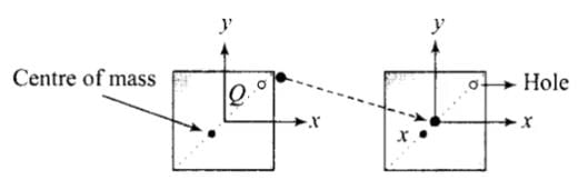
Position of CM is shown by point X in the diagram.
Q.7. The density of a non-uniform rod of length 1m is given by
ρ(x) = a(1+bx2)
where a and b are constants and o≤x≤1.
The centre of mass of the rod will be at
(a)
(b)
(c)
(d)
Ans. (a)
Solution.
ρ(x) = a(1+bx2)
At b 0, p(x) = a i.e./ p is constant in this case C.M. must lies at mid-point of 1 m
i.e., at x = 0.5 m ,by substituting value of b = 0 in option (a), (c), d).
We observe that the C.M. lies at 0.5 m at b = 0.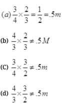 Hence, option (a) verifies.
Q.8. A Merry-go-round, made of a ring-like platform of radius R and mass M, is revolving with angular speed ω . A person of mass M is standing on it. At one instant, the person jumps off the round, radially away from the centre of the round (as seen from the round).
The speed of the round afterwards is
(a) 2ω
(b) ω
(c) ω/2
(d) 0
Ans. (b)
Solution.
As no torque is exerted by the person jumping, radially away from the centre of the round (as seen from the round), let the total moment of inertia of the system is 2I (round + Person (because the total mass is 2M) and the round is revolving with angular speed ω Since the angular momentum of the person when it jumps off the round is Iω the actual momentum of round seen from ground is 2Iω – Iω = Iω
So we conclude that the angular speed remains same, i.e ω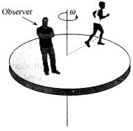
MULTIPLE CHOICE QUESTIONS II
Q.1. Choose the correct alternatives:
(a) For a general rotational motion, angular momentum L and angular velocity ω need not be parallel.
(b) For a rotational motion about a fixed axis, angular momentum L and angular velocity ω are always parallel.
(c) For a general translational motion, momentum p and velocity v are always parallel.
(d) For a general translational motion, acceleration a and velocity v are always parallel.
Ans. (a, c)
Solution.
(a) For a general rotational motion where axis of rotation is not symmetric. Angular momentum Z and angular velocity 0) need not be parallel. The wobbly motion of a wheel rotating about an axis inclined at a small angle to the symmetry axis of the wheel represents a situation where angular momentum and angular velocity are not parallel.
(b) Fixed axis should pass through CM of the body, so it is not necessary angular momentum Z and angular velocity ω are always parallel.
(c) As we know in a general translational motion linear momentum is given by, p = mv , hence, direction of p is always along v .
(d) In projectile motion, v and a are not always parallel.
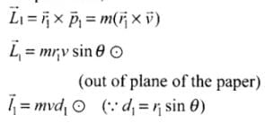
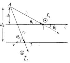
Q.2. Figure shows two identical particles 1 and 2, each of mass m, moving in opposite directions with same speed v along parallel lines.
At a particular instant, r1 and r2 are their respective position vectors drawn from point A which is in the plane of the parallel lines. Choose the correct options:
(a) Angular momentum l1 of particle 1 about A is l1 = mvd1
(b) Angular momentum l2 of particle 2 about A is l2 = mvr2
(c) Total angular momentum of the system about A is l = mv(r1 + r2)
(d) Total angular momentum of the system about A isl = mv(d2 − d1)
⊗ represents a unit vector coming out of the page.
⊗ represents a unit vector going into the page.
Ans. (a,b)
Solution.
The angular momentum L of a particle about the selected axis o f rotation is defined to be  where
where  is the position vector of the particle and
  is the linear momentum. The direction of
  is perpendicular to both
  by right hand thumb rule or screw rule.The angular momentum about point A, For particle 1.
Similarly, for particle 2,
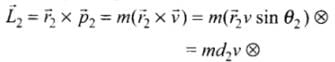
 (∴ r2 sinθ2 = d2) (into the plane of the paper)
∴ Total angular momentum
Hence (a) and (d) are correct options.
Q.3. The net external torque on a system of particles about an axis is zero. Which of the following are compatible with it ?
(a) The forces may be acting radially from a point on the axis.
(b) The forces may be acting on the axis of rotation.
(c) The forces may be acting parallel to the axis of rotation.
(d) The torque caused by some forces may be equal and opposite to that caused by other forces.
Ans. (a, b, c, d)
Solution.
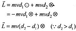
Torque on a system of particles about the axis of rotation is defined as 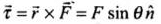 ............ (i)
where, θ is angle between  , and
, and  is a unit vector along the direction of torque and which is perpendicular to both
  .
.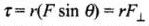
where is the component of F perpendicular to r.
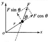 OR
OR
where is the perpendicular distance from the origin to the line of action of the force. It is also called the lever arm.
 (a) If the net external torque on a system of particles about an axis is zero, then
 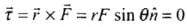 . When forces act radially, θ = 0 hence
 , so option (a) is correct.
(b) When forces arc acting on the axis of rotation, r = 0,
(c) When forces acting parallel to the axis of rotation θ = 0°,
(d) When torque by forces are equal and opposite,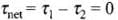
Important point: To get the direction where you can use right hand rule: Place the fingers of right hand along r and then curl them into F through the smaller angle between them, n is directed along the (stretched) thumb. For involving two dimensions only, can be replaced by sense of rotation, clockwise or anticlockwise; if the fingers of the right hand curl (while going from clockwise, torque is taken as clockwise and when they curl anticlockwise torque is taken as anticlockwise.)
Q.4. Figure shows a lamina in x-y plane. Two axes z and z′ pass perpendicular to its plane. A force F acts in the plane of lamina at point P as shown. Which of the following are true? (The point P is closer to z′-axis than the z-axis.)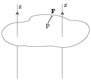 (a) Torque τ caused by F about z axis is along -kˆ.
(b) Torque τ′ caused by F about z′ axis is along -kˆ .
(c) Torque τ caused by F about z axis is greater in magnitude than that about z axis.
(d) Total torque is given be τ = τ + τ′.
Ans. (b,c)
Solution.
As we know that
And direction of z is perpendicular to plane of r and F by right hand thumb rule.
(a) Torque caused by force F about z-axis is in +k direction by right hand thumb rule.
(b) Similarly Torque caused by force F about z´-axis is in –k direction.
(c) r>r´ and θ>θ´
So, rFsinθ > r´Fsinθ´
Hence (d) There is no sense in adding torques about 2 different axes.
Q.5. With reference to Figure of a cube of edge a and mass m, State whether the following are true or false. (O is the centre of the cube.)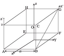 (a) The moment of inertia of cube about z-axis is Iz = Ix + Iy
(b) The moment of inertia of cube about z′ is I′z = Iz +
(c) The moment of inertia of cube about z″ is = Iz + 
(d) Ix = Iy
Ans. (b,d)
Solution.
Option a is false since perpendicular axes theorem is applicable only for laminar/planar objects.
Distance between z and z′ =
Applying parallel axis theorem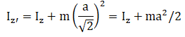
So option b is correct.
Z′′ and z are skew lines. That is, they are neither parallel nor perpendicular. So option c is incorrect as it is using parallel axis theorem.
Since the cube is symmetric, moment of inertia about x and y axis are equal. So, correct options are b and d.
VERY SHORT ANSWER TYPE QUESTIONS
Q.1. The centre of gravity of a body on the earth coincides with its centre of mass for a ‘small’ object whereas for an ‘extended’ object it may not. What is the qualitative meaning of ‘small’ and ‘extended’ in this regard?
For which of the following the two coincides? A building, a pond, a lake, a mountain?
Ans. Centre of gravity is the point through which the resultant of system of forces (due to weight) of all the particles constituting the body passes for all positions of body.
Centre of mass is a point where whole mass of a body can be concentrated.
When the vertical height of the object is very small as compared to earth’s radius, we call the object small otherwise it is extended.
(a) Building and pond are small object so their centre of mass and centre of gravity coincide.
(b) Deep lake and mountain are extended objects so their centre of mass doe of mass does not coincide with centre of gravity.
Q.2. Why does a solid sphere have smaller moment of inertia than a hollow cylinder of same mass and radius, about an axis passing through their axes of symmetry?
Ans. As we know that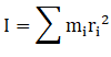
And all the mass in cylinder lies a distance R from axis of symmetry but most of the mass of solid sphere lies at smaller distance than R.
Therefore
Q.3. The variation of angular position θ, of a point on a rotating rigid body, with time t is shown in Figure. Is the body rotating clock-wise or anti-clockwise?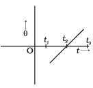 Ans. According to question slope of θ-t graph is positive, i.e
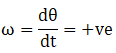
And therefore slope indicate anti-clockwise which is traditionally taken as positive.
Q.4. A uniform cube of mass m and side a is placed on a frictionless horizontal surface. A vertical force F is applied to the edge as shown in Figure. Match the following (most appropriate choice):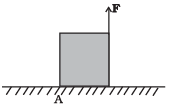
| mg/4 < F < mg /2 | Cube will move up |
| F > mg/2 | Cube will not exhibit motion |
| F > mg | Cube will begin to rotate and slip at A |
| F = mg/4 | Normal reaction effectively at a/3 from A, no motion |
Ans. From the problem = Torque due to F at A = aF
 = Torque due to mg at A = amg/2
Cube will not move if  =
=


So a-(ii)
Cube will rotate if 


So b-(iii)
If F>mg
Then cube will move up.
So, c-(i)
When the normal is a/3 from A.
So, for no rotation we balance the torque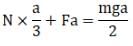
Balancing force
N = mg - F
Solving the above two equations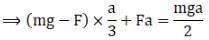

So, d-(iv)
Q.5. A uniform sphere of mass m and radius R is placed on a rough horizontal surface (Figure). The sphere is struck horizontally at a height h from the floor.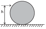 Match the following:
| h = R/2 | Sphere rolls without slipping with a constant velocity and no loss of energy. |
| h = R | Sphere spins clockwise, loses energy by friction. |
| h = 3R/2 | Sphere spins anti-clockwise, loses energy by friction. |
| h = 7R/5 | Sphere has only a translational motion, looses energy by friction. |
Ans.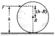 Applying conservation of angular momentum just before and after collision.
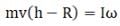
And as there is rolling without slipping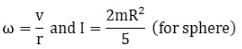
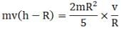
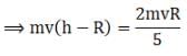
⇒ h - R = 2R/5
⇒ h = 7R/5
So, sphere will roll with slipping (no loss of energy) when h =7R/5
So, d-(i)
Torque due to applied force about centre of mass
If h=R then
Therefore, sphere will only have translational motion and loose energy by friction.
So, b-(iv)
If h>R, then torque is positive. Hence sphere will spin clockwise.
So, c-(ii)
If h<R, then torque is negative. Hence sphere will spin anticlockwise.
So, a-(iii)
Q.6. The vector sum of a system of non-collinear forces acting on a rigid body is given to be non-zero. If the vector sum of all the torques due to the system of forces about a certain point is found to be zero, does this mean that it is necessarily zero about any arbitrary point?
Ans. No, The sum of all the torques about the given certain point o is zero.
So,
Now, for any other arbitrary point sum of torques can be written as
In the above expression the second term may or may not vanish.
Q.7. A wheel in uniform motion about an axis passing through its centre and perpendicular to its plane is considered to be in mechanical (translational plus rotational) equilibrium because no net external force or torque is required to sustain its motion. However, the particles that constitute the wheel do experience a centripetal acceleration directed towards the centre. How do you reconcile this fact with the wheel being in equilibrium?
How would you set a half-wheel into uniform motion about an axis passing through the centre of mass of the wheel and perpendicular to its plane? Will you require external forces to sustain the motion?
Ans. As the system is the symmetrical system, the centripetal acceleration in a wheel arise due to internal elastic which exists in pair and cancel each other.
In the second part of question, in half wheel the distribution of mass about centre of mass is not symmetrical.
Therefore, the direction of angular momentum doesn’t coincide with the direction of angular velocity and hence an external torque is required to maintain rotation.
Q.8. A door is hinged at one end and is free to rotate about a vertical axis (Figure). Does its weight cause any torque about this axis? Give reason for your answer.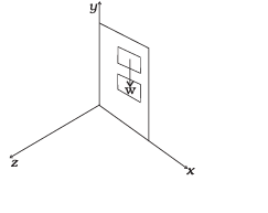 Ans. No, As we know that
So force can be produce torque only along the direction normal to itself. So, when the door in x-y plane, the torque produced by gravity can only be along be positive or negative z direction, never about an axis passing through y direction.
Q.9. (n-1) equal point masses each of mass m are placed at the vertices of a regular n-polygon. The vacant vertex has a position vector a with respect to the centre of the polygon. Find the position vector of centre of mass.
Ans. As we know that position of centre of mass is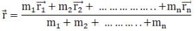
Since the centre of mass of regular n-polygon lies in the geometrical centre.
And n-1 equal point masses each of mass m are placed at n-1 vertices of n polygon. Therefore, it’s centre of mass will be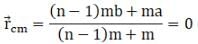
where b = distance of n-1 masses from centre of mass
(n-1)mb + ma = 0
b = -a/(n-1)
Negative sign indicates that is in direction opposite to
LONG ANSWER TYPE QUESTIONS
Q.1. Find the centre of mass of a uniform
(a) half-disc,
(b) quarter-disc.
Ans. (a) Let M be the mass of half disc and R be its radius.
Mass per unit length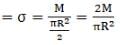
Let cut a semi-circular ring out of this semi disc at distance r and r+dr from centre.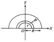 So, Area of element
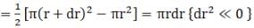
Mass of elementary ring = dm =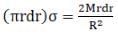
For this semi-circular ring centre of mass is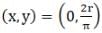
So,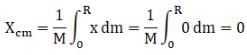
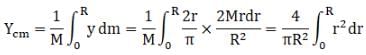
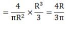
Hence centre of mass of semi-circular disc =
(b) Let M be the mass of quarter disc and R be its radius.
Mass per unit length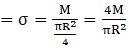
Similarly, as above part
Area of element =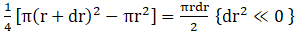
Mass of elementary ring = dm =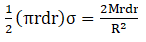
For this semi-circular ring centre of mass is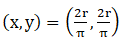
So,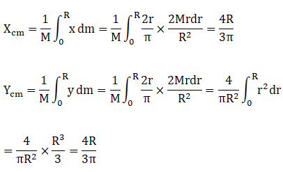
Hence centre of mass of Quarter disc =
Q.2. Two discs of moments of inertia I1 and I2 about their respective axes (normal to the disc and passing through the centre), and rotating with angular speed ω1 andω2 are brought into contact face to face with their axes of rotation coincident.
(a) Does the law of conservation of angular momentum apply to the situation? why?
(b) Find the angular speed of the two-disc system.
(c) Calculate the loss in kinetic energy of the system in the process.
(d) Account for this loss.
Ans.
(a) Yes, since there is no external torque on system.
All external forces act through axis of rotation, hence produce no torque.
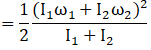
(b) When two of them coincide let ω be their common angular velocity.
Applying conservation of angular momentum
Final angular momentum= Initial angular momentum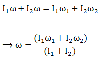
(c) 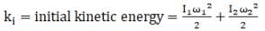
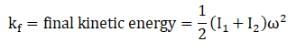
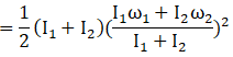
Change in kinetic energy
=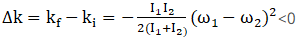
(d) The loss of kinetic energy is due to work against friction between two discs.
Q.3. A disc of radius R is rotating with an angular speed ωo about a horizontal axis. It is placed on a horizontal table. The coefficient of kinetic friction is µk.
(a) What was the velocity of its centre of mass before being brought in contact with the table?
(b) What happens to the linear velocity of a point on its rim when placed in contact with the table?
(c) What happens to the linear speed of the centre of mass when disc is placed in contact with the table?
(d) Which force is responsible for the effects in (b) and (c).
(e) What condition should be satisfied for rolling to begin?
(f) Calculate the time taken for the rolling to begin.
Ans. (a) As from the question the disc is rotating about its horizontal axis before coming in contact.
Hence it’s Vcom = 0
(b) Linear velocity of point at rim decreases due to force of friction.
(c) Linear speed of centre of mas of disc increases due to acceleration gained by it due to friction.
(d) Friction is responsible for effects in b and C.
(e) Rolling starts when Vcm = ωR
where ω is angular speed of disc.
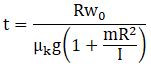
(f) Acceleration produced in centre of mass due to friction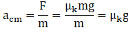
Angular acceleration produced by torque due to friction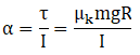
As we know that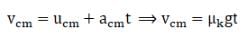
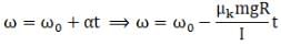
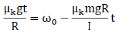
For rolling without slipping
So, 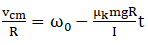
Q.4. Two cylindrical hollow drums of radii R and 2R, and of a common height h, are rotating with angular velocities ω (anti-clockwise) and ω (clockwise), respectively. Their axes, fixed are parallel and in a horizontal plane separated by (3R + δ ) . They are now brought in contact (δ → 0).
(a) Show the frictional forces just after contact.
(b) Identify forces and torques external to the system just after contact.
(c) What would be the ratio of final angular velocities when friction ceases?
Ans. 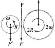 Here F and F′ are external forces through support.
Fnet = 0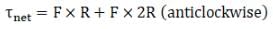
Let ω1 and ω2 be final angular velocities (anticlockwise and clockwise respectively)
Since there will be no friction both drum has same linear velocity.
Hence, VA = VB
Rω1 = Rω2
So,
Q.5. A uniform square plate S (side c) and a uniform rectangular plate R (sides b, a) have identical areas and masses (Figure).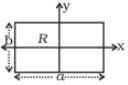
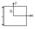 Show that
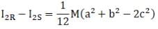
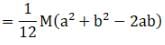
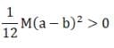
(i) IxR / IxS < 1;
(ii) IyR/ IyS > 1;
(iii) IZR/ IZs > 1.
Ans. According to question
Area of square=Area of rectangular plate
c2 = a x b
(a) As I ∝ area2 (as from diagram b<c)
(b) (as from diagram a>c)
(c) 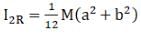
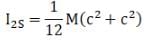
So, 


Q.6. A uniform disc of radius R, is resting on a table on its rim.The coefficient of friction between disc and table is µ (Figure). Now the disc is pulled with a force F as shown in the figure. What is the maximum value of F for which the disc rolls without slipping?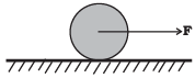
Ans. According to question, let
f = force of friction
F = applied force
a = acceleration produced
α = angular acceleration
So,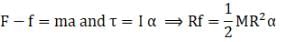
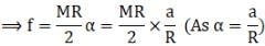
⇒ f = Ma/2
Solving above equations
We get f = F/3
And
Therefore
⇒ F ≤ 3μmg
|
119 videos|494 docs|98 tests
|
FAQs on NCERT Exemplar: System of Particles & Rotational Motion - Physics Class 11 - NEET
| 1. What is the difference between linear motion and rotational motion? |  |
| 2. How is the moment of inertia related to rotational motion? | |
| 3. How can we calculate the angular velocity of a rotating object? | |
| 4. What is the relationship between torque and rotational motion? | |
| 5. Can you explain the concept of angular momentum in rotational motion? | |


study material
,Previous Year Questions with Solutions
,Sample Paper
,Exam
,NCERT Exemplar: System of Particles & Rotational Motion | Physics Class 11 - NEET
,video lectures
,NCERT Exemplar: System of Particles & Rotational Motion | Physics Class 11 - NEET
,Viva Questions
,Important questions
,Extra Questions
,practice quizzes
,Summary
,NCERT Exemplar: System of Particles & Rotational Motion | Physics Class 11 - NEET
,Free
,past year papers
,ppt
,Semester Notes
,shortcuts and tricks
,MCQs
,Objective type Questions
,mock tests for examination
;


NCERT Exemplar: System of Particles & Rotational Motion Free PDF Download
Importance of NCERT Exemplar: System of Particles & Rotational Motion
NCERT Exemplar: System of Particles & Rotational Motion Notes
NCERT Exemplar: System of Particles & Rotational Motion NEET Questions
Study NCERT Exemplar: System of Particles & Rotational Motion on the App
|
© EduRev
|
Education Revolution
|


|


