
- Whenever there is a relative motion between a loop (or coil) and a magnet, an emf is induced in the loop (or coil) which is called induced emf. This phenomenon is called as electromagnetic induction.
- Magnetic flux linked with a coil
(i) Flux ϕ = NBAcosθ where
B = strength of magnetic field
N = number of turns in the coil
A = area of surface
θ = angle between normal to area and field direction.
(ii) When plane of coil is perpendicular to B, i.e. θ = 0°, ϕ = NBA (maximum value).
(iii) When plane of coil is parallel to B, i.e. θ = 90°,
ϕ = 0 (minimum value)
(iv) S.I. unit of ϕ = weber
c.g.s unit of ϕ = maxwell
1 weber = 108 maxwell.
(v) Dimensional formula of magnetic flux
[ϕ] = [ML2T-2A-1]. - Faraday's laws of electromagnetic induction
(i) Whenever magnetic flux linked with a circuit (a loop of wire or a coil or an electric circuit in general) changes, induced emf is produced.
(ii) The induced emf lasts as long as the change in the magnetic flux continues.
(iii) The magnitude of induced emf is directly proportional to the rate of change of the magnetic flux linked with the circuit.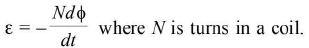
- By Faraday's second law of induction, ε = -dϕ/dt
Apply it to the coil.
Induced e.m.f. ε depends on rate of change of magnetic flux linked with the coil.
Flux ϕ = NBAcosθ where
B = strength of magnetic field
N = number of turns in the coil
A = area of surface
θ = angle between normal to area and field direction.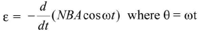
Induced e.m.f. ε depends on N, B, A and ω. - Lenz's Rule
States that the induced current produced in a circuit always flows in such a direction that it opposes the change or the cause that produce it. - Fleming's right hand rule
- Motional E.M.F.
When a conductor of length l moves with a velocity v in a magnetic field B, so that magnetic field is perpendicular to both the length of the conductor and its direction of motion, the magnetic Lorentz force on the conductor gives rise to e.m.f. Mathematically, ε = Blv. - Eddy currents/Focault's currents
Currents induced in conductor, when placed in a changing magnetic field are also known as Focault's currents. - Self inductance
The phenomenon, according to which on opposing induced emf is produced in a coil as a result of change in current or magnetic flux linked with the coil is called self-inductance. - Coefficient of self induction or self inductance L
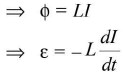
- Self inductance/coefficient of self induction
(i) The self inductance L depends on geometry of coil or solenoid and the permeability of the core material of the coil or solenoid.
(ii) Unit of L = henry.
(iii) Dimensions of inductance =
(iv) For a small circular coil,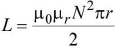
(v) For a solenoid,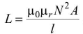
(vi) For two coils connected in series when
- Current flows in same direction in both,
L = L1 + L2 + 2 M
- When currents flow in two coils in opposite directions
L = L1 + L2 - 2 M
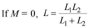
If M = 0 ,L = L1 + L2
(vii) For two coils connected in parallel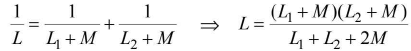
(viii) Self inductance of a toroid,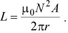
- Mutual inductance (M)
(i) Mutual inductance of two coils is numerically equal to magnetic flux linked with one coil, when a unit current flows through the neighbouring coil.
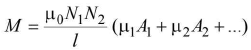
(ii) For two long co-axial solenoids, each of length l, common area of cross-section A wound on air core,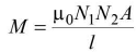
(iii) For two coupled coils, M = where K denotes the coefficient of coupling between the coils.
(iv) If K = 1, the coils are said to be tightly coupled such that magnetic flux produced in primary is fully linked with the secondary. = maximum value o f M.
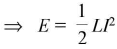
 - Energy stored in an inductor
- Induced emf due to rotation and translation
(i) A conducting rod rotates in a perpendicular magnetic field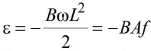 where f = frequency of rotation
A = area swept by rotating rod = πL2
L = length of rod, ω = angular/rotational speed
(ii) A disc rotates in a perpendicular magnetic field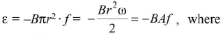
A = πr2 = area of disc, ω = angular speed of disc
(iii) A rectangular coil moves linearly in a field when coil moves with constant velocity in a uniform magnetic field, flux and induced emf will be zero.
(iv) When a coil is displaced in a field B, ε = -Bvl where v = velocity of coil.
(v) A rod moves, at an angle θ with the direction of magnetic field, with velocity
ε = -B/vsinθ
ε = -Blv when rod moves along normal to the field. - An emf is induced in the following cases:
(i) When a train moves horizontally in any direction.
(ii) When an aeroplane flies horizontally.
(iii) When a conductor falls freely in east-west direction.
(iv) When an aeroplane takes off or lands with its wings in east-west direction.
(v) The plane of orbit of a metallic satellite is inclined to the equatorial plane at any angle.
(vi) When a magnet is moved with respect to a coil, an emf is induced in the coil.
(vii) When a current carrying coil is moved with respect to a stationary coil, a current is induced in the stationary coil.
(viii) When strength of current flowing in a coil is increased or decreased induced current is developed in the coil in same or opposite direction.
Growth and decay of current
- Growth of current in inductive circuit
(i) The value of current at any instant of time t is given by
I = I0(1 - e -Rt/L) where
I0 = maximum/final current
R = total resistance of circuit
(ii) If t = L/R
I = 0.63I0 = 63% I0 = L/R = time constant of circuit.
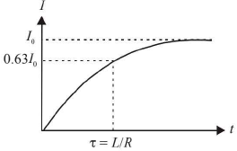
(iii) Inductance acts as electrical inertia. It opposes growth of current as well as decay of current. - Decay of current in inductive circuit
(i) During decay, current at any instant of time is given by
I = I0 -e-Rt/L
(ii) If t = L/R = = time constant of circuit,
I = I0/e = 37% I0.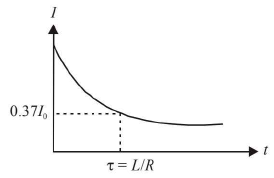
Charge and discharge of a capacitor
- Charge of condenser
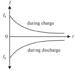
(i) Instantaneous charge : When the key K1 is closed, the capacitor gets charged. Finite time is taken in the charging process.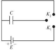
Instantaneous charge = q
∴ q = q0 [ l - e-(t/RC]
where q0 = maximum final value of charge at t = infinity and R = resistance of whole circuit.
The equation reveals that q increases exponentially with increase of time.
(ii) If t = RC = = time constant.
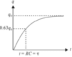
or q = q0(1 - 0.37) = 0.63q0
or q = 63% of q0.
Time = RC is known as time-constant.
(iii) Dimensions of RC = [T] = [M0L0T1]
(iv) Potential difference across condenser plates = V
∴ V= V0[1 - e-(t/RC)]
(v) I = I0[e-t/RC)].
If t = RC, then transient current I is given by
I = I0e = 0.37 I0
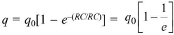
or 7=37% of I0. - Discharge of condenser
If key K1 is opened and key K2 is closed, then the capacitor gets discharged.
(i) Instantaneous charge : q = q0e-(t/RC) The charge decays exponentially.
(ii) Time constant = 
If t = RC = 
q = q0/e = 0.37 q0 = 37% o f q0.
The time constant is that time during which the charge on capacitor plates, during discharge process, decays to 37% of its maximum value.
(iii) The dimensions of RC are those of time i.e. M0L0T1.
(iv) The potential difference across the capacitor plates at any instant of time is given by
V= V0e-(t/RC)
(v) Transient current I at any instant of time is given by I = -I0 e-(t/RC)
The current in the circuit decays exponentially but its direction is opposite to that of charging current.
Alternating current and alternating e.m.f
- Instantaneous values (7) and (E)
I = I0sinωt or I = I0cosωt
E = E0sinωt or E = E0cosωt where
I, E = instantaneous values of current and e.m.f.
I0, E0 = peak values of current and e.m.f.
ω = angular velocity
ω = 2πf where f denotes frequency.
ω = 2π/T where T denotes periodic time. - Mean or average values
(i) In first half-cycle,
(ii) In second half-cycle,
(iii) Over a complete cycle,
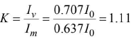
Im = 0 and Em = 0. - Root mean square (RMS = r.m.s.) value
(i) RMS value is also known as virtual value or effective value.
(ii) All A.C. instruments measure virtual value.
(iv)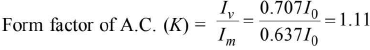
- Reactance
(i) It is the opposition offered to A.C. by a coil of inductance L or by a capacitor of capacitance C.
(ii) Reactance arises on account of induction effects. - Inductive reactance (XL)
(ii) Alternating current lags behind the alternating e.m.f. applied to a pure inductor by phase angle of 90°.
(iii) For direct current (d.c.), frequency f = 0.
∴ XL = zero.
An inductor thus behaves like a perfect conductor for d.c.
(iv) For a.c., higher the frequency f greater is the inductive reactance.
(v) Average power over one full cycle of a.c.
Pav = Ev Iv cosθ = EvIv cos90° = zero.
(vi) Energy stored in inductor =
(vii) Choke coil: It is a pure inductance coil. Since power consumed in it is zero, the current in choke coil is known as wattless current.
(viii) Susceptance =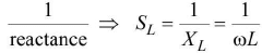
It is measured in siemen or (ohm)-1. - Capacitative reactance (Xc)
(i)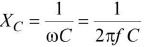
(ii) Alternating current leads the alternating e.m.f. in a pure capacitor by phase angle of 90°.
(iii) For d.c .,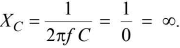
A condenser blocks d.c.
(iv) For a.c., higher the frequency/, lower is the capacitative reactance.
(v) Average power or true power over one full cycle of a.c.
Pav = EvIv cosθ = EvIv cos90° = zero.
(vi) Energy stored in a capacitor =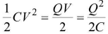
(vii) Susceptance is reciprocal of reactance.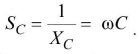
Susceptane is measured in (ohm)-1 or siemen. - Impedance
(i) The total effective opposition in LCR circuit is called impedence (Z).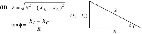
ϕ = angle by which e.m.f. leads the current in LCR circuit,
(iii) Admittance (K)
Reciprocal of impedence is called admittance. K =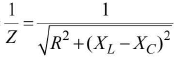
It is measured in (ohm)-1 or siemen. - Power in a.c. circuit
(i) Instantaneous power = Pin = El
Pin = (E0 sinωt) I0 sin((ωt ± θ)
(ii) Average power or true power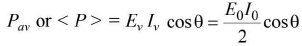
(iii) Apparent power (Pv)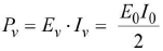
It is equal to maximum value of average power. - Power factor
(i) Power factor of an a.c. circuit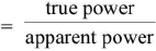
⇒ Power factor = cosθ = R/Z.
(ii) It is a unitless and dimensionless quantity.
(iii) Its value lies between 0 and 1.
(iv) Power lost in the circuit is the meaning of power factor of the circuit. - Purely resistive circuit
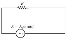
(i) E = E0sinωt
(ii) I = I0sinωt
(iii) Phase difference between I and E is zero.
(iv) Peak current I0 = E0/R
(v) Average power = true power = Ev Iv
(v) Power factor = cosθ = cos0 = 1. - Pure inductive circuit
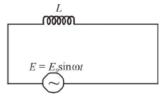
(i) E = E0sinωt
(ii) I = I0sin
(iii) Current lags behind e.m.f. by π/2 or e.m.f. leads over current by π/2
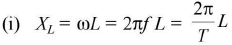
(iv) Reactance XL = ωL = 2πf L
(v) Peak current I0 = E0/XL
(vi) Average power = zero.
(vii) Power factor = cosθ = cos90° = zero. - Pure capacitative circuit

(i) E = E0sinωt
(ii) I = I0 sin
(iii) Current leads the e.m.f. by π/2 or e.m.f. lags behind the current by π/2
(iv) Reactance =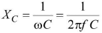
(v) Peak current = I0 = E0/XC
(vi) Average power = zero
(vii) Power factor = cosθ = cos90° = zero. - Pure capacitative circuit
(i) E = E0sinωt
(ii)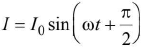
(iii) Current leads the e.m.f. by π/2 or e.m.f. lags behind the current by π/2
(iv) Reactance =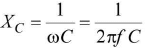
(v) Peak current = I0 = E0XC
(vi) Average power = zero
(vii) Power factor = cosθ = cos90° = zero. - L-R circuit
(i) Equations of E and I
E = E0sinωt
I = I0sin(ωt - θ)
Current I lags behind the applied e.m.f. E by θ.
It means that the e.m.f. leads over current by θ.
Equations can also be represented as
E = E0sin(ωt + θ) and
I = I0sinωt.
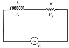
(ii) Resultant voltage
(iii) Power factor (cosθ) =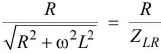
(iv) Average power < P >
<P> = ErmsIrms cosθ. - R-C circuit
(i) Equations of E and I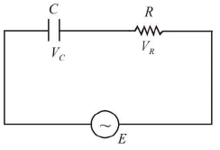
E = E0sinωt
I = I0 sin (cot + θ)
or E = E0sin((ωt - θ),
I = I0sinωt.
emf E lags behind the current I by θ
or current I leads over e.m.f. by θ
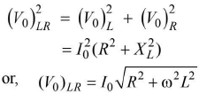
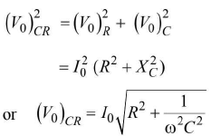
(ii) Resultant voltage (V0)CR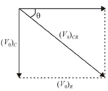
(iii) Power factor (cosθ)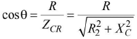
(iv) Average power, < P >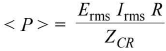
- L-C circuit
(i)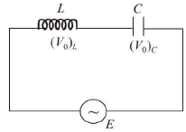
(ii) Resultant voltage
( V0)LC= ( V0)L ~ ( V0)C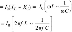
- Phase relations
(i) The phase difference between VL and VC is 180° i.e. they are in mutually opposite phase.
(ii) VL leads I by a phase angle of 90°.
(iii) VC lags behind I by a phase angle of 90°.
(iv) I will lead E by 90° if XC > XL.
(v) I will lag behind E by 90° if XC < XL. - Impedence or reactance
(i) Z = XL ~ XC
(ii)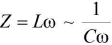
(iii)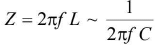
(iv) If XL > XC, then Z = XL - XC =
(v) I f XL < XC, then Z = XC-XL =
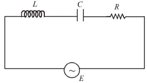
(vi) If XL, = XC , then Z = 0. - LCR series circuit
(i) The alternating e.m.f. leads/lags behind the current by a phase angle Φ given by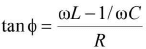
(ii) The e.m.f. leads the current, if ωL>1/ω C and it lags behind the current, if ω L< 1/ωC.
(iii) Impedance of LCR-circuit,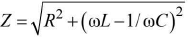
(iv) Power factor, cost Φ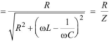
- Series resonant circuit
(i) L, C and R are connected in series.
(ii) Condition of resonance is XL = XC.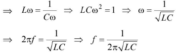
This means that frequency of a.c. applied to circuit becomes equal to natural frequency of energy oscillations in the circuit.
(iii) Z = R at resonance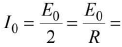 circuit admits maximum current.
The following figures indicate variation of Z and current with frequency.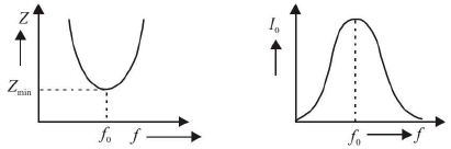
(iv) Acceptor circuit : Series resonance circuit is known as acceptor circuit.
(v) Sharpness at resonance or Q-factor : Q should be higher for sharper resonance.
- Parallel resonant circuit
(i) It is known as rejector circuit.
(ii) L and C are connected in parallel with each other.
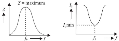
(iii) At resonance, XL = XC
Impedence Z is maximum.
Current I0 is minimum. - The figures indicate the variations.
Transformer
- It is based on the phenomenon of mutual induction between two coils known as the primary coil and the secondary coil.
- It is used for transmission of a.c. over long distances at high voltages. The energy losses and cost of transmission are reduced by this device.
- Step-up transformer:
(i) The output voltage Es across secondary coil is greater than input voltage Ep in primary coil.
(ii) But Is < Ip
(iii) Ns > Np where N denotes the number of turns in the coils.
(iv)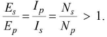
- Step-down transformer
(i) The output voltage Es < Ep
(ii) The output current Is > Ip
(iii) The number of turns NS < NP
(iv)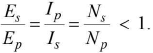
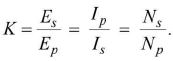
- Transformation ratio (K)
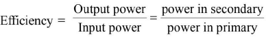
Efficiency of transformer =

- For an ideal transformer,
output power = input power
ESIS = EPIP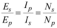
But in practice, these are losses.
Output power < input power.
The losses are discussed along with remedy. - Copper losses
(i) Windings are made of copper wire. Energy is lost as heat in resistance of copper wire.
(ii) It is reduced by use of thick wires of copper. - Iron losses/eddy current losses
(i) Energy is lost due to eddy currents in the core of transformer.
(ii) It is reduced by using laminated soft iron core. - Flux leakage
(i) Some magnetic flux leaks in air between primary and secondary coils.
(ii) It is reduced by winding the secondary coil over a primary coil using insulator between them. - Hysteresis loss
(i) The core is magnetised and demagnetised and energy is lost as heat.
(ii) It is reduced by using soft iron core.
Various material points about transformer
- There is a phase difference of it radian between ES and Ep. Obviously they are in opposite phases.
- Transformer, a device based on mutual induction, converts magnetic energy into electrical energy.
- Transformer does not amplify power as a vacuum tube (triode) does.
Law of conservation of energy holds good for a transformer. - It does not operate on d.c. or direct voltages. It operates only on alternating voltages at input as well as at output.
- Frequency of output voltage across secondary coil is same as that of input voltage across primary coil.
Power available in secondary can never be greater than power fed in primary.
At the most, efficiency = 1 = 100%.
Generally, efficiency ranges from 70% to 90%.
Some salient features about a.c., transformer and inductance
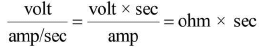
- The dimensions of L/R, RC and
 are the dimensions of time. Their reciprocal have dimensions of frequency.
 - Form factor of a.c. is K =
- The direction of induced e.m.f. depends on
(i) direction of magnetic flux
(ii) rate of change of magnetic flux i.e. dty/dt is increasing or decreasing - An induction coil generates high voltages of the order of 105 volts from a battery. It is based on the phenomenon of mutual induction.
- A choke coil is a pure inductor. Average power consumed per cycle is zero in a choke coil.
- For reducing low frequency a.c., choke coil with laminated soft iron cores are used.
- For reducing high frequency a.c., air cored chokes are used.
- A d.c. motor converts d.c. energy from a battery into mechanical energy of rotation.
- A motor starter is a variable resistance connected in series with the motor coil. It protects the motor from damage when it is switched on.
- A d.c. dynamo/generator produces d.c. energy from mechanical energy of rotation of a coil.
- An a.c. dynamo/generator produces a.c. energy from mechanical energy of rotation of a coil.
- Effective current
(i) The component of a.c. which remains in phase with the alternating e.m.f. is defined as the effective current.
(ii) The power lost due to effective current is given by EVIV cosθ.
(iii) The peak value of effective current is I0cosθ. Its r.m.s. value is
- Lenz's law is based on the law of conservation of energy.
- henry =
- If a solenoid is placed partly in different media, then
- Reciprocity relation : Mutual inductance M depends on two coils. It does not matter which one of them acts as the primary or the secondary coil. The relation
 for a solenoid is known as reciprocity relation.

shortcuts and tricks
,Chapter 16 - Electromagnetic Induction and Alternating Current - JEE
,MCQs
,Viva Questions
,Chapter 16 - Electromagnetic Induction and Alternating Current - JEE
,study material
,ppt
,practice quizzes
,video lectures
,Previous Year Questions with Solutions
,Sample Paper
,Semester Notes
,Free
,Important questions
,Objective type Questions
,Extra Questions
,Chapter 16 - Electromagnetic Induction and Alternating Current - JEE
,mock tests for examination
,Summary
,past year papers
,Exam
;


Chapter 16 - Electromagnetic Induction and Alternating Current Free PDF Download
Importance of Chapter 16 - Electromagnetic Induction and Alternating Current
Chapter 16 - Electromagnetic Induction and Alternating Current Notes
Chapter 16 - Electromagnetic Induction and Alternating Current JEE Questions
Study Chapter 16 - Electromagnetic Induction and Alternating Current on the App
|
© EduRev
|
Education Revolution
|


|


