Levelling & Contouring

Levelling
Levelling is the branch of surveying concerned with the determination of elevations (heights) of points on the earth's surface and the differences in elevation between them. Its primary purpose is to establish a horizontal line of sight from which reduced levels (R.L.) of points are found. Levelling is used for establishing bench marks, preparing contour maps, designing roads, canals and other engineering works where vertical control is essential.
Definitions
- Reduced level (R.L.): The elevation of a point measured with respect to a chosen datum, commonly Mean Sea Level (MSL) or an assumed datum. R.L. of a point = height of datum + vertical distance of the point above/below datum.
- Bench mark (B.M.): A relatively permanent reference point whose elevation with respect to a chosen datum is known. A bench mark is used as the starting reference for levelling and as a closure check during surveys.
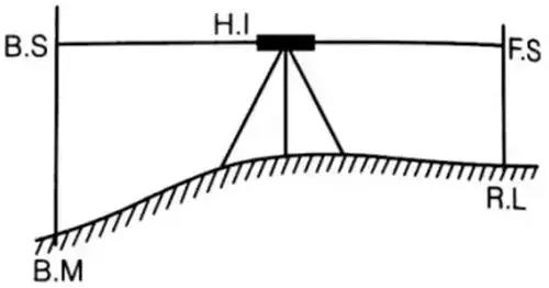
- Back sight (B.S.): The first staff reading taken on a point of known elevation after the instrument is set up. It is treated as a positive sight (also called plus sight).
- Fore sight (F.S.): The last staff reading taken from an instrument station before moving the instrument to a new station. It is treated as a negative sight (also called minus sight).
- Intermediate sight (I.S.): Any staff reading taken between the back sight and the fore sight; these are used to determine R.L. of intermediate points.
- Height of instrument (H.I.): The elevation of the line of sight of the instrument above the datum. It is obtained by adding the R.L. of a benchmark or point and the back sight on that point.
Formulae:
H.I. = R.L. of reference point + B.S.
R.L. of any point = H.I. - F.S.
Instruments commonly used in levelling
- Dumpy level, tilting level, auto-level (spirit level), digital level.
- Theodolite or total station used as a levelling instrument where precise angular control is required.
- Levelling staff (graduated staff) or rod for taking readings.
Methods of computing reduced levels
Two commonly taught methods are the Height of Instrument (H.I.) method and the Rise and Fall method. Both use the same observations but differ in arithmetic procedure.
Height of instrument method
- Set up the instrument and take a back sight on a point of known R.L.; compute H.I. = R.L. + B.S.
- For each intermediate point, compute R.L. = H.I. - I.S.
- When a fore sight is taken to move the instrument, compute R.L. = H.I. - F.S. for that point; then shift the instrument and repeat.
Arithmetic check (H.I. method):
Sum of all back sights - Sum of all fore sights = Last R.L. - First R.L.
Rise and Fall method
- Compute the difference between successive staff readings to determine whether there is a rise or a fall.
- If the reading decreases in the forward direction, record the change as a rise; if it increases, record it as a fall.
- R.L. of next point = R.L. of previous point + rise - fall (as applicable).
Arithmetic check (rise and fall):
Sum of rises - Sum of falls = Last R.L. - First R.L.
Checks and observatory practice
- Always begin levelling from a known bench mark and close the level loop on a second bench mark to detect mistakes.
- Carry out reciprocal readings or repeat critical setups to check for instrument errors.
- Maintain a clear, tabulated field book showing station, staff readings (B.S., I.S., F.S.), H.I., R.L., and rise/fall where appropriate.
Reciprocal levelling
Reciprocal levelling is used when two instrument stations are separated by an obstacle (a river, deep valley or long distance) that prevents a direct line of sight with acceptable accuracy. The method reduces the effects of collimation error (an inclined line of sight) and compensates for curvature and refraction to a large extent.
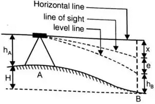
Conceptually, observations are made from both ends of the line between the two points A and B:
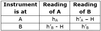
- Set up the instrument at A and take staff readings on A and B; denote these readings as hA and hB.
- Set up the instrument at B and take staff readings on A and B; denote these readings as h' A and h' B.
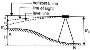
If the instrument and the line of sight were perfect and there were no curvature/refraction effects, the difference of staff readings observed with the instrument at A would equal that observed with the instrument at B, i.e.
hA - hB = h' A - h' B
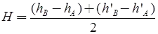
When errors exist, the average of the two independently observed differences is taken to give the best estimate of the true difference of reduced levels between A and B. Averaging cancels most of the effect of an inclined line of sight (collimation error) because that error reverses sign when instrument position is changed.
Procedure summary:
- Take readings from both ends; compute the difference of readings for each instrument setup.
- Average the two differences to obtain the true difference of R.L. between points A and B.
- Apply curvature and refraction corrections for long sights if required (see next section).
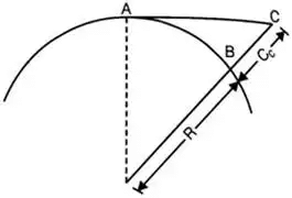
Curvature and refraction corrections
For long sight distances, the earth's curvature and atmospheric refraction produce systematic errors in levelling measurements. The corrections are treated conventionally as follows.
Curvature correction (CC):
CC = - d² / (2R)
Here, d is the horizontal distance between the two points; R is the radius of the earth.
With R = 6 370 km, the curvature correction may be written in the practical form:
CC = -0.07849 d²
Here CC is in metres when d is in kilometres. The negative sign indicates that the curvature causes the apparent level line to be above the true horizontal (observed staff appears lower), so a negative correction is applied to observed differences.
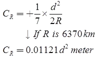
Refraction correction (CR):
Empirically for normal atmospheric conditions, refraction reduces the curvature error by about one-seventh. Thus
CR = + (1/7) CC
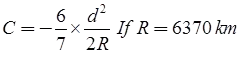
Combined correction due to curvature and refraction (C):
C = CC + CR = -(6/7) CC
Using the numerical constant given earlier,
C = -0.06728 d² (metres), where d is in kilometres.
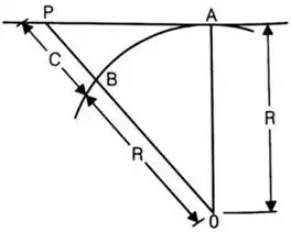
Distance of visible horizon:
When both curvature and refraction are taken into account, the distance d (in kilometres) to the visible horizon from an eye or instrument at height C (in metres above the horizon) can be approximated by the expression
d = 3.8553 √C
Here C is the height in metres. This approximate relation is useful when estimating whether curvature/refraction corrections are necessary for a particular sight distance.
Practical notes on curvature and refraction
- For short sights (a few hundred metres), curvature and refraction corrections are negligible and commonly ignored.
- For precise levelling over long distances, include combined C correction for each sight or use reciprocal levelling to reduce their effect.
- Atmospheric conditions affect refraction; unusual temperature gradients can change the standard 1/7 factor.
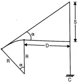
Sensitiveness of the bubble tube
Sensitiveness of a spirit (bubble) level is defined as the angular value corresponding to one division of the bubble tube scale. It expresses how much angle change is produced by moving the bubble by one division.
Let S = difference between two staff readings corresponding to the movement of the bubble by n divisions when the staff is held at a distance D from the instrument.
One way to express the angular value (α') of one division is:
α' = (S / (n D)) radians
To convert radians into seconds of arc multiply by 206265:
α' (seconds) = (S / (n D)) × 206265
Another geometric expression for the angular value is
α' = l / R (radian)
where l is the length of one division on the bubble tube and R is the radius of curvature of the bubble tube. Conversion to seconds of arc may be performed as above.
Practical implications:
- A more sensitive bubble (small α') allows finer adjustment of the instrument and more precise levelling but may be more difficult to set in windy conditions.
- Manufacturers quote sensitivity as the displacement of the bubble corresponding to a given angular tilt (e.g., 2 mm per 20 seconds), and surveyors select instruments appropriate to the accuracy required.
Contouring
Contouring is the graphic representation of elevations by drawing lines joining points of equal elevation. These lines, called contours, show the shape and slope of the land surface on a two-dimensional map.
Basic terms
- Contours: Imaginary lines on a map that join points of equal elevation above the chosen datum.
- Contour interval (C.I.): The vertical distance between two successive contour lines; it is constant for a given map.
- Index contour: A contour line drawn heavier and usually labelled with its elevation (e.g., every fifth contour).
- Intermediate contour: The lighter contours between index contours.
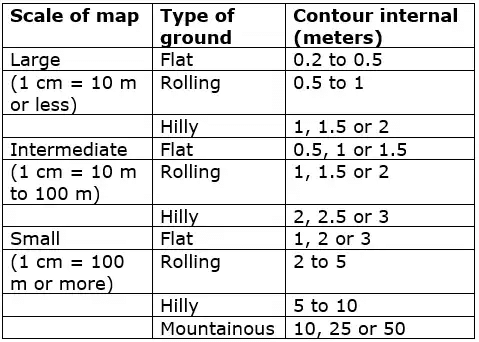
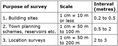
Selection of contour interval
Choice of contour interval depends on the ground relief and the scale of the map. Smaller contour intervals are used for fairly flat ground or where detailed vertical control is required; larger intervals for steep or mountainous regions.
Suggested practical rules and relations:
- Contour interval = (25 / number of cm per km) metres (when using metric scales)
- Contour interval = (50 / number of inches per mile) feet (for imperial-scale maps)
These formulae give a guideline to relate map scale to an appropriate contour interval so that contours are neither too dense nor too sparse on the sheet.
Characteristics and rules of contours
- Contour lines join points of equal elevation; they never cross each other except on vertical cliffs where convention varies.
- Contours form closed loops either on the map sheet or beyond its boundary.
- Contours indicate slope: closely spaced contours represent steep slopes; widely spaced contours indicate gentle slopes.
- Contours point upstream across a valley (the contour bends upstream) and form V-shaped patterns; the apex of the V points towards higher ground.
- Contours on a hill form concentric closed loops with elevation increasing towards the centre; contours on a depression are marked with hachures or tick marks pointing towards lower elevation.
- Index contours are labelled with elevation for easy reading; intermediate contours are unlabelled.
Methods of preparing contours
- Direct contouring by levelling: obtain a grid of spot levels by levelling and draw contours by interpolation between spot elevations.
- Indirect contouring from cross-sections: prepare cross-sections at regular intervals and interpolate contours by joining points of equal elevation on successive sections.
- Use of total station or GPS: modern surveys collect dense point elevations and contours are generated by computer using interpolation and contouring algorithms (TIN, DEM).
Applications of contours
- Topographic mapping and site investigation for engineering works.
- Alignment and design of roads, railways, canals and pipelines.
- Calculation of cut and fill (earthwork quantities).
- Drainage design and watershed analysis.
- Site selection and landscape planning.
Practical advice for field contouring
- Choose a contour interval that balances readability and accuracy for the map scale and relief.
- Maintain systematic levelling or profiling to gather sufficient spot elevations for smooth interpolation.
- Mark index contours clearly on field sheets and label elevations to avoid ambiguity during drafting.
- Verify critical contours by re-levelling or by reciprocal checks where accuracy is essential.
Summary (optional): Levelling establishes vertical control and reduced levels using systematic observations and arithmetic methods (H.I. and rise-and-fall). Reciprocal levelling and curvature/refraction corrections are used for long sights. Contouring converts spot elevations into continuous representations of terrain and is essential for planning and design in civil engineering.
FAQs on Levelling & Contouring
| 1. What's the difference between levelling and contouring in surveying? |  |
| 2. How do I find the reduced level of a point using the height of instrument method? | |
| 3. Why do contour lines never cross each other on a topographical map? | |
| 4. What causes errors in levelling surveys and how do I minimize them? | |
| 5. How are contour intervals decided, and what interval should I use for hilly terrain? | |


