Compression Members | Design of Steel Structures - Civil Engineering (CE) PDF Download
Strength of an Axially Loaded Compression Member
The maximum axial compressive load P
P = σac x A where, P = axial compressive load (n)
σac = permissible stress in axial compression (MPa)
A = gross-sectional area of the member (mm2)
IS800-1984 uses the Merchant Rankine formula for σac, which is given as

Where, fcc = elastic critical stress in compression = 
λ = slenderness ratio = I/r
l = effective length of the compression member.
r = appropriate radius of gyration of the member (minimum value)
E = modulus of elasticity of steel = 2 x 10⁵ MPa
n = a factor assumed as 1.4
Maximum Slenderness Ratio (Clause 3.7.1 IS: 800-1984)

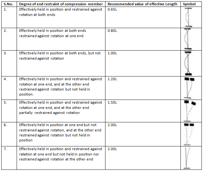
Effective Length
Table: (Effective length of compression members of constant dimensions (Clause 5.2.2 IS: 800-1984)
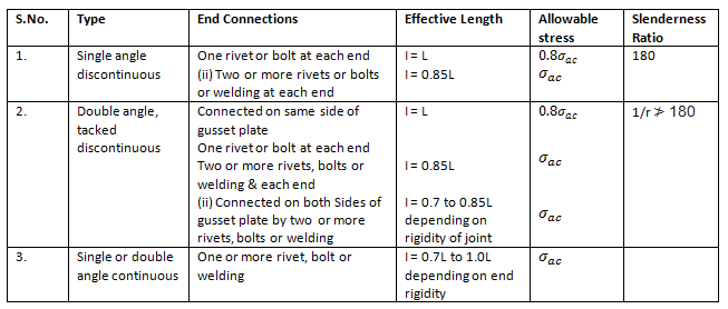
Angle struts
- The slenderness ratio (λ=I/r) should not exceed the values given in Table.
Table: Angle Struts (Clauses 5.5, IS: 800 – 1984)
Built-up Compression Member
Tacking Rivets
- The slenderness ratio of each member between the connections should not be greater than 40 nor greater than 0.6 times the most unfavourable slenderness ratio of the whole strut. In no case should the spacing of tacking rivets in a line exceed 600 mm for such members, i.e. two angles, channels or tees placed back-to-back.
- For other types of built-up compression members, say where cover-plates are used, the pitch of tacking rivets should not exceed 32 t or 300 mm, whichever is less, where t is the thickness of the thinner outside plate. When plates are exposed to the weather, the pitch should not exceed 16 t or 200 mm, whichever is less.
- The diameter of the connecting rivets should not be less than the minimum diameter given below.

Design of Compression Members
The following steps are followed for designing an axially loaded compression member:
- Assume some value of permissible compressive stress 𝛔ac and calculate the approximate gross sectional area A required

For single-angle-channel-or I-section (low loads), 80 MPa, and for built-up sections (heavy loads), 110 MPa may be assumed initially as permissible compressive stress. - Choose a trial section having area = Aapprox.
- Determine the actually permissible stress corresponding to the maximum slenderness ratio l/r of the trial section.
- Calculate the safe load to be carried by the trial section by multiplying the actual permissible stress by the area of the trial section.
If the safe load is equal to or slightly more than the actual load, the trial section is suitable for selection. Otherwise, the above steps should be repeated. - Check the slenderness ratio.
Lacings
1. General requirements
- The radius of gyration about the axis ⊥ to the plane of lacing
 radius of gyration about the axis in the plane of lacing.
 - The lacing system should not be varied throughout the length of the strut as far as practicable.
- The single-laced system on opposite sides of the main components should preferably be in the same direction so that one be the shadow of the other.
2. Design Specification
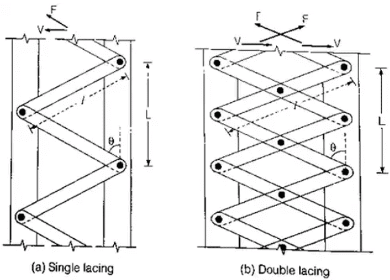
- The angle of inclination of the lacing with the longitudinal axis of the column should be between 40° to 70°.
- The slenderness ratio le/r of the lacing bars should not exceed 145. The effective length le of the lacing bars should be taken as follows:

- For local Buckling criteria
 Where L = distance between the centres of connections of the lattice bars to each component as shown in fig.
rcmin = minimum radius of gyration of the components of the compression member. - Minimum width of lacing bars in riveted construction should be as follows:

Minimum thickness of lacing bars: for single lacing
 for double lacing riveted or welded at the intersection
where, l = length between inner and rivets as shown in fig. - The lacing of compression members should be designed to resist a transverse shear, V = 25% of axial force in the member.
(i) For a single lacing system on two parallel faces, the force (compressive or tensile) in each bar, F = V / 2sinθ
(ii) For a double lacing system on two parallel planes, the force (compressive or tensile) in each bar, F = V / 4sinθ
(iii) If the flat lacing bars of width b and thickness t have rivets of diameter d then, Compressive stress in each bar = force/gross area = F / b x t σ∝
σ∝
(iv) Tensile stress in each bar = force/net area = F / (b - d) x t σ∝
σ∝ - End Connections:
(i) Riveted Connection: Riveted connections may be made in two ways, as shown in Fig. (a) and (b).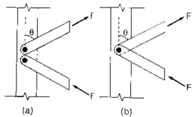 For case (a),
Number of rivets required = F / Rivet value
For case (b),
Numbers of rivets required = 2Fcos / Rivet value - Welded connections
(i) Lap joint: Overlap image041 times thickness of bar or member, whichever is less.
(ii) Butt joints: Full penetration butt weld of fillet weld on each side. The lacing bar should be placed opposite to the flange or stiffening member of the main member.
Battens
1. General Requirements:
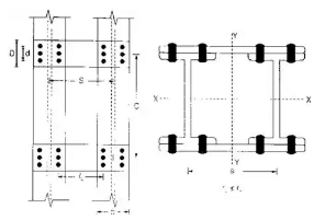

- The number of battens should be such that the member is divided into not less than three parts longitudinally.
2. Design Specifications:
- Spacing of battens C, from centre to centre of end fastening should be such that the slenderness ratio of the lesser main component,
 50 or 0.7 times the slenderness ratio of the compression member as a whole about x – y-axis (parallel to battens), which is less where C = spacing of battens as shown in fig.
 = minimum radius of gyration of components.
 - d > (3/4)a for immediate battens, d > a for end battens and d > 2 × b for any batten.
where d = effective depth of batten,
a = centroid distance of members,
b = width of member in the plane of batten. - Thickness of battens,
t > lb/50 where lb = distance between the innermost connecting line of rivets of welds.  and P = total axial load on the comp. member.
(i) Transverse shear V is divided equally between the parallel planes of battens. Battens and their connections to main components resist a longitudinal shear simultaneously.
V1 = V x C/N x S and a moment, M = V x C/2N where, C = spacing of battens
N = number of parallel planes of battens,
S = minimum transverse distance between centroids of rivet group or welding.
(ii) Check for longitudinal shear stress, where tva = permissible average shear stress= 100 MPa for steel of IS: 226-1975
D = overall depth of battens,
t = thickness of battens.
(iii) Check for bending stress, where, σbc σbt = permissible bending compressive or tensile) stress= 165 MPa for steel of IS: 226-1975
- End connections
(i) Design the end connections to resist the longitudinal shear force V1 and the moment M as calculated in step 4 above.(ii) For welded connections, Lap
 where t is the thickness of the plate
(iii) The total length of weld at the end of the edge of the batten

(iv) Length of weld at each edge of batten
 total length of weld required
(v) Return weld along the transverse axis of the column
 where t and D are the thickness and overall depth of the battens, respectively.
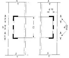
 t = thickness of batten
Slab Base
- Sufficient fastenings are provided to retain the column securely on the base plate and resist all moments and forces (except direct compression in the column.) arising during transit, unloading and erection.
- Area of slab base = axial load in the column/permissible compressive stress in concrete
- The thickness of a rectangular slab base as per IS 800: 1984.

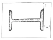 where t = the slab thickness (mm)
w = the pressure or loading on the underside of the base (MPa)
a = the greater projection of the plate beyond the column (mm) = max. (∝, β).
b = the lesser projection of the plate beyond the column (mm) = max. (∝, β).
σbs = the permissible bending stress in slab bases = 165 MPa for flanged beams
= MPa for solid beams. - The thickness of a square slab base plate under a solid round column.

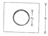 W = the total axial load (kN)
B = the length of the side of cap or base (mm)
d0 = the diameter of the reduced end (if any) of the column (mm).
The cap or base plate should not be less 1.5 (d0 +75) mm in length.
|
10 videos|24 docs|17 tests
|
FAQs on Compression Members - Design of Steel Structures - Civil Engineering (CE)
| 1. What are compression members in civil engineering? |  |
| 2. What are the types of compression members commonly used in civil engineering? |  |
| 3. What factors should be considered in the design of compression members? |  |
| 4. How are compression members designed to ensure their stability and safety? |  |
| 5. What are some common materials used for compression members in civil engineering? |  |


