Design of Beam

Design stress-strain curve at the ultimate state
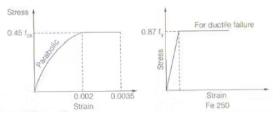
Design value of strength For concrete
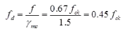
where, ymc = Partial factor of safety for concrete = 1.5
fd = design value of strength
For steel
fd = fy / 1.15 = 0.87fy
Singly Reinforced Beam
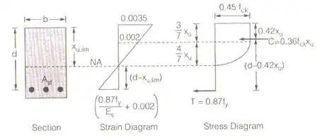
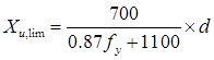
- Limiting depth of the neutral axis (xu, lim)
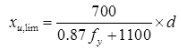
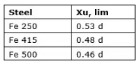
Here d = effective depth of the beam
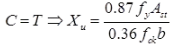
- Actual depth of neutral axis (Xu)
- Lever arm = d - 0.42 Xu
- Ultimate moment of resistance
Some special cases
- When Xu < Xu,lim
It is an under-reinforced section
Mu = 0.36 fckbXu(d - 0.42Xu)
or Mu = 0.87fyAst(d - 0.42Xu) - When Xu = Xu,lim
It is a balanced section
Mu = 0.36fckbXu,lim(d - 0.42Xu,lim)
or Mu = 0.87fyAst(d - 0.42Xu,lim) - When Xu > Xu,lim
It is over reinforced section. In this case, keep Xu limited to Xu,lim and moment of resistance of the section shall be limited to limiting moment of resistance, (Mu,lim)
Doubly Reinforced Section
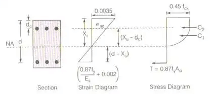
- Limiting depth of neutral axis.
- For actual depth of neutral axis (Xu)
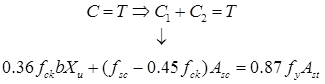
- Ultimate moment of resistance
Mu = 0.36fckbXu(d - 0.42Xu) + (fsc - 0.45fek)Asc(d - dc)
where fSC = stress in compression steel and it is calculated by strain at the location of compression steel (fSC)
T-Beam
- Effective width of flange Discussed in WSM
- Limiting depth of neutral axis
Singly reinforced T-Beam
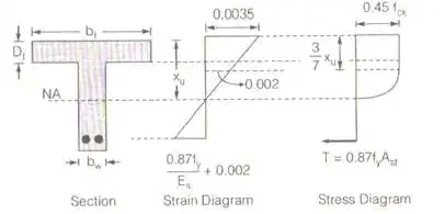
Case-1: When NA is in the flange area
i.e., Xu < Df
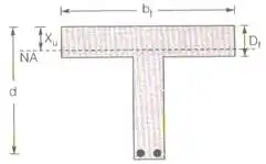
(i) for Xu
(ii) Ultimate moment of resistance
Mu = 0.36fckbfXu(d - 0.42Xu)
or Mu = 0.87 fyAst(d - 0.42Xu)
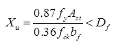
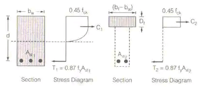
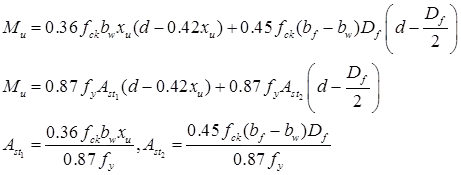
Case-2: When NA is in the web area (Xu > Df)
Case (a) when Xu > Df and 
i.e., depth of flange in less than the depth of the rectangular portion of the stress diagram.
- For actual depth of neutral, a is
0.36fekbwxu + 0.45fek(bf - bw)Df = 0.87fyAst - Ultimate moment of resistance
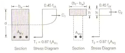
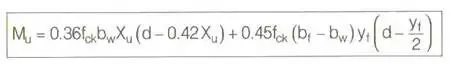
Special Case (2): When Xu > Df and 
i.e., the depth of the flange is more than the depth of the rectangular portion of the stress diagram.
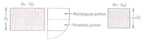
As per IS 456 : 2000
(bf - bw) Df portion of the flange is converted into (bf - bw)yf section for which stress is taken constantly throughout the section is 0.45 fck.
As per IS 456 : 2000
yf = 0.15Xu + 0.65Df < Df
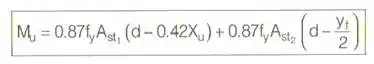
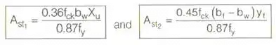
For actual depth of neutral axis
0.36fekbwXu + 0.45fek(bf - bw) yf = 0.87fyAst1 + 0.87fyAst2
or 0.36fckbwXu + 0.45fck(bf - bw)yf = 0.87fyAst
FAQs on Design of Beam
| 1. What is the purpose of beam design in civil engineering? |  |
| 2. What are the key factors considered in beam design? | |
| 3. What are the different types of beams used in civil engineering? | |
| 4. How is beam design affected by different load types? | |
| 5. What are the common methods used for beam design in civil engineering? | |


