Process Control Block (PCB) | Operating System - Computer Science Engineering (CSE) PDF Download
Overview
The process control block represents a process in the operating system. A process control block is also known as a task control block. It’s a repository of information associated with a specific process.
Scope
- We will learn about Process control block(PCB), its structure, role of PCB in operating systems.
- We will discuss each attribute of the process control block in detail.
- We will also learn about process tables and how PCBs are stored in memory.
- This article does not cover any process scheduling algorithm and code implementation.
Introduction
We come across many processes running at the same time in our operating system. Every process has some information and execution instructions accompanied. These instructions can be a code execution or a list of devices(like a printer) that will be used to interact, during the execution of a process. So, there arises a need for a data structure that can store every information of a process, known as a process control block (PCB).
Definition
When the process is created by the operating system it creates a data structure to store the information of that process. This is known as Process Control Block (PCB).
Process Control block (PCB) is a data structure that stores information of a process.
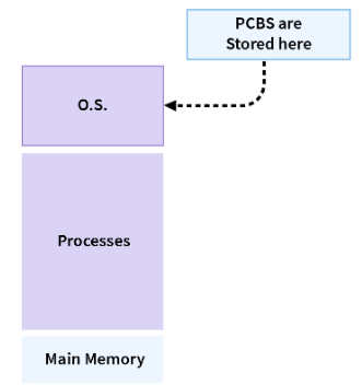
PCBs are stored in specially reserved memory for the operating system known as kernel space.
Note: The Random Access Memory (RAM) can be logically divided into two distinct regions namely - the kernel space and the user space. kernel space is the core of the operating system. It normally has full access to all memory and machine hardware and it cant be accessed by the user.
PCB is unique for every process which consists of various attributes such as process ID, priority, registers, program counters, process states, list of open files, etc.
Role of Process Control Block
It's the job of the operating system to assign a CPU to a process as the process doesn't need a CPU all the time. Let's take an example of the input/output process, they are only used by the CPU when triggered.
The role of the process control block arises as an identification card for each process. The Operating System doesn't know which process is which, until Operating System refers through the PCB of every process.
For Example:, there are MS word processes, pdf processes, printing processes, and many background processes are running currently on the CPU. How will OS identify and manage each process without knowing the identity of each process?
So, here PCB comes into play as a data structure to store information about each process.
Therefore, whenever a user triggers a process (like print command), a process control block (PCB) is created for that process in the operating system which is used by the operating system to execute and manage the processes when the operating system is free.
Structure of Process Control Block
The process control block contains many attributes such as process ID, process state, process priority, accounting information, program counter, CPU registers`, etc for each process.
Now we will discuss each field of PCB in detail.
1. Process ID:
When a new process is created by the user, the operating system assigns a unique ID i.e a process-ID to that process. This ID helps the process to be distinguished from other processes existing in the system.
The operating system has a limit on the maximum number of processes it is capable of dealing with, let's say OS can handle atmost N processes at a time.
So, process-ID will get the values from 0 to N-1.
- First process will be given ID0.
- Second process will be given ID 1.
- It continues till N-1.
Now if a new process is created after process(N-1) then Operating System will allot ID 0 to this new process considering the older process at id 0 is already terminated. This is one of the schemes for assigning the process ids.
There is another scheme of assignment where the process IDs are not allocated in ascending order.
Let's say a single PCB requires X bytes of memory and in total there can be N processes allowed at a time. Then, the operating system will reserve N*X bytes for all the PCBs.
These PCBs are numbered from 0 to N-1. Please note here we are giving IDs to PCBs and not to the processes.
Now whenever a process is triggered by the user a free PCB slot is allotted to that process and the process ID of that process will be the same as the PCB slot number. So, the operating system maintains a chain of free PCB slots. If the chain is empty no new process can be created.
2. Process State:
A process, from its creation to completion goes through different states. Generally, a process may be present in one of the 5 states during its execution:
- New: This state contains the processes which are ready to be loaded by the operating system into the main memory.
- Ready: This state contains the process which is both ready to be executed and is currently in the main memory of the system. The operating system brings the processes from secondary memory(hard disk) to main memory(RAM). As these processes are present in the main memory and are waiting to be assigned to the CPU, the state of these processes is known as Ready state.
- Running: This state contains the processes which are currently executed by the CPU in our system. If there is a total x CPU in our system, then a maximum number of running processes for a particular time is also x.
- Block or wait: A process from its running state may transition to a block or wait for state depending on the scheduling algorithm or because of the internal behavior of the process (process explicitly wants to wait).
- Termination: A process that completes its execution comes to its termination state. All the contents of that process(Process control block) will also be deleted by the operating system.
3. Process Priority:
Process priority is a numeric value that represents the priority of each process. The lesser the value, the greater the priority of that process. This priority is assigned at the time of the creation of the PCB and may depend on many factors like the age of that process, the resources consumed, and so on. The user can also externally assign a priority to the process.
4. Process Accounting Information:
This attribute gives the information of the resources used by that process in its lifetime. For Example: CPU time connection time, etc.
5. Program Counter:
The program counter is a pointer that points to the next instruction in the program to be executed. This attribute of PCB contains the address of the next instruction to be executed in the process.
6. CPU registers:
A CPU register is a quickly accessible small-sized location available to the CPU. These registers are stored in virtual memory(RAM).
7. Context Switching:
A context switching is a process that involves switching the CPU from one process or task to another. It is the process of storing the state of a process so that it can be restored and resume execution at a later point. This allows multiple processes to share a single CPU and is an essential feature of a multitasking operating system.
So, whenever context switching occurs in the code execution then the current state of that process is stored temporarily in CPU registers. This helps in the fast execution of the process by not wasting time-saving and retrieving state information from the secondary memory(hard disk).
8. PCB pointer:
This field contains the address of the next PCB, which is in ready state. This helps the operating system to hierarchically maintain an easy control flow between parent processes and child processes.
9. List of open files:
As the name suggests, It contains information on all the files that are used by that process. This field is important as it helps the operating system to close all the opened files at the termination state of the process.
10. Process I/O information:
In this field, the list of all the input/output devices which are required by that process during its execution is mentioned.
How PCBs are Stored?
PCBs are stored in the form of LinkedList in memory as shown in the figure.
Operating System uses Process Table to find the PCB present in memory.
Process table is a table that contains Process ID and the reference to the corresponding PCB in memory. We can visualize the Process table as a dictionary containing the list of all the processes running.
So, whenever a context switch occurs between processes the operating system refers to the Process table to find the reference to the PCB with the help of the corresponding Process ID.
Process Queues
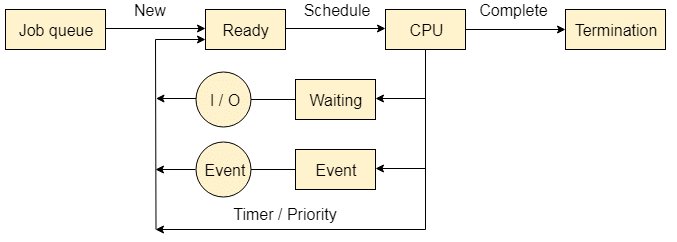
The Operating system manages various types of queues for each of the process states. The PCB related to the process is also stored in the queue of the same state. If the Process is moved from one state to another state then its PCB is also unlinked from the corresponding queue and added to the other state queue in which the transition is made.

There are the following queues maintained by the Operating system.
1. Job Queue
In starting, all the processes get stored in the job queue. It is maintained in the secondary memory. The long term scheduler (Job scheduler) picks some of the jobs and put them in the primary memory.
2. Ready Queue
Ready queue is maintained in primary memory. The short term scheduler picks the job from the ready queue and dispatch to the CPU for the execution.
3. Waiting Queue
When the process needs some IO operation in order to complete its execution, OS changes the state of the process from running to waiting. The context (PCB) associated with the process gets stored on the waiting queue which will be used by the Processor when the process finishes the IO.
|
10 videos|141 docs|33 tests
|


