Receivers | Communication System - Electronics and Communication Engineering (ECE) PDF Download
Introduction
This unit centres around basic principles of the superheterodyne receiver. In this article, we will discuss the reasons for the use of the superheterodyne and some topics of its design, such as the choice of intermediate frequency, RF stage, oscillator tracking, bandspread tuning and frequency synthesis. Most of the information is standard textbook material but put together as an introductory article, it can provide somewhere to start if you are contemplating building a receiver.
TRF Receiver
Early valve radio receivers were Tuned Radio Frequency (TRF) type consisting of one or a number of tuned radio frequency stages with individual tuned circuits which provided the selectivity to separate the received signal from others. The tuned circuits are segregated by the radio frequency (RF) amplifier stages and the last tuned circuit provided for the AM detector stage. This receiver was used before introduction of the screen grid valve and it is interesting to observe the grid-plate capacity neutralisation applied to the triode RF amplifiers to maintain amplifier stability. In these early receivers, the individual tuning capacitors were separatley attached to tuning dials, and each of these dials had to be reset each time a different station was selected. Designs evolved for receivers with only one adjustable dial, achieved by various methods of mechanical ganging the tuning capacitors, including the ganged multiple tuning capacitors with a common rotor shaft as used today.
The bandwidth of tuned circuit for the given Q is directly proportional to its operating frequency and hence, as higher and higher operating frequencies came into use, this is difficult to reach enough selectivity using the TRF Receiver system.

Tuned radio frequency (TRF) receiver
The Superheterodyne Principle:-
The Superheterodyne receiver was first evolved by Major Edwin Howard Armstrong, in 1918 and gradually phased out the TRF receiver during the 1930s.
- The principle of operation in the superheterodyne is illustrated by the diagram. In this system, the incoming signal is mixed with a local oscillator to produce sum and difference frequency components. The lower frequency difference component called the intermediate frequency (IF), is separated from the other components by fixed tuned amplifier stages set to the intermediate frequency. The tuning of the local oscillator is mechanically ganged to the tuning of the signal circuit or radio frequency (RF) stages so that the difference intermediate frequency is always the same fixed value. Detection takes place at intermediate frequency instead of a radio frequency as in the TRF receiver.

Superheterodyne Receiver
- Use of the fixed lower IF channel gives the following advantages:
- For a given Q factor in the tuned circuits, the bandwidth is lower making it easier to achieve the required selectivity.
- At lower frequencies, circuit losses are often lower allowing higher Q factors to be achieved and hence, even greater selectivity and higher gain in the tuned circuits.
- It is easier to control, or shape, the bandwidth characteristic at one fixed frequency. Filters can be easily designed with the desired bandpass characteristic and slope characteristic, an impossible task for circuits which tune over a range of frequencies.
- Since the receiver selectivity and most of the receiver pre-detection gain, are both controlled by the fixed IF stages, the selectivity and gain of the superheterodyne receiver are more consistent over its tuning range than in the TRF receiver.
- One problem, which has to have contended within the superheterodyne receiver, is its ability to pick up a second or imago frequency removed from the signal frequency by a value equal to twice the intermediate frequency.
Choice of intermediate frequency
- A number of further factors influence the choice of the intermediate frequency:
- The frequency should be free from radio interference. Standard intermediate frequencies have been established and these are kept dear of signal channel allocation. If possible, one of these standard frequencies should be used.
- An intermediate frequency which is close to some part of the tuning range of the receiver is avoided as this leads to instability when the receiver is tuned near the frequency of the IF channel.
- Ideally, low order harmonics of the intermediate frequency (particularly second and third order) should not fall within the tuning range of the receiver. This requirement cannot always be achieved resulting in possible heterodyne whistles at certain spots within the tuning range.
- Sometimes, quite a high intermediate frequency is chosen because the channel must pass very wideband signals such as those modulated by 5 MHz video used in television. In this case, the wide bandwidth circuits are difficult to achieve unless quite high frequencies are used.
- For reasons outlined previously, the intermediate frequency is normally lower than the RF or signal frequency. However, there we some applications, such as in tuning the Low Frequency (LF) band, where this situation could be reversed. In this case, there are difficulties in making the local oscillator track with the signal circuits. Some modern continuous coverage HF receivers make use of the Wadley Loop or a synthesised VFO to achieve a stable first oscillator source and these have a first intermediate frequency above the highest signal frequency.
Multiple Conversion Super Heterodyne Receiver
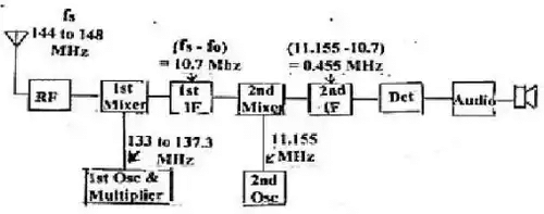
- In receivers tuning the upper HF and the VHF bands, two (or even more) IF channels are commonly used with two (or more) stages of frequency conversion. The lowest frequency IF channel provides the selectivity or bandwidth control that is needed and the highest frequency IF channel is used to achieve good Image rejection
- A typical system used in two meter FM amateur transceivers is shown in Figure. In this system, IF channels of 10.7 MHz and 455 kHz are used for a double conversion. The requirement Is different to that of the wideband FM broadcasting system as frequency deviation is only 5 kHz with an audio frequency spectrum limited to below 2.5 kHz. Channel spacing is 25 kHz and bandwidth is usually limited to less than 15 kHz so that the narrower bandwidth 455 kHz IF channel is suitable.

The RF Amplifier
A good receiver has at least one tuned RF amplifier stage ahead of the first mixer. As already discussed, one function of the RF stage is to reduce the image frequency level into the mixer. The RF stage also carries out a number of other useful functions:
- The noise figure of a receiver is essentially determined by the noise generated in the first stage connected to the aerial system. Mixer stages are inherently more noisy than straight amplifiers and a function of the RF amplifier is to raise the signal level into the mixer so that the signal to noise ratio is determined by the RF amplifier characteristics rather than those of the mixer.
- There is generally an optimum signal Input level for mixer stages. If the signal level is increased beyond this optimum point, the levels of intermodulation products steeply increase and these products can cause undesirable effects on the receiver performance. If the signal level is too low, the signal-to-noise rate will be poor. A function of the RF amplifier is to regulate the signal level into the mixer to maintain a more constant, near optimum, level. To achieve this regulation, the gain of the RF stage is controlled by an automatic gain control system, or a manual gain control system, or both.
- Because of its non-linear characteristic, the mixer is more prone to cross-modulation from a strong signal on a different frequency that is the RF amplifier. The RF tuned circuits, ahead of the mixer, help to reduce the level of the unwanted signal into the mixer input and hence reduce the susceptibility of the mixer to cross-modulation.
- If, by chance, a signal exists at or near the IF, the RF tuned circuits provide attenuation to that signal.
- The RF stage provides isolation to prevent signals from the local oscillator reaching the aerial and causing interference by being radiated.
Oscillator Tracking
- While the local oscillator circuit tunes over a change in frequency equal to that of the RF circuits, the actual frequency is normally higher to produce the IF frequency difference component and hence less tuning capacity change is needed than in the RF tuned circuits.
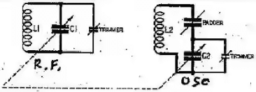
- Where a variable tuning gang capacitor has sections of the same capacitance range used for both RF and oscillator tuning, tracking of the oscillator and RF tuned circuits is achieved by capacitive trimming and padding.
- The figure shows a local oscillator tuned circuit (L2, C2) ganged to an RF tuned circuit (L1, C1) with C1 and C2 on a common rotor shaft. The values of inductance are set so that at the centre of the tuning range, the oscillator circuit tunes to a frequency equal to RF or signal frequency plus intermediate frequency.

- A capacitor called a padder, in series with the oscillator tuned circuit, reduces the maximum capacity in that tuning section so that the circuit tracks with the RF section near the low-frequency end of the band.
- Small trimming capacitors are connected across both the RF and oscillator tuned circuits to adjust the minimum tuning capacity and affect the high-frequency end of the band.
- The oscillator trimmer is preset with a little more capacity than the RF trimmer so that the oscillator circuit tracks with RF trimmer near the high-frequency end of the band.
Oscillator Stability
- The higher the input frequency of a receiver, the higher is the first local oscillator frequency and the greater is the need for oscillator stability. A given percentage frequency drift at higher frequencies amounts to a larger percentage drift in IF at the detector. Good stability is particularly important in a single sideband receiver as a small change in signal frequency is very noticeable as a change in the speech quality, more so that would be noticeable in AM or FM systems.
- One way to stabilize a receiver tunable oscillator is to use an automatic frequency control (AFC) system. To do this, a frequency discriminator can be operated from the last IF stage and its output fed back via a low-pass filter (or long time constant circuit) to a frequency sensitive element in the oscillator. Many of today's receivers and transceivers also make use of phase locked loop techniques to achieve frequency control.
- Where there are several stages of frequency conversion and the front end is tuned, the following oscillator stages, associated with later stage conversion, are usually fixed in frequency and can be made stable by quartz crystal control. In this case, receiver frequency stability is set by the first oscillator stability.
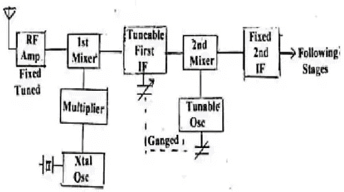
- One arrangement, which can give better stability, is to crystal lock the first oscillator stage but tune the first IF stage and second oscillator stage as shown in Figure. In this case, the RF tuned circuits are sufficiently broadband to cover a limited tuning range (such as an amateur band) but selective enough to attenuate the image frequency and other possible unwanted signals outside the tuning range.
- This is the method used when a converter Is added to the front end of an HF receiver to tune say the two-meter band.
- The RF circuits in the converter are fixed, the converter oscillator is crystal locked and the HF receiver RF and first oscillator circuits become the tunable first IF stage and second tunable oscillator, respectively. Since the HF receiver tunable oscillator is working at a lower frequency than the first oscillator in the converter, the whole system is inherently more stable than if the converter oscillator were tuned.

Some Important Terms
- Grid Valve: The control grid is an electrode used in amplifying thermionic valves (vacuum tubes) such as the triode, tetrode and pentode, used to control the flow of electrons from the cathode to the anode (plate) electrode.
- Radio Frequency: Radio frequencies are used in communication devices such as transmitters, receivers, computers, televisions, and mobile phones, to name a few. Radio frequencies are also applied in carrier current systems including telephony and control circuits.
- Intermediate Frequency: In communications and electronic engineering, an intermediate frequency (IF) is a frequency to which a carrier wave is shifted as an intermediate step in transmission or reception. When several stages of filters are used, they can all be set to a fixed frequency, which makes them easier to build and tune.
- RF signal range: Radio frequency (RF) is the oscillation rate of an alternating electric current or voltage or of a magnetic, electric or electromagnetic field or mechanical system in the frequency range from around 20 kHz to around 300 GHz.
|
14 videos|44 docs|30 tests
|


