Modulation Schemes & Decoding | Communication System - Electronics and Communication Engineering (ECE) PDF Download
Introduction
- The term digital communication covers a broad area of communications techniques, including digital transmission and digital radio.
- Digital transmission is the transmitted of digital pulses between two or more points in a communication system.
- Digital radio is the transmitted of digital modulated analog carriers between two or more points in a communication system.
- The primary advantage is the ease with which digital signals, compared to analog signal, are regenerative.
The shape of the waveform is affected by two mechanisms:
- As all the transmission lines and circuits have some non-ideal transfer function, there is a distorting effect on the ideal pulse.
- Unwanted electrical noise or other interference further distorts the pulse waveform.
Both of these mechanisms cause the pulse shape to degrade as a function of distance. During the time that the transmitted pulse can still be reliably identified, the pulse is thus regenerated. The circuit that perform this function at regular intervals along a transmission system are called regenerative repeaters.
- Digital circuits are less subject to distortion and interference than analog circuits.
- Digital circuits are more reliable and can be produced at lower cost than analog circuits. Also, digital hardware lends itself to more flexible implementation than analog hardware.
- Digital techniques lend themselves naturally to signal processing functions that protect against interference and jamming.
Elements of Digital Communication: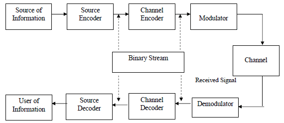
- The source output may be either an analog signal (such as an audio or video signal) or a digital signal (such as the output of a teletype machine) that is discrete in time and has a finite number of output characters.
- In a digital communication system, the messages produced by the source are converted into a sequence of binary digits. The process of efficiently converting the output of either an analog or digital source into a sequence of binary digits is called source encoding or data compression.
- The sequence of binary digits from the source encoder, which we call the information sequence, is passed to the channel encoder. The purpose of the channel encoder is to introduce, in a controlled manner, some redundancy in the binary information sequence that can be used at the receiver to overcome the effects of noise and interference encountered in the transmission of the signal through the channel. This increase the reliability of the received data and improves the fidelity of the received signal.
- The binary sequence at the output of the channel encoder is passed to the digital modulator, which serves as the interface to the communication channel. Since nearly all the communication channels encountered in practice are capable of transmitting electrical signals (waveforms), the primary purpose of the digital modulator is to map the binary information sequence into signal waveforms.
- Let us suppose that the coded information sequence is to be transmitted one bit at a time at some uniform rate R bits per second (bits/s). The digital modulator may simply map the binary digit 0 into a waveform so(t) and the binary digit 1 into a waveform s, (t). In this manner, each bit from the channel encoder is transmitted separately. We call this binary modulation.
- Alternatively, the modulator may transmit 6 coded information bits at a time by using M = 2h distinct waveforms so(t), i = 0, 1, ..., M - 1, one waveform for each of the 26 possible b-bit sequences. We call this M-ary modulation (M > 2).
- Note that a new b-bit sequence enters the modulator every b/R seconds. Hence, when the channel bit rate R is fixed, the amount of time available to transmit one of the M waveforms corresponding to a b-bit sequence is b times the time period in a system that uses binary modulation.
- At the receiving end of a digital communication system, the digital demodulator processes the channel-corrupted transmitted waveform and reduces the waveforms to a sequence of numbers that represent estimates of the transmitted data symbols (binary or M-ary).
- This sequence of numbers is passed to the channel decoder, which attempts to reconstruct the original information sequence from knowledge of the code used by the channel encoder and the redundancy contained in the received data.
The source decoder accepts the output sequence from the channel decoder and, from knowledge of the source encoding method used, attempts to reconstruct the original signal from the source.
Pulse Code Modulation (PCM)
- The simplest form of pulse digital modulation is called Pulse Code Modulations (PCM), wherein each analogue sample value is quantized into a discrete value for representation as a digital code word.
- In this modulation scheme, we first sampled the analog signal then quantize it to convert it into levels and then encode it and then send it in the form of digital codes.
- If there is n bit quantizer and sampling rate is f S' then bit rate will be Rb = n.fs bits/sec
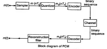
- The essential operations in the receiver are regeneration of impaired signals, decoding and demodulation of the train of quantized samples.
- Bandwidth requirement is minimum Rb /2 and maximum Rb.

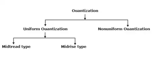
Quantization:
- Quantization refers to the use of a finite set of amplitude levels and the selections of a level nearest to a particular sample value of the message signal as the representation for it.
- Basically, the quantizers are of two types:
- Uniform quantizer
- Non-uniform quantizer.
Uniform Quantizer:
- A uniform quantizer is that type of quantizer in which the step size remains same throughout the input range.
- This is the process of setting the sample amplitude, which can be continuously variable to a discrete value.
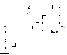
- We assume that the amplitude of the signal m(t) is confined to the range (-mp, +mp ). This range (2mp) is divided into L levels, each of step size δ = 2 mp / L.
- A sample amplitude value is approximated by the midpoint of the interval in which it lies.
- If we are using uniform quantizer with step size δ or Δ
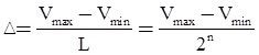
- Then maximum quantization error will be ± Δ /2
- Normally used uniform quantizers are mid tread type and midrise type.
 |
Test: Pulse Modulation
|
Start Test |
Non-uniform Quantizer:
- A non-uniform quantizer is that type of quantizer in which the step size varies according to the input values. Because of quantization, inherent errors are introduced in the signal. This error is called quantization error.
- Signal to quantization noise ratio for PCM for sinusoidal input is (for uniform quantizer)

where, n is bit of quantizer.
- As bit of quantizer increases SQNR increases but at the same time bandwidth requirement for transmission also increases.
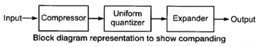
Companding Process :
To compress the signal at transmitter and expand the signal at receiver is combinely called as companding. Compression and expansion is done by passing the signal through the amplifier having non-linear transfer characteristics.
There are two types of companding techniques μ-law companding and A-law companding.
μ-law Companding:
- The compression characteristics is continuous.
- It uses a logarithmic compression curve which is ideal in the sense that quantization intervals and hence quantization noise is directly proportional to signal level
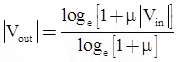
where, μmax = 225
A-law Companding:
- The compression characteristics is piecewise, made up of a linear segment for low level inputs and a logarithmic segment for high level inputs.
- This is the ITU-T standard.
- It is very similar to the μ-Law coding. It is represented by straight line segments to facilitate digital companding.
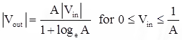

where, Amax = 87.6
- The signal to noise ratio of PCM remains almost constant with companding.
- Companding is done to avoid non-linear distortion of channel.
- Companding is widely used in telephone systems to reduce non-linear distortion and also to compensate for signal level difference between soft and loud talkers.
Differential Pulse Code Modulation (DPCM)
- Differential pulse-code modulation (DPCM) is a signal encoder that uses the baseline of pulse-code modulation (PCM) but adds some functionalities based on the prediction of the samples of the signal.
- The input can be an analog signal or a digital signal.
- If the input is a continuous-time analog signal, it needs to be sampled first so that a discrete-time signal is the input to the DPCM encoder.
- When the samples of a signal are highly correlated, then we go for DPCM in order to save bandwidth or using the same bandwidth at higher data rate.
- In DPCM, principle used is prediction.
The two main differential coding schemes are:
- Delta Modulation
- Differential PCM and Adaptive Differential PCM (ADPCM)
 |
Download the notes
Modulation Schemes & Decoding
|
Download as PDF |
Delta Modulation:
- Delta modulation converts an analogue signal, normally voice, into a digital signal.
- Delta modulation is a special case of differential pulse code modulation.
- It is called as one bit DPCM as it transmits only one bit per sample.
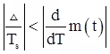
- In delta modulation, problem of slope overload occurs if input is changing very fast that is:
- To overcome slope overload error, we choose optimum size of Δ such that.
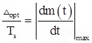
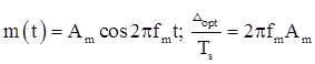
where, Δopt = Optimum size of Δ
Hunting is the second problem, this occur when message is almost constant.
Adaptive Delta Modulation:
The adaptive delta modulation is scheme in which, step choose step size in accordance with message signal’s sampled value to overcome slope overload error and hunting. If the message varies at a high rate, then step size is high and if message is varying slowely, then step size is small.
|
13 videos|39 docs|30 tests
|
FAQs on Modulation Schemes & Decoding - Communication System - Electronics and Communication Engineering (ECE)
| 1. What is Pulse Code Modulation (PCM)? |  |
| 2. What is the role of quantization in PCM? | |
| 3. What is the difference between uniform and non-uniform quantization? | |
| 4. What is companding in PCM? | |
| 5. What is the difference between μ-law and A-law companding? | |


Objective type Questions
,mock tests for examination
,Exam
,Semester Notes
,video lectures
,Sample Paper
,shortcuts and tricks
,Previous Year Questions with Solutions
,Free
,ppt
,Modulation Schemes & Decoding | Communication System - Electronics and Communication Engineering (ECE)
,practice quizzes
,Summary
,Modulation Schemes & Decoding | Communication System - Electronics and Communication Engineering (ECE)
,MCQs
,Modulation Schemes & Decoding | Communication System - Electronics and Communication Engineering (ECE)
,Viva Questions
,past year papers
,study material
,Extra Questions
,Important questions
;


Modulation Schemes & Decoding Free PDF Download
Importance of Modulation Schemes & Decoding
Modulation Schemes & Decoding Notes
Modulation Schemes & Decoding Electronics and Communication Engineering (ECE) Questions
Study Modulation Schemes & Decoding on the App
|
© EduRev
|
Education Revolution
|


|


