Measurement & Electrical Quantities | Electrical and Electronic Measurements - Electrical Engineering (EE) PDF Download

Electrical Instruments and Measurement
Instruments used to measure, current, voltage, power energy, flux, frequency etc., are called electrical measuring insturments.
Classification of Electrical Instrument
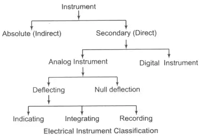
1. Absolute Instrument: It gives the value of the parameters under measurement in terms of the instrument.
e.g., Tangent galvanometer, Rayleigh's current balance.
2. Secondary Instrument: This instrument gives the value of parameters directly under measurement.
e.g., Voltmeter, thermometer, pressure gauge etc.
Note: Absolute instruments are highly accurate than secondary instrument as they contain less number of moving mechanical parts resulting in a lower operational of power consumption.
- Analog Instrument: Its output varies continuously with respect to time all the while maintaining a constant relationship with the input.
(i) Deflecting Instrument: This instrument gives the value of the parameters under measurement in terms of the deflection of the pointer away from the zero position. e.g., PMMC
(a) Indicating Instrument: This instrument gives the instantaneous value of the parameters under measurement. e.g., Ammeter, voltmeter, wattmeter, galvanometer.
(b) Integrating Instrument: It gives the sum total of the electrical parameter consumed over a specified period of time. e.g., Energy meter
(c) Recording Instrument: e.g., Recording voltmeter.
(ii) Null Deflection: Null deflecting type of instruments indicate their end of measurement with a zero deflection. e.g., Bridge circuit, DC potentiometer etc.
Note: Null deflecting instrument is highly accurate as the comparison to deflecting instrument as their operational power consumption at zero deflection is zero.
Key Points
- PMMC type instruments are used only in DC voltage and current.
- Induction type instruments are used only in AC (voltage and current) measurement.
- An electrodynamometer type instrument can be used to measure DC well as AC voltage.
Principle of Operation of Analog Instrument
- Electro Magnetic Effect Moving iron coil type, PMMC type, electro dynamometer type instrument.
- Induction Effect Energy meter
- Heating Effect Hot wire type, thermocouple, bolometer.
- Electrostatic Effect Electrostatic type of instrument.
- Hall’s Effect Fluxmeter, Poynting vector type wattmeter.
Essentials of Indicating Instrument
- Deflecting Torque/Force: Deflecting torque is proportional to quantity under measurement. The benefit of this torque is to deflect the pointer away from the zero position.
- Controlling Torque/Force (TC): It controls the deflection by bringing the pointer to rest at the steady state position.
It brings the pointer back to zero position when the parameter under measurement is removed.
Note: If control force is absent then the pointer will be deflected beyond maximum scale. - Damping Torque/Force (TD): This torque is damp out the oscillation of the pointer due to inertia.
- Construction Details of Indicating Instrument: Moving system of indicating instruments produces the deflecting torque. Various types of supports for moving system as :
Suspension
- Used in galvanometer class instrument.
- Used only in the vertically held instrument.
- Taut Suspension: It is used in PMMC type instrument require a low friction and high sensitivity.
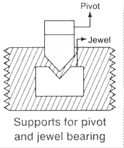
- Pivot and Jewel Bearing Type of Supports: Weight of moving system decides the sensitivity of the instrument directly.
 Note: Torque to weight ratio of the moving system should be high and equal to 0.1
 Note: Torque to weight ratio of the moving system should be high and equal to 0.1
Control System
There are two types of the mechanism is considered here. First one is spring control and the other one is gravity control mechanism as given below.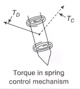
1. Spring Control Mechanism
Control torque TCS = kθ
where k = spring constant
θ = deflection
as Td ∞ l
at steady state position Td = Tc; θ ∞ l
Spring control has a uniform scale
Where, l = Length of strip
b = Width of strip
t = Thickness of strip
θ = Angle of deflection
E =Young’s modulus of the spring,
TCS = Control torque of spring torque mechanism.
Maximum fiber stress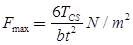
2. Gravity Control Mechanism
Tcg = K sin θ
Td ∞ l
at steady state position Td = Tcg
I ∞ sin θ
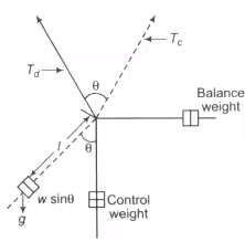 Gravity Control Mechanism
Where Td = Deflection torque
Tcg = Control torque of gravity control mechanism
Note: Gravity control mechanism has initially scale.
Key Points
- If damping torque Td is absent then pointer oscillate around the mean position.
- Fatigue in spring is avoided by annealing and aging.
Damping System
Damping system is provided in the instrument which helps the moving system of the instrument to reach to the final position at the earliest.
- Eddy Current Damping: Mechanism Used in a strong operating field. e.g., PMMC (Permanent Magnet Moving Coil instrument) type.
- Air Friction Damping: Used when the operating field is weak as used in moving iron and electro dynamometer type instrument.
- Fluid Friction Damping: Used in high voltage measurement. Used in the vertically mounted instrument. e.g., Electrostatic type instrument.
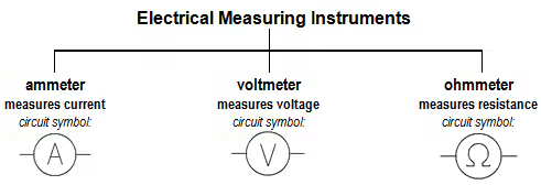
Measuring Current: Ammeters
For measurement of current, the circuit should be broken at the point where we want that current is to be measured, and the ammeter inserted at that point. An ammeter must be connected in series with the load under test.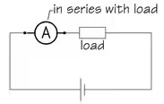
As it is important that the insertion of the ammeter into a network has small effect the circuit’s existing resistance and, thus alter the current normally flowing in the circuit, ammeters are manufactured with very small values of internal resistance.
Because ammeters have a very small internal resistance, it is vitally important that they are never connected in parallel with any circuit component —and particularly with the supply. It will result in a short-circuit current flowing through the instrument which may damage the ammeter.
Ammeters have a very low internal resistance, and must always be connected in series in a ciruit
Measuring Voltage: Voltmeters
To measure potential-difference or voltage, a voltmeter should be connected between two points at different potentials. So, a voltmeter must always be connected in parallel with the part of the network under test.
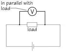
In order to operate, a voltmeter must, of course, draw some current from the circuit under test, and this can lead to inaccurate results because it can interfere with the normal condition of the circuit. We call this the ‘loading effect’ and, to minimise this ‘loading effect’ (and, therefore, improve the accuracy of a reading), this operating current must be as small as possible and, for this reason, voltmeters are manufactured with a very high value of internal resistance —usually many megohms.
Voltmeters must always be connected in parallel in a circuit, and have a very high internal resistance.
Types of Instruments used for Ammeter and Voltmeter
- PMMC (Permanent Magnet Moving Coil) Only for DC current measurement.
- Moving Iron Type For both AC and DC
- Electro Dynamometer Type For both AC and DC
- Electro Thermic Type For both AC and DC
Also for hot wire type, thermocouple type and bolometer. - Induction Type Only for AC measurement.
- Electrostatic Type Both AC and DC
- Rectifier Type Both AC and DC
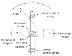
Permanent Magnet Moving Coil (PMMC) Type Instrument
It is used for measurement of DC only. Material used for magnet in PMMC is Alnico (AI + Ni + Co) and Alcomax (Al + Co + max….). The field strength in PMMC varies from 0.1 Wb/m2 to 1Wb/m2.
 Instrument for PMMC
- Concentric magnetic construction is used to get longer angular movement of the pointer.
- Due to the strong operating field of the permanent magnet, the eddy current damping mechanism is used to produce the damping torque.
- The control torque in PMMC is provided with spiral-shaped hair type phosphor-bronze spring.
Td = NBIA due to magnetic field
TC = Kθ due to control spring
At balance
As θ ∞ I
The scale of the PMMC instrument is uniform scale
where N = Number of turns of the moving coil
B = Flux density of permanent magnet in Wb/m2
A = Area of the coil in m2
I = Current in amp
G = NBA = Displacement constant of the galvanometer


Key Points
- The control spring in PMMC has dual utility, they not only produce controlling torque but also used to lead the current into the system.
- Due to strong operating torque at the permanent magnet, an eddy current damping is used to produce damping torque.
Advantages of PMMC
- High torque to weight ratio.
- High accuracy and sensitivity.
- Magnetic shielding not required due to a strong operating field.
- Low power consumption (25 – 200 μ W).
Disadvantages of PMMC
- High cost.
- Used for measurement of DC only.
- Limited current carrying capacity (100 mA) approx.
Sources of Errors
- Ageing effect of the permanent magnet (can be compensated by using a pre-edged magnet.
- Ageing effect of the spring.
- Temperature effect of the coil and the control spring.
Application of PMMC Instrument
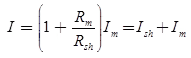
- Ammeter Shunt
Ish Rsh = ImRm
Shunt resistanceWhere, m = I/Im = Multiplying factor of the shuntBasic ammeter circuit
Rsh = Shunt resistance (Ω)
Rm = Internal resistance of the movement (Ω)
Im = Ifs = Full scale deflection current of the movement (A)
I = Full-scale current of the ammeter including the shunt. - Key Points
- Shunt should have a small and constant temperature coefficient.
- The materials used for the shunt in PMMC is Magnin as it gives small thermal emf with copper.
- Constanton is used for the construction of shunt in AC ammeter.

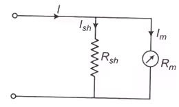
Effect of Temperature Change in Ammeter Reading
As temperature increases the resistance of copper increases and this result into a change of reading of the instrument. To reduce the effect of temperature a resistance having very small temperature coefficient made up of Magnin is connected in series with the coil and this is known as swamping resistance.
 Temperature's effect in ammeter reading
- Multi-Range Ammeters
The combination of a millivoltmeter and shunt employed as an ammeter is readily adaptable to multirange construction either by separate, in interchangeable, single-range shunts or multirange shunts. - By Using Separate Shunts
The circuits have three shunts which can be placed in parallel with the meter movement to give three different ranges I1, I2 and I3.Circuit for three shunt - By Using Universal or Ayrton Shunt
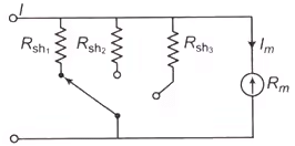
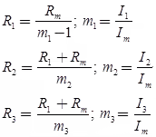
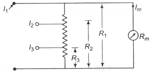
The universal shunt or ayrton shunt is shown in the figure is also used for multi-range ammeters. The advantage of this is that it eliminates the possibility of the meter being in the circuit without shunt.Aytron shunt circuit
 which can be placed in parallel with the meter movement to give three different ranges I1, I2 and I3.
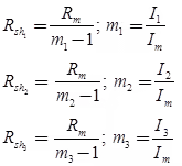
|
3 videos|39 docs|22 tests
|
FAQs on Measurement & Electrical Quantities - Electrical and Electronic Measurements - Electrical Engineering (EE)
| 1. What are electrical instruments used for in electrical engineering? |  |
| 2. What are some common types of electrical instruments used in measurement? | |
| 3. How does a voltmeter work in measuring voltage? | |
| 4. What is the significance of measuring electrical quantities in electrical engineering? | |
| 5. How does an ammeter work in measuring current? | |


video lectures
,shortcuts and tricks
,Summary
,Sample Paper
,Semester Notes
,Free
,MCQs
,Measurement & Electrical Quantities | Electrical and Electronic Measurements - Electrical Engineering (EE)
,Extra Questions
,Measurement & Electrical Quantities | Electrical and Electronic Measurements - Electrical Engineering (EE)
,past year papers
,study material
,Previous Year Questions with Solutions
,ppt
,practice quizzes
,Important questions
,Measurement & Electrical Quantities | Electrical and Electronic Measurements - Electrical Engineering (EE)
,Viva Questions
,mock tests for examination
,Exam
,Objective type Questions
;


Measurement & Electrical Quantities Free PDF Download
Importance of Measurement & Electrical Quantities
Measurement & Electrical Quantities Notes
Measurement & Electrical Quantities Electrical Engineering (EE) Questions
Study Measurement & Electrical Quantities on the App
|
© EduRev
|
Education Revolution
|


|


