
Best Study Material for Electrical Engineering (EE) Exam
Electrical Engineering (EE) Exam > Electrical Engineering (EE) Notes > GATE Notes & Videos for Electrical Engineering > Measurement of Power, Energy, and Power Factor
Measurement of Power, Energy, and Power Factor | GATE Notes & Videos for Electrical Engineering - Electrical Engineering (EE) PDF Download
Electric Power Measurements
1. DC Electric Circuits
In order to identify an electrical system in DC, a measurement of the electrical current, I, flowing through the bipoles and their electric voltage, V, across the terminals has to be formed.
These measurements can be arranged by means of a DC ammeter and voltmeter. The electric power, P, related to such a bipole, can be defined as the product of the voltage and current applied to: P =V × I . The power generated by an active bipole can
2. Single-Phase AC Electric Circuits
The electric power in a single-phase AC circuit can be defined as:
p(t) = v(t)i(t)
where p, v, i are instantaneous power, voltage, and current, respectively.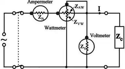 the instantaneous power is
p = v.i = 2 V I cos wt . cos (wt - φ)
The average power is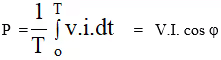
where V and I are the effective (R.M.S.) values of the voltage and current.
Voltage & Current Relationship in 3-Phase Circuit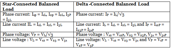
3. Three Phase Power Measurement using Two Watt-meter
Figure below shows the Two Watt-meter connection may be used to determine the power in a three-phase three-wire circuit (for unbalanced condition).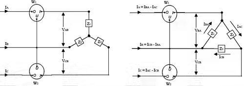 Star connection:
Power indicated by W1 :
P1 = VAB IA cosΦ
Power indicated by W2 :
P2 = VCB IC cosΦ
Power indicated by W2 :
P2 = VCB IC cosΦ
ΦCB-C is the phase difference between VCB and IC. VCB = VCN - VBN (Potential drop across W2).
Sum of the powers measured by the two wattmeters W1 and W2 would equal:
PT = P1 + P2
4. Three Phase Power Measurement – Analysis in the Balanced Case
Phase difference between VAB and VAN is 30°.
If the load is assumed to be inductive, the current is lagging behind their respective phase voltage by Φ, the phase difference between IA and VAB is = (30°+ Φ).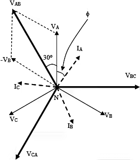
- For a balanced system the magnitudes VAB = VCB = VL (line voltage:voltage between any pair of terminals, eg. VAB).
For a balanced supply and three-phase load:
Power indicated by Watt-meter W1:
P1 = VabIa cosΦab-a = VL.IL.cos(Φ+30o)
where VL is the magnitude of the line voltage and IL that of the line current.
Power indicated by wattmeter W2:
P2 = VcbIc cosΦcb-c = VL.IL.cos(Φ - 30o)
The sum of the two Wattmeter readings:
P1 + P2 = VL.IL.cos(Φ +30o) + VL.IL.cos(Φ-30o) = VL.IL.[cos(Φ+30o) + cos(Φ-30o)]
= VL IL cosΦ
- This is the total power PT consumed by the load. Hence, the sum of the readings of the two meters gives the total power PT consumed by the load.
- In this method, the reading of the Wattmeter W1 can become negative if f is greater than 60o.
5. To Solve for Power Factor from the above analysis Consider P1 = W1 & P2 = W2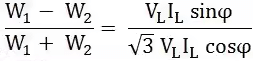
or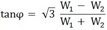
or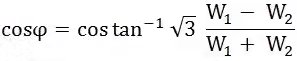
by using above formula we can easily calculate the condition of Power Factor.
Measurement of Power Factor
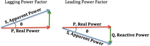
An AC system of Active power (P), Reactive power (Q), and Apparent power (S) plays a major role in electric power technology.
The terms of Active power, Reactive power, and Apparent power are applied to steady-state alternating current circuits in which the voltages and currents are non-sinusoidal.
Today it is characteristic in most parts of the applications that the current and voltage are Non-Sinusoidal.
1. Definition of Power Factor
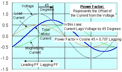 In the earlier definition the power factor is the classical definition, for pure sine wave current and voltage
- The power factor is basically the “angle cosine of that lagging current". In simple words, current is lagging by voltage with some angle and if we take the cosine of that angle we will get power factor.
- Now how to get that lagging angle? This is only problem left here. If somehow we can measure the time difference of both waveforms then we can find our required angle by using the formula below:
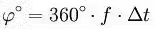
- Where frequency (f) is the frequency of the system which may be 50 or 60 Hz.
2. Zero Cross Detection
- Zero cross detection is a method which can enable us to measure the time between voltage and current.
- In this technique we get a high value whenever a zero will cross the system.
- There are many ways to implement it. But remember, this technique is the heart of this project so implementation must be accurate.
- In this project we implemented zero crossing using LM358 an 8 pin IC having dual amplifiers in it.
- In zero crossing, we have to get a “high” value during crossing of zero in waveforms. So to get that value we use amplifier as a comparator which will compare the non inverting reference value and then act accordingly.
3. Definition for non-sinusoidal current and sinusoidal voltage of power factor is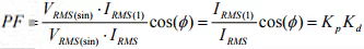
- The relationship between the Total Harmonic Distortion and Distortion Factor can be derived from the following expressions
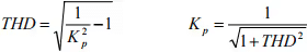
- The formula for the Power Factor by means of the Total Harmonic Distortion with zero phase shift between the voltage and the fundamental component of the current is given by
Measurement of Energy
Energy, heat, work and power are four concepts that are often confused. If force is exerted on an object and moves it over a distance, work is done, heat is released (under anything other than unrealistically ideal conditions) and energy is transformed. Energy, heat and work are three facets of the same concept. Energy is the capacity to do (and often the result of doing) work.
- The SI unit of energy, heat and work is the joule (J). The British thermal unit (Btu) or one of its multiples; and the kilowatt hour (kWh).
- Power is the rate at which work is done (or heat released, or energy converted).
- A light bulb draws 100 joules of energy per second of electricity, and uses that electricity to emit light and heat (both forms of energy). The rate of one joule per second is called a watt. The light bulb, operating at 100 J/s, is drawing power of 100 Watts.
1. Energy meter or watt hour meter is classified in accordance with several factors such as
- Type of display like analog or digital electric meter.
- Type of metering point like grid, secondary transmission, primary and local distribution.
- End applications like domestic, commercial and industrial.
- Technical like three phases, single phase, HT, LT and accuracy class meters.
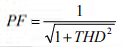
- It is the popularly known and most common type of age old watt hour meter.
- It consists of rotating aluminum disc mounted on a spindle between two electro magnets.
- Speed of rotation of disc is proportional to the power and this power is integrated by the use of counter mechanism and gear trains.
- It comprises of two silicon steel laminated electromagnets i.e., series and shunt magnets.
 |
Download the notes
Measurement of Power, Energy, and Power Factor
|
Download as PDF |
Download as PDF
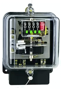
3. Electronic Energy Meters
- These are of accurate, high procession and reliable types of measuring instruments as compared to conventional mechanical meters.
- It consumes less power and starts measuring instantaneously when connected to load.
- These meters might be analog or digital.
- In analog meters, power is converted to proportional frequency or pulse rate and it is integrated by counters placed inside it.
- In digital electric meter power is directly measured by high end processor.
- The power is integrated by logic circuits to get the energy and also for testing and calibration purpose. It is then converted to frequency or pulse rate.
It is an advanced metering technology involving placing intelligent meters to read, process and feedback the data to customers. It measures energy consumption, remotely switches the supply to customers and remotely controls the maximum electricity consumption. Smart metering system uses the advanced metering infrastructure system technology for better performance.
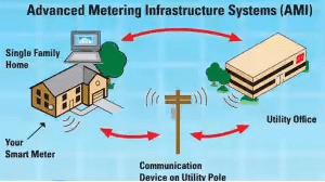
- These are capable of communicating in both directions.
- They can transmit the data to the utilities like energy consumption, parameter values, alarms, etc and also can receive information from utilities such as automatic meter reading system, reconnect/disconnect instructions, upgrading of meter software’s and other important messages.
5. Formula to calculate the amount of Energy consumed by a Load
The calculation is as follows:
[number of hours’ use] x [number of days’ use] x ([capacity of appliance expressed in watt] / 1,000) = number of kWh
The capacity should be divided by 1,000 to convert the number of watts into the number of kilowatts. This finally gives us the number of kWh (kilowatt-hours).
The document Measurement of Power, Energy, and Power Factor | GATE Notes & Videos for Electrical Engineering - Electrical Engineering (EE) is a part of the Electrical Engineering (EE) Course GATE Notes & Videos for Electrical Engineering.
All you need of Electrical Engineering (EE) at this link: Electrical Engineering (EE)
|
27 videos|329 docs
|


FAQs on Measurement of Power, Energy, and Power Factor - GATE Notes & Videos for Electrical Engineering - Electrical Engineering (EE)
| 1. What is power factor and why is it important in electrical power measurements? |  |
| 2. How is power factor measured in electrical power systems? | |
Ans. Power factor can be measured using a power factor meter or a power analyzer. These instruments measure the phase angle between the voltage and current waveforms in an electrical circuit to determine the power factor. Another method is to use a wattmeter to measure both the real power and the apparent power, and then calculate the power factor as the ratio of the two measurements.
| 3. What are the different methods for measuring electrical energy? | |
Ans. There are several methods for measuring electrical energy. The most common method is to use an energy meter, also known as a watt-hour meter. This device measures the cumulative energy consumption over a period of time by integrating the product of voltage and current. Another method is to use a digital energy meter, which measures and displays the energy consumption in real-time. Additionally, smart meters are becoming increasingly popular, as they provide advanced features such as remote monitoring and load management.
| 4. How can power factor correction be achieved in electrical systems? | |
Ans. Power factor correction can be achieved by installing power factor correction capacitors in parallel with the load. These capacitors supply reactive power to compensate for the reactive components in the load, thereby improving the power factor. Another method is to use active power factor correction techniques, which involve the use of power electronics to actively control the current waveform and improve the power factor. Power factor correction not only helps in reducing energy losses but also improves the overall efficiency of the electrical system.
| 5. What are the benefits of maintaining a high power factor in electrical systems? | |
Ans. Maintaining a high power factor in electrical systems offers several benefits. Firstly, it reduces the amount of reactive power flowing through the system, which results in lower energy losses. This leads to increased efficiency and reduced electricity bills. Secondly, a high power factor helps to increase the capacity of electrical equipment, allowing for more loads to be connected to the system without overloading it. Additionally, a high power factor improves the voltage stability and reduces voltage drops in the electrical system, ensuring reliable operation of electrical devices.
Related Exams
About this Document

4.88/5
Rating

Apr 14, 2025
Last updated
Document Description: Measurement of Power, Energy, and Power Factor for Electrical Engineering (EE) 2025 is part of GATE Notes & Videos for Electrical Engineering preparation.
The notes and questions for Measurement of Power, Energy, and Power Factor have been prepared according to the Electrical Engineering (EE) exam syllabus. Information about Measurement of Power, Energy, and Power Factor covers topics
like Electric Power Measurements, Measurement of Power Factor, Measurement of Energy and Measurement of Power, Energy, and Power Factor Example, for Electrical Engineering (EE) 2025 Exam. Find important definitions, questions, notes, meanings, examples, exercises and tests below for Measurement of Power, Energy, and Power Factor.
Introduction of Measurement of Power, Energy, and Power Factor in English is available as part of our GATE Notes & Videos for Electrical Engineering
for Electrical Engineering (EE) & Measurement of Power, Energy, and Power Factor in Hindi for GATE Notes & Videos for Electrical Engineering course.
Download more important topics related with notes, lectures and mock test series for Electrical Engineering (EE)
Exam by signing up for free. Electrical Engineering (EE): Measurement of Power, Energy, and Power Factor | GATE Notes & Videos for Electrical Engineering - Electrical Engineering (EE)
Description
Full syllabus notes, lecture & questions for Measurement of Power, Energy, and Power Factor | GATE Notes & Videos for Electrical Engineering - Electrical Engineering (EE) - Electrical Engineering (EE) | Plus excerises question with solution to help you revise complete syllabus for GATE Notes & Videos for Electrical Engineering | Best notes, free PDF download
Information about Measurement of Power, Energy, and Power Factor
In this doc you can find the meaning of Measurement of Power, Energy, and Power Factor defined & explained in the simplest way possible. Besides explaining types of
Measurement of Power, Energy, and Power Factor theory, EduRev gives you an ample number of questions to practice Measurement of Power, Energy, and Power Factor tests, examples and also practice Electrical Engineering (EE)
tests

Related Searches
shortcuts and tricks
,and Power Factor | GATE Notes & Videos for Electrical Engineering - Electrical Engineering (EE)
,Measurement of Power
,and Power Factor | GATE Notes & Videos for Electrical Engineering - Electrical Engineering (EE)
,Viva Questions
,Energy
,Measurement of Power
,practice quizzes
,and Power Factor | GATE Notes & Videos for Electrical Engineering - Electrical Engineering (EE)
,Important questions
,past year papers
,Objective type Questions
,Energy
,Sample Paper
,Previous Year Questions with Solutions
,video lectures
,Exam
,ppt
,study material
,Semester Notes
,Extra Questions
,Measurement of Power
,Free
,mock tests for examination
,Summary
,Energy
,MCQs
;


Additional Information about Measurement of Power, Energy, and Power Factor for Electrical Engineering (EE) Preparation
Measurement of Power, Energy, and Power Factor Free PDF Download
The Measurement of Power, Energy, and Power Factor is an invaluable resource that delves deep into the core of the Electrical Engineering (EE) exam.
These study notes are curated by experts and cover all the essential topics and concepts, making your preparation more efficient and effective.
With the help of these notes, you can grasp complex subjects quickly, revise important points easily,
and reinforce your understanding of key concepts. The study notes are presented in a concise and easy-to-understand manner,
allowing you to optimize your learning process. Whether you're looking for best-recommended books, sample papers, study material,
or toppers' notes, this PDF has got you covered. Download the Measurement of Power, Energy, and Power Factor now and kickstart your journey towards success in the Electrical Engineering (EE) exam.
Importance of Measurement of Power, Energy, and Power Factor
The importance of Measurement of Power, Energy, and Power Factor cannot be overstated, especially for Electrical Engineering (EE) aspirants.
This document holds the key to success in the Electrical Engineering (EE) exam.
It offers a detailed understanding of the concept, providing invaluable insights into the topic.
By knowing the concepts well in advance, students can plan their preparation effectively.
Utilize this indispensable guide for a well-rounded preparation and achieve your desired results.
Measurement of Power, Energy, and Power Factor Notes
Measurement of Power, Energy, and Power Factor Notes offer in-depth insights into the specific topic to help you master it with ease.
This comprehensive document covers all aspects related to Measurement of Power, Energy, and Power Factor.
It includes detailed information about the exam syllabus, recommended books, and study materials for a well-rounded preparation.
Practice papers and question papers enable you to assess your progress effectively.
Additionally, the paper analysis provides valuable tips for tackling the exam strategically.
Access to Toppers' notes gives you an edge in understanding complex concepts.
Whether you're a beginner or aiming for advanced proficiency, Measurement of Power, Energy, and Power Factor Notes on EduRev are your ultimate resource for success.
Measurement of Power, Energy, and Power Factor Electrical Engineering (EE) Questions
The "Measurement of Power, Energy, and Power Factor Electrical Engineering (EE) Questions" guide is a valuable resource for all aspiring students preparing for the
Electrical Engineering (EE) exam. It focuses on providing a wide range of practice questions to help students gauge
their understanding of the exam topics. These questions cover the entire syllabus, ensuring comprehensive preparation.
The guide includes previous years' question papers for students to familiarize themselves with the exam's format and difficulty level.
Additionally, it offers subject-specific question banks, allowing students to focus on weak areas and improve their performance.
Study Measurement of Power, Energy, and Power Factor on the App
Students of Electrical Engineering (EE) can study Measurement of Power, Energy, and Power Factor alongwith tests & analysis from the EduRev app,
which will help them while preparing for their exam. Apart from the Measurement of Power, Energy, and Power Factor,
students can also utilize the EduRev App for other study materials such as previous year question papers, syllabus, important questions, etc.
The EduRev App will make your learning easier as you can access it from anywhere you want.
The content of Measurement of Power, Energy, and Power Factor is prepared as per the latest Electrical Engineering (EE) syllabus.
|
© EduRev
|
Education Revolution
|


|


Signup to see your scores
go up within 7 days!
Access 1000+ FREE Docs, Videos and Tests
Takes less than 10 seconds to signup