Wave Optics

Refraction and Reflection of Plane Waves Using Huygens' Principle
As we know that when light falls on an object, it bends and move through the material, this is what refraction is. Also when the light bounces off the medium it is called a reflection.
Let us know study reflection and refraction of waves by Huygens' principle.
Reflection using Huygens Principle
- We can see a ray of light is incident on this surface and another ray which is parallel to this ray is also incident on this surface. Plane AB is incident at an angle ' i ' on the reflecting surface MN.
- As these rays are incident from the surface, so we call it incident ray. If we draw a perpendicular from point 'A' to this ray of light, Point A, and point B will have a line joining them and this is called as wavefront and this wavefront is incident on the surface.
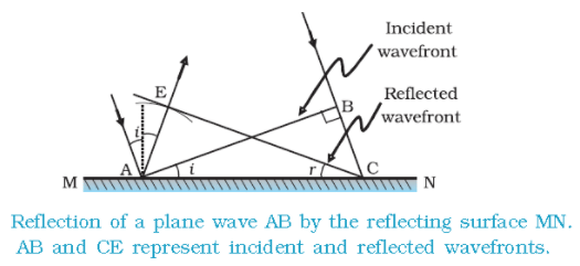
- These incident wavefront is carrying two points, point A and point B, so we can say that from point B to point C light is travelling a distance.
- If ' v ' represents the speed of the wave in the medium and if ' r ' represents the time taken by the wavefront from the point B to C then the distance, BC = v r.
- In order the construct the reflected wavefront we draw a sphere of radius v r from the point A. Let CE represent the tangent plane drawn from the point C to this sphere. So, AE = BC = v r
- If we now consider the triangles EAC and BAC, we will find that they are congruent and therefore, the angles ' i ' and 'r ' would be equal. This is the law of reflection.
Refraction using Huygens' principle
- We know that when a light travels from one transparent medium to another transparent medium its path changes.
- So the laws of refraction state that the angle of incidence is the angle between the incident ray and the normal and the angle of refraction is the angle between the refracted ray and the normal.
- The incident ray, reflected ray and the normal, to the interface of any two given mediums all lie in the same plane.
- We also know that the ratio of the sine of the angle of incidence and sine of the angle of refraction is constant.
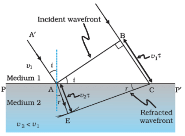 A plane wave AB is incident at an angle i on the surface PP' separating medium 1 and medium 2. The plane wave undergoes refraction and CE represents the refracted wavefront. the figure corresponds to v2 < v1 so that the refracted waves bends towards the normal.
- We can see a ray of light is incident on this surface and another ray which is parallel to this ray is also incident on this surface. As these rays are incident from the surface, so we call it incident ray.
Let PP' represent the medium 1 and medium 2. - The speed of the light in this medium is represented by v1 and v2. If we draw a perpendicular from point 'A' to this ray of light, Point A, and point B will have a line joining them and this is called as wavefront and this wavefront is incident on the surface.
- If ' r ' represents the time taken by the wavefront from the point B to C then the distance, BC = v1r, So to determine the shape of the refracted wavefront, we draw a sphere of radius v2r from the point A in the second medium.
- Let CE represent a tangent plane drawn from the point C on to the sphere. Then, AE = v2r, and CE would represent the refracted wavefront. If we now consider the triangles ABC and AEC, we readily obtain
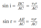
where' i ' and ' r ' are the angles of incidence and refraction, respectively. Substituting the values of v1 and v2 in terms of we get the Snell's Law, n1 sin i = n2 sin r
Behavior of Prism, Lens, and Spherical Mirror Towards Plane Wavefront
- Behavior of a Prism
Since light waves travel more slowly in glass, the lower part of the incoming wavefront, which passes through the greatest thickness of the prism, experiences the most delay. This delay causes a tilt in the emerging wavefront.
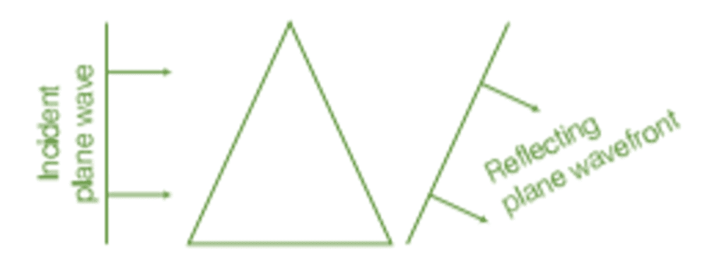 Reflection of plane wave by a thin prism
- Behavior of a Lens
The central portion of an incident plane wavefront passes through the thickest part of the lens and is delayed the most. As a result, the emerging wavefront becomes curved, forming a spherical shape that converges to a point F, known as the focus.
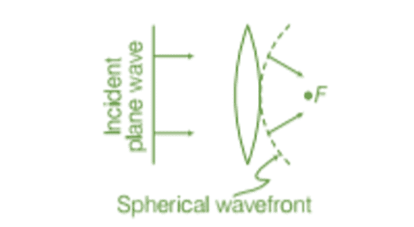 Reflection of plane wave by convex lens
- Behavior of a Spherical Mirror
The central part of the incoming wavefront travels the farthest distance before reflecting from the concave mirror. This extra distance causes a delay, resulting in the reflected wavefront being spherical and converging at the focal point F.
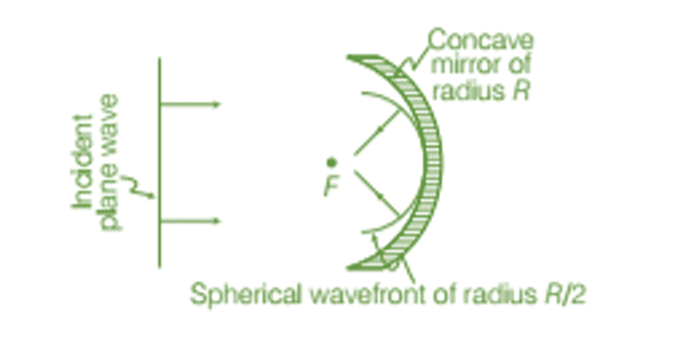 Reflection of plane wave by concave mirror
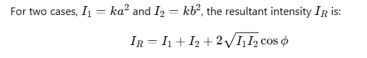
Theory of Interference of Waves
Superposition of Two Waves and Resultant Intensity
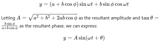
Let the waves from two sources be represented as:

where a and b are the amplitudes of the waves, and ϕ is the phase angle by which the second wave leads the first.
Using the principle of superposition, the total displacement y is:

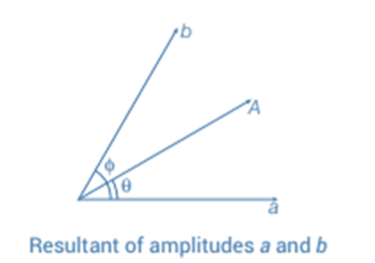
Applying trigonometric identities, we get:
Intensity of Resultant Wave
Since intensity I is proportional to the square of amplitude A, we have:

Conditions for Constructive and Destructive Interference
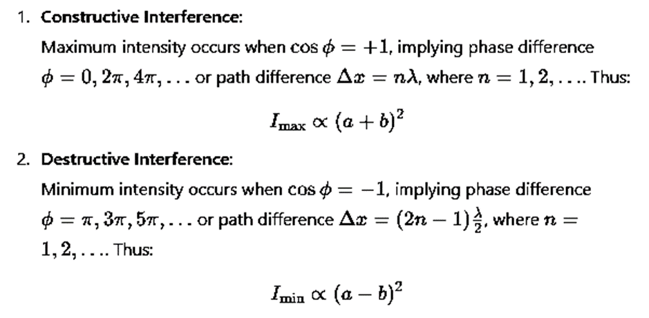
In summary, constructive interference occurs when the phase difference is an even multiple of π, and destructive interference occurs when it is an odd multiple of π, or equivalently, when the path difference is an integral multiple of λ or half-integral multiples of λ.
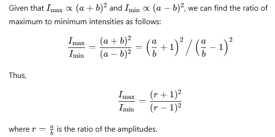
Comparison of Intensities of Maxima and Minima
Interference and Energy Conservation
In an interference pattern:
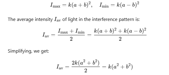
This shows that the light intensity is merely redistributed in the interference process, meaning energy is transferred from regions of destructive interference to regions of constructive interference. Therefore, the principle of energy conservation is maintained in light interference.
Try yourself: Which condition leads to constructive interference in the superposition of two waves?
Coherent and Incoherent Addition of waves
- Suppose there is a surface of the water and you take a needle and touch the surface of the water. What will happen? Yes, ripples are formed.
- Now if you take two needles and you touch the surface of the water with the needles. What do you think will happen?
- You will see a pattern. That pattern is the interference pattern.
- When you touch both the needles at the surface of the water at the same time, both the needles are in the same phase.
- Needle 1 will produce a wave. Also, needle 2 will produce its own ripples and they will intersect with waves of the first needle.
- Now, if both the needles are moving with the same velocity, the wave formed here are coherent.
- If the velocity of a 1st needle and 2nd needle are not steady they won't intersect. This is because one is at a steady speed and the other is at variable speed.
Coherent Waves
If the potential difference between two waves is zero or is constant w.r.t time, then the two ways are said to be coherent.
Non-coherent Waves

The waves are non-coherent if the potential difference between the two ways keeps on changing. Lightbulb, study lamp are the examples of the coherent waves. They emit waves at random potential difference.
Explanation
Now let us consider there are two needles say S1 and S2 moving up and down on the surface of the water and are pointing at point P. So the path difference here is given as S1P - S2P. Now the displacement by two needles and S1 S2 are:
y1 = A cos wt .................. (1)
y2 = A cos wt ................. (2)
So the resultant displacement at point P is, y = y1 + y2. When we substitute the value of y1 and y2 we write,
y = A cos wt + A cos wt
y = 2A cos wt.................... (3)
Now, we know the intensity is proportional to the square of the amplitude waves.
I0 ∝ A²
Where I0 is the initial intensity and A² is the amplitude of the wave. From equation 3, we say that A = 2A. So,
I0 ∝ (2A)² or I0 ∝ 4 A²
I = 4 I0
Now, if two needles that are S1 are S2 are in the same phase, the potential difference is,
S1P - S2P = nλ
Where n = 0, 1, 2,3 ......... and λ = the wavelength of the wave. If the two needles S1 and S2 are vibrating at its destructive interference then, the potential difference is
S1P - S2P = (n + 1/2) λ
Now if the potential difference of the waves is Φ then,
y1 = α cos wt
y2 = α cos wt
The individual intensity of each wave is I0 , we get,
y = y1 + y2
= α cos wt + α cos (wt +Φ)
y = 2 α cos(Φ/2) cos (wt + Φ/2)
Since, the intensity is I0 ∝ A²
I0 ∝ 4α² cos² (Φ/2)
I = 4 I0 cos² (Φ/2)
Well, the time-averaged value of cos²(Φt/2) is 1/2. So, the resultant intensity will be I = 2 I0 at all the points.
Conditions for Interference
Observable interference can take place if the following conditions are fulfilled:
(a) The two sources should emit, continuously, waves of some wave-length or frequency. While deriving conditions for maxima and minima, we have taken 'I' for both the waves to be same.
(b) The amplitudes of the two waves should be either or nearly equal. A good contrast between a maxima and minima can only be obtained if the amplitudes of two waves are equal or nearly equal.
(c) The two sources should be narrow. A broader source can be supposed to be a combination of a number of narrow sources assembled side-by-side. Interference patterns due to these narrow sources may overlap each other.
(d) The sources should be close to each other. The fringe width varies inversely as distance 'd' between the two sources. So, interference pattern will be more clear and distant if 'd' is small.

Interference Of Light Waves And Young's Experiment
The phenomenon of interference was first observed and demonstrated by Thomas Young in 1801. The experimental set up is shown in figure.
- Light from a narrow slit S, illuminated by a monochromatic source, is allowed to fall on two narrow slits A and B placed very close to each other.
- The width of each slit is about 0.03 mm and they are about 0.3 mm apart. Since A and B are equidistant from S, light waves from S reach A and B in phase. So A and B acts as coherent sources.
- According to Huygen's principle, wavelets from A and B spread out and overlapping takes place to the right side of AB. When a screen XY is placed at a distance of about 1 meter from the slits, equally spaced alternate bright and dark fringes appear on the screen.
- These are called interference fringes or bands.
- Using an eyepiece the fringes can be seen directly. At P on the screen, waves from A and B travel equal distances and arrive in phase. These two waves constructively interfere and bright fringe is observed at P.
- This is called central bright fringe.
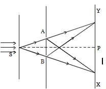
- When one of the slits is covered, the fringes disappear and there is uniform illumination on the screen. This shows clearly that the bands are due to interference.
- Let d be the distance between two coherent sources A and B of wavelength λ. A screen XY is placed parallel to AB at a distance D from the coherent sources. C is the midpoint of AB. O is a point on the screen equidistant from A and B. P is a point at a distance x from O, as shown in Fig 5.17.
- Waves from A and B meet at P in phase or out of phase depending upon the path difference between two waves. Draw AM perpendicular to BP.
- The path difference δ = BP - AP
δ = BP - AP = BP - MP = BM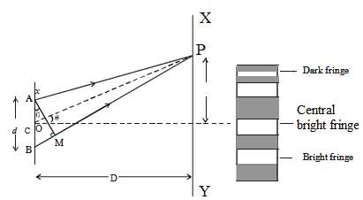
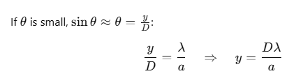
In right angled triangle ABM, BM = d sin θ, If θ is small, sin θ = θ
The path difference δ = θ.d
In right angled triangle COP, tan θ = OP/CO = x/D
For small values of θ, tan θ = θ
Thus, the path difference δ = xd/D
Bright Fringes
By the principle of interference, condition for constructive interference is the path difference = nλ
xd/D = nλ
Here, n = 0,1,2.....indicate the order of bright fringes
So, x = (D/d) nλ
This equation gives the distance of the nth bright fringe from the point O.
Dark Fringes
By the principle of interference, condition for destructive interference is the path difference = (2n-1)λ/2

Here, n = 1,2,3 ... indicate the order of the dark fringes.
So, x = (D/d) [(2n - 1)λ/2]
This equation gives the distance of the nth dark fringe from the point O. Thus, on the screen alternate dark and bright bands are seen on either side of the central bright band.
Band Width (β)
The distance between any two consecutive bright or dark bands is called bandwidth.
The distance between (n+1)th and nth order consecutive bright fringes from O is given by,
xn+1 - xn = [(D/d) [(n+1)λ] - (D/d) [(n)λ]] = (D/d) λBandwidth, β = (D/d) λ
Similarly, it can be proved that the distance between two consecutive dark bands is also equal to (D/d) λ. Since bright and dark fringes are of same width, they are equi-spaced on either side of central maximum.
Fringe Width
The distance between two consecutive bright or dark fringes in an interference pattern is called the fringe width W. It is given by:
This formula does not depend on n, meaning the width of all fringes is the same. Fringe width is directly proportional to the wavelength λ, so red light (with a longer wavelength) produces broader fringes than blue light (which has a shorter wavelength).
Intensity of the Fringes
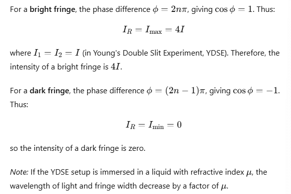
Distribution of Intensity
In Young's double slit experiment, the intensity distribution shows bright and dark fringes alternating with a maximum intensity of 4I at the bright fringes. The intensity pattern depends on path difference and phase difference between the waves from the two slits.
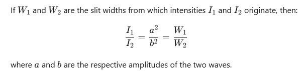
Relation among Intensity, Amplitude, and Width of the Slit
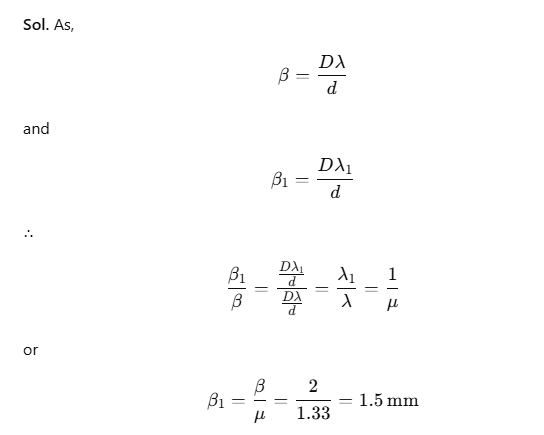
Example 1. In Young's experiment, the width of the fringes obtained with light of wavelength 6000 Å is 2 mm. What will be the fringe width, if the entire apparatus is immersed in a liquid of refractive index 1.33?
Conditions for Sustained Interference
To observe a clear interference pattern, it is essential that the intensity at constructive interference points is maximized, while at destructive interference points, it is nearly zero.
The following conditions must be met:
Coherence: The two sources creating the interference pattern must be coherent, meaning they should maintain a constant phase difference.
Same Polarization: The waves from both sources should have the same plane of polarization.
Proximity and Distance: The two sources should be very close to each other, and the observation should be made from a sufficient distance to obtain a noticeable fringe width, given by

Monochromatic Light: The sources must emit monochromatic light; otherwise, fringes of different colors will overlap and blur the pattern.
Equal Amplitudes: The waves should have equal amplitudes to provide a higher contrast between bright and dark fringes.
Did You Know?
- The dark and light regions are called interference fringes, the constructive and destructive interference of light waves.
- Interference fringes consisting of alternately bright and dark fringes (or bands) which are equally spaced are observed
- The distance D (from the double slits to the screen) is very much greater than d, typically ~ 1 m.
- The fringe separation Δx is increased if distance to the screen D is increased.
- The fringe separation Δx is decreased if slit separation a is increased.
- The fringe separation Δx is increased as wavelength of light λ is increased.
- The weave characteristics of light cause the light to pass through the slits and interfere with each other, producing the light and dark areas on the wall behind the slits. The light that appears on the wall behind the slits is partially absorbed by the wall, a characteristic of a particle.
- Constructive interference occurs when waves interfere with each other crest-to-crest and the waves are exactly in phase with each other. Destructive interference occurs when waves interfere with each other crest-to-trough (peak-to-valley) and are exactly out of phase with each other.
- Each point on the wall has a different distance to each slit; a different number of wavelengths fit in those two paths. If the two path lengths differ by a half a wavelength, the waves will interfere destructively. If the path length differs by a whole wavelength the waves interfere constructively.
Fringe Shift
In Young's double slit experiment, if a refracting slab of thickness t is placed in front of one of the slits, the interference fringe pattern shifts by n fringes, given by:
where μ is the refractive index of the slab.
If both slits are covered by refracting surfaces of thicknesses t1 and t2 with refractive indices μ1 and μ2, respectively, the fringe shift n is given by:
Diffraction of Light
Diffraction is the bending of light around sharp edges and the spreading of light within the geometric shadow of opaque obstacles. This bending causes light to deviate from a straight path. The effect is more pronounced when the size of the aperture or obstacle is comparable to the wavelength of light.
Note: Diffraction is common for all types of waves. However, since the wavelength of visible light is very small (10-6m), diffraction in visible light is rare because obstacles/apertures of such small sizes are uncommon.
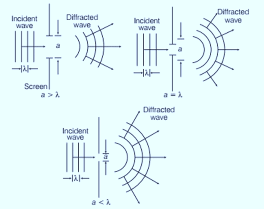 Diffraction of waves for slits of different width
Fresnel's Explanation: According to Fresnel, diffraction occurs due to the interference of secondary wavelets originating from parts of the wavefront that are not blocked by the obstacle or pass through the aperture.
Diffraction of Light at a Single Slit
When a parallel beam of light with a plane wavefront passes through a single slit of width a (comparable to the wavelength of light), diffraction occurs. The wavelets from the wavefront interfere constructively at the center, creating a central bright fringe. The diffraction pattern consists of a central bright band with alternating dark and weak bright bands of decreasing intensity on either side.
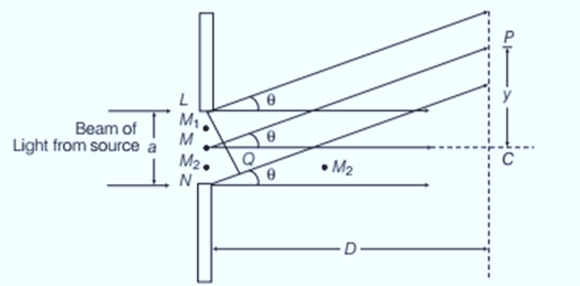 Geometry of single slit diffraction
To determine the conditions for secondary minima and maxima:
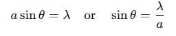
Secondary Minima:
The slit can be divided into even parts (2, 4, 6, ...) where the wavelets interfere destructively. For the n-th secondary minimum: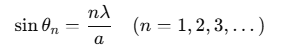
Secondary Maxima:
The slit can be divided into odd parts (3, 5, 7, ...), allowing constructive interference from alternate regions. For the n-th secondary maximum: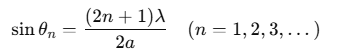
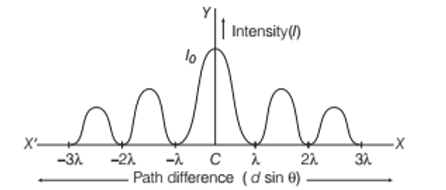 The central point C corresponds to the central maximum, with secondary minima at positions like ±λ, ±2λ, etc., and secondary maxima between these minima. This diffraction pattern is graphically represented with a central peak and decreasing side peaks. The conditions for diffraction maxima and minima are opposite to those for interference maxima and minima.
Width of Central Maximum
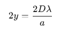
The width of the central maximum is defined as the distance between the first secondary minima on either side of the central bright fringe C.
For the first secondary minimum:
Thus, the width of the central maximum is:
As the slit width a increases, the width of the central maximum decreases.
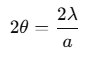
The angular width of the central maximum is given by:
Problem (JEE Advanced):
In Young's double slit experiment, the intensities at two points P1 and P2 on the screen are respectively I1 and I2. If P1 is located at the centre of a bright fringe and P2 is located at a distance equal to a quarter of fringe width from P1, then find I1/I2.
Solution:
Here, y = ω = λD/4d
x = yd/D = λ/4
φ = (2π/λ)x = π/2
φ/2 = π/4
Now, I2 = I1 cos2(φ/2)
Or, I1/ I2 = 1/cos2(φ/2) = 2
From the above observation we conclude that, the ratio of I1/I2 would be 2.
Problem:
A beam of light consisting of two wavelengths 6500 oA and 5200 oA is used to obtain interference fringes. The distance between the slits is 2.0 mm and the distance between the plane of the slits and the screen is 120 cm.
(a) Find the distance of the third bright fringe on the screen from the central maxima for the wavelength 6500 oA.
(b) What is the least distance from the central maxima where the bright fringes due to both the wavelengths coincide?
Solution:
(i) y3 = n. Dλ/d = 3 x 1.2m x 6500 x 10-10m / 2 x 10⁻³m = 0.12cm
Let nth maxima of light with wavelength 6500 Å coincides with that of mth maxima of 5200Å.
(ii) m x 6500Ao x D/d = n x 5200Ao x D/d ⇒ m/n = 5200/6500 = 4/5
Least distance = y4 = 4.D (6500Ao)/d = 4 x 6500 x 10-10 x 1.2/ 2 x 10⁻³m = 0.16cm
Test Your knowledge:
Q1. In Young's experiment be performed with two slits in water instead of in air:
(a) The fringes will be smaller in number
(b) The fringes will be broader
(c) The fringes will be narrower
(d) No fringes will be obtained
Sol. (a) The fringes will be smaller in number
Q2. In Young's interference experiment with one source and two slits, one slit is covered with a cello phone sheet so that half the intensity is absorbed. Then:
(a) No fringe is obtained
(b) Bright fringe will be brighter and dark fringe is darker
(c) All fringes will be darker
(d) Bright fringes will be less bright and dark fringes will be less dark.
Sol. (c) All fringes will be darker
Q3. In Young's interference experiment, the separation between the slits is halved and the distance between slits and the screen is doubled. The fringe width is:
(a) Unchanged (b) Halved
(c) Doubled (d) Quadruple
Sol. (d) Quadruple
Q4. In Young's experiment for interference of light with two slits, reinforcement takes place when sinθ = mλ/d, d is,
(a) distance from slit to screen
(b) distance between dark and bright fringe
(c) distance between the slits
(d) width of mth fringe.
Sol. (c) distance between the slits
Q5. In Young's double slit experiment, the distance between the slits is gradually increased. the width of the fringes system:
(a) increases
(b) decreases
(c) remains the same
(d) halved
Sol. (a) increases
FAQs on Wave Optics
| 1. What is Huygens' Principle and how does it explain the refraction and reflection of plane waves? |  |
| 2. What is the theory of interference of waves? | |
| 3. What is the difference between coherent and incoherent addition of waves? | |
| 4. How does Young's Experiment demonstrate interference of light waves? | |
| 5. What is diffraction of light and how does it relate to wave optics? | |


