Steady-State Errors | Control Systems - Electrical Engineering (EE) PDF Download
Introduction
The deviation of the output of control system from desired response during steady state is known as steady state error. It is represented as ess. We can find steady state error using the final value theorem as follows. Where,
E(s) is the Laplace transform of the error signal, e(t)
Let us discuss how to find steady state errors for unity feedback and non-unity feedback control systems one by one.
Steady State Errors for Unity Feedback Systems
Consider the following block diagram of closed loop control system, which is having unity negative feedback.
Where,
- R(s) is the Laplace transform of the reference Input signal r(t)
- C(s) is the Laplace transform of the output signal c(t)
We know the transfer function of the unity negative feedback closed loop control system as

The output of the summing point is -
E(s)=R(s)−C(s)
Substitute C(s) value in the above equation.


Substitute E(s) value in the steady state error formula
The following table shows the steady state errors and the error constants for standard input signals like unit step, unit ramp & unit parabolic signals.
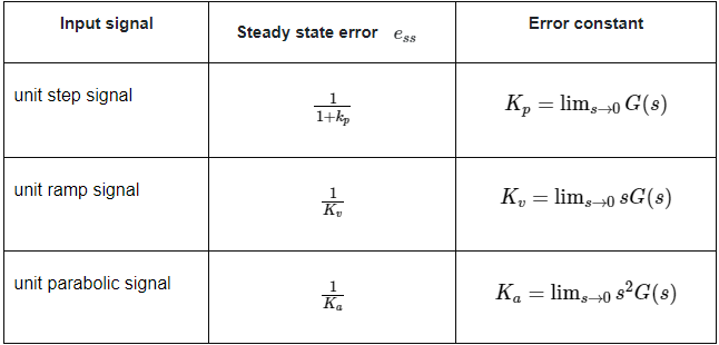
Where, Kp, Kv and Ka are position error constant, velocity error constant and acceleration error constant respectively.
Note
- If any of the above input signals has the amplitude other than unity, then multiply corresponding steady state error with that amplitude.
- We can’t define the steady state error for the unit impulse signal because, it exists only at origin. So, we can’t compare the impulse response with the unit impulse input as t denotes infinity.
Example
Let us find the steady state error for an input signal  of unity negative feedback control system with
The given input signal is a combination of three signals step, ramp and parabolic. The following table shows the error constants and steady state error values for these three signals.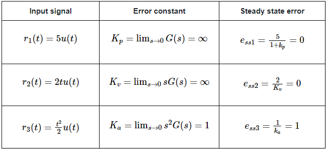 We will get the overall steady state error, by adding the above three steady state errors.
Therefore, we got the steady state error ess as 1 for this example.
Steady State Errors for Non-Unity Feedback Systems
Consider the following block diagram of closed loop control system, which is having nonunity negative feedback.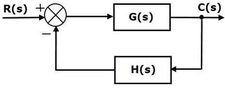 We can find the steady state errors only for the unity feedback systems. So, we have to convert the non-unity feedback system into unity feedback system. For this, include one unity positive feedback path and one unity negative feedback path in the above block diagram. The new block diagram looks like as shown below.
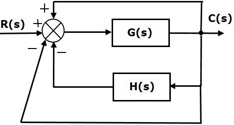 Simplify the above block diagram by keeping the unity negative feedback as it is. The following is the simplified block diagram.
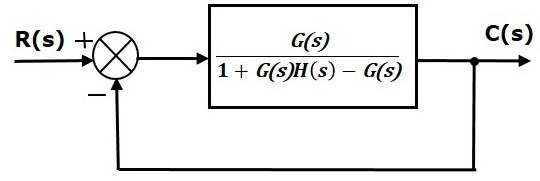 This block diagram resembles the block diagram of the unity negative feedback closed loop control system. Here, the single block is having the transfer function
instead of G(s). You can now calculate the steady state errors by using steady state error formula given for the unity negative feedback systems.
Note: It is meaningless to find the steady state errors for unstable closed loop systems. So, we have to calculate the steady state errors only for closed loop stable systems. This means we need to check whether the control system is stable or not before finding the steady state errors. In the next chapter, we will discuss the concepts-related stability.
|
53 videos|107 docs|40 tests
|


