Electrical Engineering (EE) Exam > Electrical Engineering (EE) Notes > Control Systems > Short Notes: Lag Compensator
Short Notes: Lag Compensator | Control Systems - Electrical Engineering (EE) PDF Download

Introduction
- A lag compensator is a circuit that is designed to generate a steady-state sinusoidal signal having a phase lag to the applied input sinusoidal signal. This can also be stated in a way that it is a circuit that is when provided with a sinusoidal input produces a sinusoidal output signal whose phase lags the applied input.
- It is sometimes referred as a lag network.
- We know that compensators are used in the control system in order to have the desired output. Basically, the desired output through a control system is achieved when the system properly controls the ongoing process inside it.
- However, for this purpose also, the system specifications must be proper.
- When certain parameters of the system are changed then this sometimes leads to variations in the system specifications, and this causes malfunctioning of the control system. This is the reason the control system must be resigned.
- So, redesigning a control system to produces accurate results by adding an external physical device is known as compensation. And the physical device added to the system is known as a compensator.
- This addition of the external device introduces poles and zeros in the transfer function of the system. This varies the performance parameter of the system.
Phase Lag Compensator
- The phase lag compensator performs just reverse operation as that of the lead compensator. It introduces a phase lag in the steady-state output when the input signal is provided to it.
- A lag compensator has zero and dominating pole. A dominating pole is the pole present nearest to the origin in comparison to all the other poles in the s-plane. And the poles and zeros must be present on the negative real axis.
The figure below represents the phase lag network: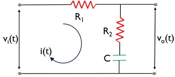
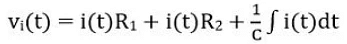
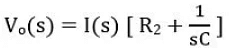
- First, we will apply KVL in the above circuit. Suppose i(t) is the current flowing through the loop. Thus, for loop 1,lag compensator eq1
- We know to determine the response of the system; its transfer function must be determined.
- The transfer function is given as the ratio of output to input in the frequency domain.
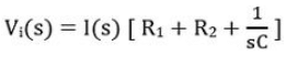
- So, further we will take the Laplace transform of the above equation,
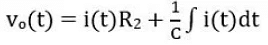
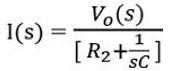
- Now considering loop 2,
- Again considering the Laplace transform:
- Further
- On substituting the above value of I(s) in Laplace equation of input loop, we will get,
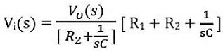
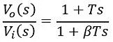
- On simplifying
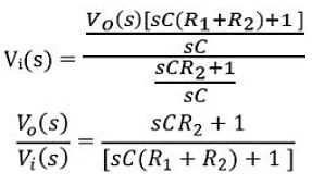
- Further
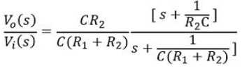
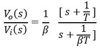
- The general expression is given as:
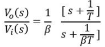
- Hence, on comparison
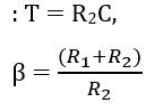
Hence, this shows that the zero of the lag compensator will be present at s = -1/T and pole will be at s = -1/βT. Since β is greater than 1, thus pole of the transfer function is more dominating than the zero. The figure below represents the pole-zero plot of the lag compensator: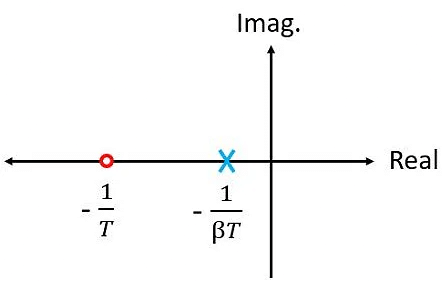
Generally, β is considered as 10. This is the reason when lag compensator is serially connected to the control system; then a negative phase angle is introduced.
Lag Angle
Now proceeding towards determining the maximum lag angle offered by the compensator at a certain frequency.
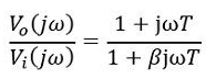
- Since
- Further
- Substituting s = jω
- Therefore, the magnitude will be given as:
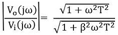
- So, the phase angle will be:
Ф = tan-1 ωT - tan-1ωβT - The phase angle of the lag compensator shows similarity with the lead compensator, which is given as:
Ф = tan-1 ωT - tan-1ωαT - where the only difference is β>1
- Now we will determine the particular frequency at which phase angle ɸ is maximum,
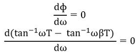
- Thus
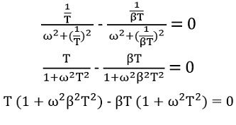
- Further
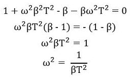
- So, we will get,
ωm = 1/T/√β - Furthermore,
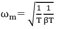
- Thus, it is clear that at this particular frequency, phase lag will be maximal.
- Here ωm is the geometric mean of two corner frequencies,
: ωc1 = 1/T
ωc2 = 1/βT
Advantages of Lag Compensator
- A phase lag network offers high gain at low frequency. Thus, it performs the function of a low pass filter.
- The introduction of this network increases the steady-state performance of the system.
- The lag network offers a reduction in bandwidth and this provides longer rise time and settling time and so the transient response.
Disadvantages of Lag Compensator
- In lag compensator, the attenuation offered by it shifts the gain crossover frequency to a lower point, thereby decreasing the bandwidth.
- Though the system response is longer due to decreased bandwidth; however, the response is quite slow.
- A control system with a lag network shows more sensitivity towards variation in the parameters than a system with a lead network.
- Like in lead compensator, in lag compensator also, due to the addition of external network, some attenuation is introduced. So, the overall gain must be increased to handle the attenuation. But this will increase the requirement of more elements and so the cost and space requirement.
- A lad compensator somewhat acts as a proportional plus integral controller hence adversely affects the stability of the system.
The document Short Notes: Lag Compensator | Control Systems - Electrical Engineering (EE) is a part of the Electrical Engineering (EE) Course Control Systems.
All you need of Electrical Engineering (EE) at this link: Electrical Engineering (EE)
|
53 videos|107 docs|40 tests
|
About this Document

4.69/5
Rating

Oct 01, 2025
Last updated
Related Exams
Document Description: Short Notes: Lag Compensator for Electrical Engineering (EE) 2025 is part of Control Systems preparation.
The notes and questions for Short Notes: Lag Compensator have been prepared according to the Electrical Engineering (EE) exam syllabus. Information about Short Notes: Lag Compensator covers topics
like Introduction and Short Notes: Lag Compensator Example, for Electrical Engineering (EE) 2025 Exam. Find important definitions, questions, notes, meanings, examples, exercises and tests below for Short Notes: Lag Compensator.
Introduction of Short Notes: Lag Compensator in English is available as part of our Control Systems
for Electrical Engineering (EE) & Short Notes: Lag Compensator in Hindi for Control Systems course.
Download more important topics related with notes, lectures and mock test series for Electrical Engineering (EE)
Exam by signing up for free. Electrical Engineering (EE): Short Notes: Lag Compensator | Control Systems - Electrical Engineering (EE)
Description
Full syllabus notes, lecture & questions for Short Notes: Lag Compensator | Control Systems - Electrical Engineering (EE) - Electrical Engineering (EE) | Plus excerises question with solution to help you revise complete syllabus for Control Systems | Best notes, free PDF download
Information about Short Notes: Lag Compensator
In this doc you can find the meaning of Short Notes: Lag Compensator defined & explained in the simplest way possible. Besides explaining types of
Short Notes: Lag Compensator theory, EduRev gives you an ample number of questions to practice Short Notes: Lag Compensator tests, examples and also practice Electrical Engineering (EE)
tests

Related Searches
past year papers
,Short Notes: Lag Compensator | Control Systems - Electrical Engineering (EE)
,Exam
,practice quizzes
,study material
,Extra Questions
,Short Notes: Lag Compensator | Control Systems - Electrical Engineering (EE)
,Sample Paper
,MCQs
,Short Notes: Lag Compensator | Control Systems - Electrical Engineering (EE)
,shortcuts and tricks
,mock tests for examination
,ppt
,Objective type Questions
,Important questions
,Previous Year Questions with Solutions
,Viva Questions
,Free
,Semester Notes
,Summary
,video lectures
;


Additional Information about Short Notes: Lag Compensator for Electrical Engineering (EE) Preparation
Short Notes: Lag Compensator Free PDF Download
The Short Notes: Lag Compensator is an invaluable resource that delves deep into the core of the Electrical Engineering (EE) exam.
These study notes are curated by experts and cover all the essential topics and concepts, making your preparation more efficient and effective.
With the help of these notes, you can grasp complex subjects quickly, revise important points easily,
and reinforce your understanding of key concepts. The study notes are presented in a concise and easy-to-understand manner,
allowing you to optimize your learning process. Whether you're looking for best-recommended books, sample papers, study material,
or toppers' notes, this PDF has got you covered. Download the Short Notes: Lag Compensator now and kickstart your journey towards success in the Electrical Engineering (EE) exam.
Importance of Short Notes: Lag Compensator
The importance of Short Notes: Lag Compensator cannot be overstated, especially for Electrical Engineering (EE) aspirants.
This document holds the key to success in the Electrical Engineering (EE) exam.
It offers a detailed understanding of the concept, providing invaluable insights into the topic.
By knowing the concepts well in advance, students can plan their preparation effectively.
Utilize this indispensable guide for a well-rounded preparation and achieve your desired results.
Short Notes: Lag Compensator
Short Notes: Lag Compensator Notes offer in-depth insights into the specific topic to help you master it with ease.
This comprehensive document covers all aspects related to Short Notes: Lag Compensator.
It includes detailed information about the exam syllabus, recommended books, and study materials for a well-rounded preparation.
Practice papers and question papers enable you to assess your progress effectively.
Additionally, the paper analysis provides valuable tips for tackling the exam strategically.
Access to Toppers' notes gives you an edge in understanding complex concepts.
Whether you're a beginner or aiming for advanced proficiency, Short Notes: Lag Compensator Notes on EduRev are your ultimate resource for success.
Short Notes: Lag Compensator Electrical Engineering (EE) Questions
The "Short Notes: Lag Compensator Electrical Engineering (EE) Questions" guide is a valuable resource for all aspiring students preparing for the
Electrical Engineering (EE) exam. It focuses on providing a wide range of practice questions to help students gauge
their understanding of the exam topics. These questions cover the entire syllabus, ensuring comprehensive preparation.
The guide includes previous years' question papers for students to familiarize themselves with the exam's format and difficulty level.
Additionally, it offers subject-specific question banks, allowing students to focus on weak areas and improve their performance.
Study Short Notes: Lag Compensator on the App
Students of Electrical Engineering (EE) can study Short Notes: Lag Compensator alongwith tests & analysis from the EduRev app,
which will help them while preparing for their exam. Apart from the Short Notes: Lag Compensator,
students can also utilize the EduRev App for other study materials such as previous year question papers, syllabus, important questions, etc.
The EduRev App will make your learning easier as you can access it from anywhere you want.
The content of Short Notes: Lag Compensator is prepared as per the latest Electrical Engineering (EE) syllabus.
|
© EduRev
|
Education Revolution
|


|


Signup on EduRev and stay on top of your study goals
10M+ students crushing their study goals daily