Lattice Network | Network Theory (Electric Circuits) - Electrical Engineering (EE) PDF Download

Introduction
The Lattice Network in Network Analysis is a symmetrical and balanced with four arms as shown in the given Fig. (a). The arms consisting impedance ZA are called series arms of the lattice network. The arms consisting impedance ZB are called shunt or diagonal arms. The lattice network can be rearranged in the bridge structure as shown in the given Fig. (b) which is very suitable for the analysis of the lattice network.
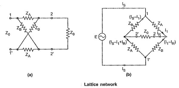
As lattice network is a symmetrical network, let us derive expressions for the characteristic impedance (Z0) and propagation constant (γ). It is very convenient to use bridge structure of the lattice network for the calculation of propagation constant.
Characteristic Impedance (Z0)
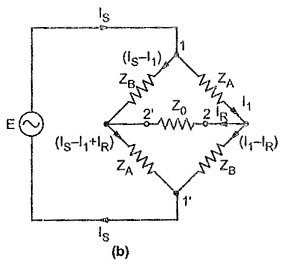
Consider the Fig. (b)
Consider closed path 1-2-2′-1′-1, applying KVL, we get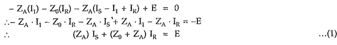
Consider closed path 1-2′-2-1′-1, applying KVL, we get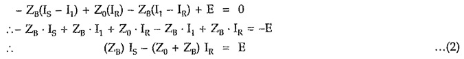
From equation (1),
From equation (2),
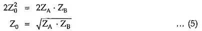
Equating equations (3) and (4),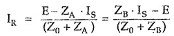

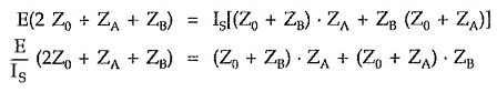
But by the property of symmetrical network, the input impedance of the network terminated in its characteristic impedance is equal to Z0.
Let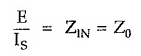
Putting value of E/Is in above equation,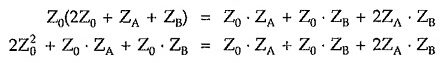
(B) In terms of open and short circuit impedances
For the calculation of open and short circuit impedances arranging bridge structure of the lattice network as shown in the given Fig. (a) and (b).
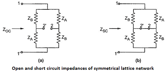
Consider Fig. (a), Consider Fig. (b),

Multiplying equations (6) and (7) , we can write,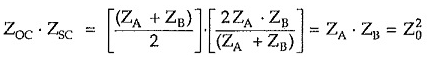

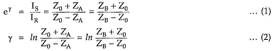
Propagation Constant (γ)
For any symmetrical network, propagation constant can be expressed as,
Consider equations for current IR given by equation (3) and (4) derived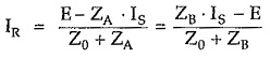
But we know that E = Is . Z0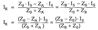
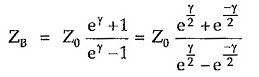
Impedances ZA and ZB in terms of characteristic impedance (Z0) and propagation constant (γ)
Consider equation,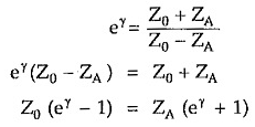
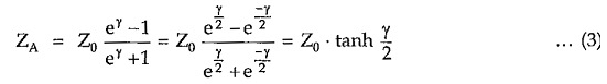
Similarly,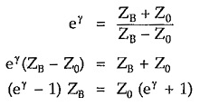

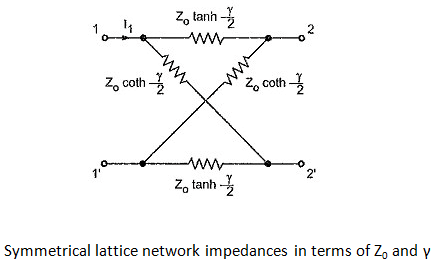
Hence lattice network with impedances expressed in terms of characteristic impedance and propagation constant is as shown in the given Figure.
After detail analysis of some of the important symmetrical networks now consider analysis of typical asymmetrical networks.
|
68 videos|88 docs|62 tests
|


mock tests for examination
,Lattice Network | Network Theory (Electric Circuits) - Electrical Engineering (EE)
,study material
,past year papers
,Sample Paper
,Free
,Summary
,MCQs
,Lattice Network | Network Theory (Electric Circuits) - Electrical Engineering (EE)
,Objective type Questions
,ppt
,Important questions
,Extra Questions
,Semester Notes
,Lattice Network | Network Theory (Electric Circuits) - Electrical Engineering (EE)
,Viva Questions
,video lectures
,practice quizzes
,shortcuts and tricks
,Previous Year Questions with Solutions
,Exam
;


Lattice Network Free PDF Download
Importance of Lattice Network
Lattice Network Notes
Lattice Network Electrical Engineering (EE) Questions
Study Lattice Network on the App
|
© EduRev
|
Education Revolution
|


|


