Electrical Engineering (EE) Exam > Electrical Engineering (EE) Notes > Network Theory (Electric Circuits) > DC Circuit Theory
DC Circuit Theory | Network Theory (Electric Circuits) - Electrical Engineering (EE) PDF Download
| Table of contents |
|
| Introduction |
|
| Electrical Voltage |
|
| Electrical Current |
|
| Electron Flow |
|
| DC Circuit Theory of Resistance |
|
| Summary |
|

Introduction
- Basic DC circuit theory looks at how an electric circuit is an interconnection of electrical elements and that electrical current is the flow of charge, measured in amperes (A) being pushed around a closed circuit by a potential difference (electromotive force) known as voltage, measured in volts (V).
- All materials are made up from atoms, and all atoms consist of protons, neutrons and electrons. Protons, have a positive electrical charge. Neutrons have no electrical charge (that is they are Neutral), while Electrons have a negative electrical charge. Atoms are bound together by powerful forces of attraction existing between the atom's nucleus and the electrons in its outer shell.
- When these protons, neutrons and electrons are together within the atom they are happy and stable. But if we separate them from each other they want to reform and start to exert a potential of attraction called a potential difference.
- Now if we create a closed circuit these loose electrons will start to move and drift back to the protons due to their attraction creating a flow of electrons. This flow of electrons is called an electrical current. The electrons do not flow freely through the circuit as the material they move through creates a restriction to the electron flow. This restriction is called resistance.
- Then all basic electrical or electronic circuits consist of three separate but very much related electrical quantities called: Voltage, (V), Current, (I) and Resistance, (Ω)

Electrical Voltage
- In Dc circuit theory, voltage, (V) is the potential energy of an electrical supply stored in the form of an electrical charge. Voltage can be thought of as the force that pushes electrons through a conductor and the greater the voltage the greater is its ability to “push” the electrons through a given circuit.
- As energy has the ability to do work this potential energy can be described as the work required in joules to move electrons in the form of an electrical current around a circuit from one point or node to another.
- Then the difference in voltage between any two points, connections or junctions (called nodes) in a circuit is known as the Potential Difference, (p.d.) commonly called the Voltage Drop.
- The Potential difference between two points is measured in Volts with the circuit symbol V, or lowercase “v“, although Energy, E lowercase “e” is sometimes used to indicate a generated emf (electromotive force). Then the greater the voltage, the greater is the pressure (or pushing force) and the greater is the capacity to do work.
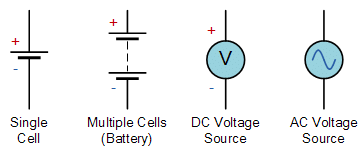
- A voltage source that is unchanging and constant over time is called a DC Voltage. While a voltage source that varies periodically in amplitude over time is called an AC voltage. Whether an AC or DC supply, voltage is measured in volts, with one volt being defined as the electrical pressure required to force an electrical current of one ampere through a resistance of one Ohm.
- While voltages are generally expressed in Volts, prefixes are used to denote sub-multiples of the voltage present, such as microvolts (μV = 10-6 V), millivolts (mV = 10-3 V) or kilovolts (kV = 103 V). Note that voltage can be either positive or negative in amplitude.
- Batteries, power supplies or solar cells produce a D.C. (direct current) voltage source of a fixed value and polarity. For example, 5v, 12v, -9v, etc. A.C. (alternating current) voltage sources on the other hand such as those available for homes, offices and industrial applications have a value relating to the power they supply. The voltage and frequency of mains alternating current (AC) electricity used in homes is typically 230 volts AC (230V) in the United kingdom and 110 volts AC (110V) in the USA.
- General electronic circuits operate on low voltage DC battery supplies of between 1.5V and 24V dc The circuit symbol for a constant voltage source usually given as a battery symbol with a positive, + and negative, – sign indicating the direction of the polarity. The circuit symbol for an alternating voltage source is a circle with a sine wave inside.
Question for DC Circuit TheoryTry yourself: What is the unit of voltage in an electrical circuit?View Solution
Voltage Symbols
- A simple relationship can be made between a tank of water and a voltage supply. The higher the water tank above the outlet the greater the pressure of the water as more energy is released, the higher the voltage the greater the potential energy as more electrons are released.
- Voltage is always measured as the difference between any two points in a circuit and the voltage between these two points is generally referred to as the “Voltage drop“. Note that voltage can exist across a circuit without current, but current cannot exist without voltage and as such any voltage source whether DC or AC likes an open or semi-open circuit condition but hates any short circuit condition as this can destroy it.
Electrical Current
- In DC circuit theory, electrical Current, (I) is the movement or flow of electrical charge and is measured in Amperes, symbol i, for intensity). It is the continuous and uniform flow (called a drift) of electrons (the negative particles of an atom) around a circuit that are being “pushed” by the voltage source. In reality, electrons flow from the negative (–ve) terminal to the positive (+ve) terminal of the supply and for ease of circuit understanding conventional current flow assumes that the current flows from the positive to the negative terminal.
- Generally in circuit diagrams the flow of current through the circuit usually has an arrow associated with the symbol, I, or lowercase i to indicate the actual direction of the current flow. However, this arrow usually indicates the direction of conventional current flow and not necessarily the direction of the actual flow.
Conventional Current Flow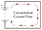
- Conventionally this is the flow of positive charge around a circuit, being positive to negative. The diagram at the left shows the movement of the positive charge (holes) around a closed circuit flowing from the positive terminal of the battery, through the circuit and returns to the negative terminal of the battery. This flow of current from positive to negative is generally known as conventional current flow.
- This was the convention chosen during the discovery of electricity in which the direction of electric current was thought to flow in a circuit. To continue with this line of thought, in all circuit diagrams and schematics, the arrows shown on symbols for components such as diodes and transistors point in the direction of conventional current flow.
- Then Conventional Current Flow gives the flow of electrical current from positive to negative and which is the opposite in direction to the actual flow of electrons.
Question for DC Circuit TheoryTry yourself: Which direction does conventional current flow in a circuit?View Solution
Electron Flow
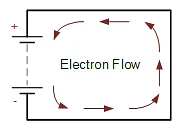
- The flow of electrons around the circuit is opposite to the direction of the conventional current flow being negative to positive.The actual current flowing in an electrical circuit is composed of electrons that flow from the negative pole of the battery (the cathode) and return back to the positive pole (the anode) of the battery.
- This is because the charge on an electron is negative by definition and so is attracted to the positive terminal. This flow of electrons is called Electron Current Flow. Therefore, electrons actually flow around a circuit from the negative terminal to the positive.
- Both conventional current flow and electron flow are used by many textbooks. In fact, it makes no difference which way the current is flowing around the circuit as long as the direction is used consistently. The direction of current flow does not affect what the current does within the circuit. Generally it is much easier to understand the conventional current flow – positive to negative.
- In electronic circuits, a current source is a circuit element that provides a specified amount of current. For example, 1A, 5A, or 10 Amps etc, with the circuit symbol for a constant current source given as a circle with an arrow inside indicating its direction.
- Current is measured in Amps and an amp or ampere is defined as the number of electrons or charge (Q in Coulombs) passing a certain point in the circuit in one second, (t in Seconds).
- Electrical current is generally expressed in Amps with prefixes used to denote micro amps (μA = 10-6A) or milliamps (mA = 10-3A). Note that electrical current can be either positive in value or negative in value depending upon its direction of flow around the circuit.
- Current that flows in a single direction is called Direct Current, or D.C. and current that alternates back and forth through the circuit is known as Alternating Current, or A.C.. Whether AC or DC current only flows through a circuit when a voltage source is connected to it with its “flow” being limited to both the resistance of the circuit and the voltage source pushing it.
- Also, as alternating currents (and voltages) are periodic and vary with time the “effective” or “RMS”, (Root Mean Squared) value given as Irms produces the same average power loss equivalent to a DC current Iaverage . Current sources are the opposite to voltage sources in that they like short or closed circuit conditions but hate open circuit conditions as no current will flow.
- Using the tank of water relationship, current is the equivalent of the flow of water through the pipe with the flow being the same throughout the pipe. The faster the flow of water the greater the current. Note that current cannot exist without voltage so any current source whether DC or AC likes a short or semi-short circuit condition but hates any open circuit condition as this prevents it from flowing.
DC Circuit Theory of Resistance
- Resistance, (R) is the capacity of a material to resist or prevent the flow of current or, more specifically, the flow of electric charge within a circuit. The circuit element which does this perfectly is called the “Resistor”.
- Resistance is a circuit element measured in Ohms, Greek symbol (Ω, Omega) with prefixes used to denote Kilo-ohms (kΩ = 103Ω) and Mega-ohms (MΩ = 106Ω). Note that resistance cannot be negative in value only positive.
DC Circuit Theory for Resistor Symbols
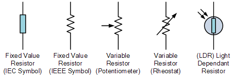
- The amount of resistance a resistor has is determined by the relationship of the current through it to the voltage across it which determines whether the circuit element is a “good conductor” – low resistance, or a “bad conductor” – high resistance. Low resistance, for example 1Ω or less implies that the circuit is a good conductor made from materials such as copper, aluminium or carbon while a high resistance, 1MΩ or more implies the circuit is a bad conductor made from insulating materials such as glass, porcelain or plastic.
- A “semiconductor” on the other hand such as silicon or germanium, is a material whose resistance is half way between that of a good conductor and a good insulator. Hence the name “semi-conductor”. Semiconductors are used to make Diodes and Transistors etc.
- Resistance can be linear or non-linear in nature, but never negative. Linear resistance obeys Ohm’s Law as the voltage across the resistor is linearly proportional to the current through it. Non-linear resistance, does not obey Ohm’s Law but has a voltage drop across it that is proportional to some power of the current.
- Resistance is pure and is not affected by frequency with the AC impedance of a resistance being equal to its DC resistance and as a result can not be negative. Remember that a resistor is an electrical component, while resistance is the slope of the straight line defined by Ohm’s law and as such resistance is always positive, and never negative.
- A resistor is classed as a passive circuit element and as such cannot deliver power or store energy. Instead resistors absorb power that appears as either heat and light. Power in a resistance is always positive regardless of voltage polarity and current direction.
- For very low values of resistance, for example milli-ohms, (mΩ) it is sometimes much easier to use the reciprocal of resistance (1/R) rather than resistance (R) itself. The reciprocal of resistance is called Conductance, symbol (G) and represents the ability of a conductor or device to conduct electricity.
- In other words the ease by which current flows and we can also present current flow as being: i = 1/R * v = Gv. Thus high values of conductance implies a good conductor such as copper while low values of conductance implies a bad conductor such as wood. The standard unit of measurement given for conductance is the Siemen, symbol (S).
- The unit used for conductance is mho (ohm spelt backward), which is symbolized by an inverted Ohm sign ℧. Power can also be expressed using conductance as: p = i2/G = v2G.
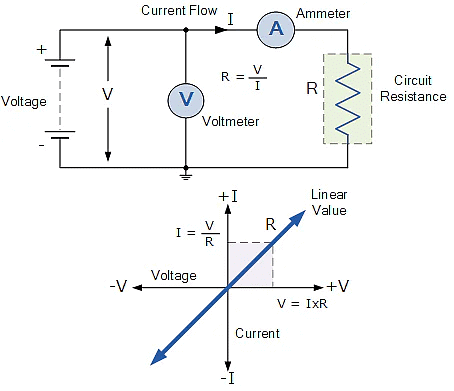
- The relationship between Voltage, (v) and Current, (i) in a circuit of constant Resistance, (R) would produce a straight line i-v relationship with slope equal to the value of the resistance as shown.
Question for DC Circuit TheoryTry yourself: Which type of current flow is opposite to the direction of conventional current flow?View Solution
Summary
- DC circuit theory and how electrical Voltage, Current and Resistance are closely related together. The relationship between Voltage, Current and Resistance forms the basis of Ohm’s law. In a linear circuit of fixed resistance, if we increase the voltage, the current goes up, and similarly, if we decrease the voltage, the current goes down. This means that if the voltage is high the current is high, and if the voltage is low the current is low.
- Likewise, if we increase the resistance, the current goes down for a given voltage and if we decrease the resistance the current goes up. Which means that if resistance is high current is low and if resistance is low current is high.
- Then we can see that current flow around a circuit is directly proportional (∝) to voltage, (V↑ causes I↑) but inversely proportional (1/∝) to resistance as, (R↑ causes I↓).
- The three units is given below.
- Voltage or potential difference is the measure of potential energy between two points in a circuit and is commonly referred to as its ” volt drop “.
- When a voltage source is connected to a closed loop circuit the voltage will produce a current flowing around the circuit.
- In DC voltage sources the symbols +ve (positive) and −ve (negative) are used to denote the polarity of the voltage supply.
- Voltage is measured in Volts and has the symbol V for voltage or E for electrical energy.
- Current flow is a combination of electron flow and hole flow through a circuit.
- Current is the continuous and uniform flow of charge around the circuit and is measured in Amperes or Amps and has the symbol I.
- Current is Directly Proportional to Voltage (I ∝ V)
- The effective (rms) value of an alternating current has the same average power loss equivalent to a direct current flowing through a resistive element.
- Resistance is the opposition to current flowing around a circuit.
- Low values of resistance implies a conductor and high values of resistance implies an insulator.
- Current is Inversely Proportional to Resistance (I 1/∝ R)
- Resistance is measured in Ohms and has the Greek symbol Ω or the letter R.

The document DC Circuit Theory | Network Theory (Electric Circuits) - Electrical Engineering (EE) is a part of the Electrical Engineering (EE) Course Network Theory (Electric Circuits).
All you need of Electrical Engineering (EE) at this link: Electrical Engineering (EE)
|
73 videos|139 docs|62 tests
|
FAQs on DC Circuit Theory - Network Theory (Electric Circuits) - Electrical Engineering (EE)
| 1. What is a DC circuit? |  |
Ans. A DC circuit is a closed loop through which direct current (DC) flows. In a DC circuit, the current flows in one direction continuously, unlike in an alternating current (AC) circuit where the direction of the current changes periodically.
| 2. What are the basic components of a DC circuit? | |
Ans. The basic components of a DC circuit include a power source (such as a battery or DC power supply), conductors (wires) that connect the components, resistors to limit the current flow, and various loads such as light bulbs or electronic devices.
| 3. How do you calculate voltage, current, and resistance in a DC circuit? | |
Ans. Voltage (V) in a DC circuit can be calculated using Ohm's Law: V = I * R, where I is the current in the circuit and R is the resistance. Current (I) can be calculated as I = V / R, and resistance (R) can be calculated as R = V / I.
| 4. What is the difference between series and parallel DC circuits? | |
Ans. In a series DC circuit, the components are connected in a single path, so the current flow through each component is the same. In a parallel DC circuit, the components are connected in multiple paths, allowing the current to split and flow through different branches.
| 5. How do you analyze and solve DC circuit problems using Kirchhoff's laws? | |
Ans. Kirchhoff's laws, including Kirchhoff's Voltage Law (KVL) and Kirchhoff's Current Law (KCL), can be used to analyze and solve complex DC circuit problems. KVL states that the sum of the voltages around any closed loop in a circuit is zero, while KCL states that the sum of currents entering a node is equal to the sum of currents leaving the node.
About this Document

4.71/5
Rating

Oct 01, 2025
Last updated
Document Description: DC Circuit Theory for Electrical Engineering (EE) 2025 is part of Network Theory (Electric Circuits) preparation.
The notes and questions for DC Circuit Theory have been prepared according to the Electrical Engineering (EE) exam syllabus. Information about DC Circuit Theory covers topics
like Introduction, Electrical Voltage, Electrical Current, Electron Flow, DC Circuit Theory of Resistance, Summary and DC Circuit Theory Example, for Electrical Engineering (EE) 2025 Exam. Find important definitions, questions, notes, meanings, examples, exercises and tests below for DC Circuit Theory.
Introduction of DC Circuit Theory in English is available as part of our Network Theory (Electric Circuits)
for Electrical Engineering (EE) & DC Circuit Theory in Hindi for Network Theory (Electric Circuits) course.
Download more important topics related with notes, lectures and mock test series for Electrical Engineering (EE)
Exam by signing up for free. Electrical Engineering (EE): DC Circuit Theory | Network Theory (Electric Circuits) - Electrical Engineering (EE)
Description
Full syllabus notes, lecture & questions for DC Circuit Theory | Network Theory (Electric Circuits) - Electrical Engineering (EE) - Electrical Engineering (EE) | Plus excerises question with solution to help you revise complete syllabus for Network Theory (Electric Circuits) | Best notes, free PDF download
Information about DC Circuit Theory
In this doc you can find the meaning of DC Circuit Theory defined & explained in the simplest way possible. Besides explaining types of
DC Circuit Theory theory, EduRev gives you an ample number of questions to practice DC Circuit Theory tests, examples and also practice Electrical Engineering (EE)
tests

Related Searches
Previous Year Questions with Solutions
,Extra Questions
,practice quizzes
,DC Circuit Theory | Network Theory (Electric Circuits) - Electrical Engineering (EE)
,Free
,Summary
,Viva Questions
,MCQs
,Important questions
,Exam
,Sample Paper
,shortcuts and tricks
,mock tests for examination
,ppt
,past year papers
,study material
,DC Circuit Theory | Network Theory (Electric Circuits) - Electrical Engineering (EE)
,DC Circuit Theory | Network Theory (Electric Circuits) - Electrical Engineering (EE)
,video lectures
,Semester Notes
,Objective type Questions
;


Additional Information about DC Circuit Theory for Electrical Engineering (EE) Preparation
DC Circuit Theory Free PDF Download
The DC Circuit Theory is an invaluable resource that delves deep into the core of the Electrical Engineering (EE) exam.
These study notes are curated by experts and cover all the essential topics and concepts, making your preparation more efficient and effective.
With the help of these notes, you can grasp complex subjects quickly, revise important points easily,
and reinforce your understanding of key concepts. The study notes are presented in a concise and easy-to-understand manner,
allowing you to optimize your learning process. Whether you're looking for best-recommended books, sample papers, study material,
or toppers' notes, this PDF has got you covered. Download the DC Circuit Theory now and kickstart your journey towards success in the Electrical Engineering (EE) exam.
Importance of DC Circuit Theory
The importance of DC Circuit Theory cannot be overstated, especially for Electrical Engineering (EE) aspirants.
This document holds the key to success in the Electrical Engineering (EE) exam.
It offers a detailed understanding of the concept, providing invaluable insights into the topic.
By knowing the concepts well in advance, students can plan their preparation effectively.
Utilize this indispensable guide for a well-rounded preparation and achieve your desired results.
DC Circuit Theory Notes
DC Circuit Theory Notes offer in-depth insights into the specific topic to help you master it with ease.
This comprehensive document covers all aspects related to DC Circuit Theory.
It includes detailed information about the exam syllabus, recommended books, and study materials for a well-rounded preparation.
Practice papers and question papers enable you to assess your progress effectively.
Additionally, the paper analysis provides valuable tips for tackling the exam strategically.
Access to Toppers' notes gives you an edge in understanding complex concepts.
Whether you're a beginner or aiming for advanced proficiency, DC Circuit Theory Notes on EduRev are your ultimate resource for success.
DC Circuit Theory Electrical Engineering (EE) Questions
The "DC Circuit Theory Electrical Engineering (EE) Questions" guide is a valuable resource for all aspiring students preparing for the
Electrical Engineering (EE) exam. It focuses on providing a wide range of practice questions to help students gauge
their understanding of the exam topics. These questions cover the entire syllabus, ensuring comprehensive preparation.
The guide includes previous years' question papers for students to familiarize themselves with the exam's format and difficulty level.
Additionally, it offers subject-specific question banks, allowing students to focus on weak areas and improve their performance.
Study DC Circuit Theory on the App
Students of Electrical Engineering (EE) can study DC Circuit Theory alongwith tests & analysis from the EduRev app,
which will help them while preparing for their exam. Apart from the DC Circuit Theory,
students can also utilize the EduRev App for other study materials such as previous year question papers, syllabus, important questions, etc.
The EduRev App will make your learning easier as you can access it from anywhere you want.
The content of DC Circuit Theory is prepared as per the latest Electrical Engineering (EE) syllabus.
|
© EduRev
|
Education Revolution
|


|


Signup to see your scores
go up within 7 days!
Access 1000+ FREE Docs, Videos and Tests
Takes less than 10 seconds to signup