Electrical Engineering (EE) Exam > Electrical Engineering (EE) Notes > Power Electronics > Single Phase Full Wave Diode Rectifier
Single Phase Full Wave Diode Rectifier | Power Electronics - Electrical Engineering (EE) PDF Download
Introduction
- The diode works only when it is in forward bias, only the current flows through p-n junction diode and output current across the load is found.
- If two diodes are connected in such a way that one diode conducts during one half of the input voltage and the other one conducts during the next half of the cycle, in a unidirectional can flow through the load during the full cycle of the impact voltage. This is known as full wave rectifier.

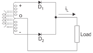
- According to the diagram given below a center tapped transformer D1, and D2 are two p-n junction diodes with similar characteristics D1 conducts for negative half of the output voltage. Thus we get output voltage and the output current for the entire input cycle.
Circuit Diagram of Full Wave Diode Rectifier
The circuit diagram of the full wave diode rectifier given below,
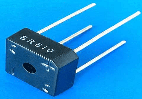
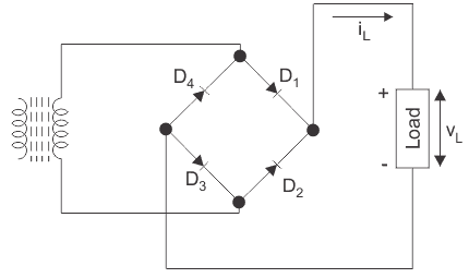
Full wave rectification can also be achieved using a bridge rectifier which is made of four diodes.
- According to the figure, when D1 and D3 are forward biased, they conduct but D2 and D4 and on D1 and D3 are reverse biased in both cases load current in the same direction.
- Bridge rectifier has several advantages over simple full wave rectifier. It performance and efficiency is better than that of the simple full time rectifier.
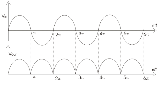
Input Voltage and Output Voltage Waveform

Now, different parameters for a full wave rectifier is given below:
The average of load current (Idc):
Let, the load current be iL = Imsinωt
Ripple factor of a full-wave rectifier is equal to
The document Single Phase Full Wave Diode Rectifier | Power Electronics - Electrical Engineering (EE) is a part of the Electrical Engineering (EE) Course Power Electronics.
All you need of Electrical Engineering (EE) at this link: Electrical Engineering (EE)
|
5 videos|52 docs|46 tests
|
Related Searches


