Introduction to Analog Communication | Communication System - Electronics and Communication Engineering (ECE) PDF Download
| Table of contents |

|
| Analog Communication |

|
| Signals |

|
| Analog Communication System |

|
| Analog vs. Digital |

|
Analog Communication
- Analog communication is made from two words analog and communication. Analog refers to the continuous time-varying signal. Communication refers to exchanging information between two or more than two sources. Analog communication means communication with the help of analog signals.
- The analog communication is communication from the sender to the receiver in the form of an analog signal. The analog signal is a continuous time varying signal. The example of analog signal is sound waves. The signals that continuously vary with time are the examples of an analog signal, such as audio and video signals.
What is communication?
- The transmission of information from one end to the other is known as communication. In electronics system, the data is transmitted through the channel present between the transmitting end and the receiving end. The additional devices are used with communication channel to prevent the signal from external disturbances. The data is present in the form of analog signal, which is a form of energy.
- The essential concept of the analog communication is modulation. It helps in removing the noise or external disturbances from the data, which may deteriorate the quality of the signal being transmitted.
Signals
The signal is an electromagnetic wave that carries information from one point to another. It can travel through different mediums, such as air, vacuum, water, and solid. In electronics, the signal is defined as a current, voltage, or wave carrying information and traveling long distances. The speed of a signal wave is equal to the speed of light. 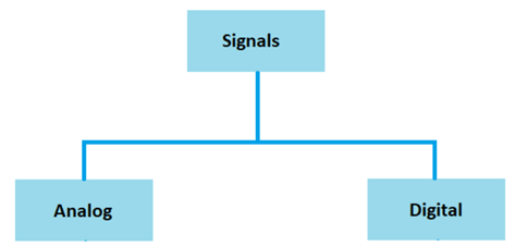 There are two types of signals, analog and digital. Analog refers to the data transmission in analog or continuous form, while digital refers to the data transmission in the form of bits. The bits are represented by 0 (LOW) and 1 (HIGH).
Analog signals
Analog signals are continuous time-varying signals. It means that these signals are the function of time.
Or
An Analog signal is a signal whose characteristics, such as voltage, amplitude, or frequency, vary with time. The common shape of an analog signal is the sinusoidal wave.
It is shown below:
Examples of analog signals are electrical signals, light signals, speech signals, etc. Radio signals are also categorized as analog signals. Every signal requires a medium to propagation. For example,
Electrical signals require cables to propagate from one place to another.
Speech signals or voice requires free space to propagate. We can also say that speech signal uses air as a propagation medium. But, noise and distortion in analog signals during transmission are greater than digital signals.
Example: The distance of a car travelling with constant time with a specific time can be considered as an example of an analog signal.
The graph representing will be an inclined line, as shown below: 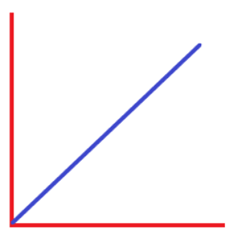 It is continuous in nature.
Types of analog signals
A signal is a type of energy that carries information, like an electrical signal. It is electrical energy that carries information from one source to the other. The analog signals are categorized as periodic signals and non-periodic signals. 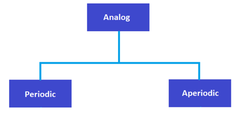 1. Periodic signals: An analog signal that repeats over a period of time is known as the periodic signal, such as sine wave and cosine wave. Periodic signals can be easily represented using mathematical equations.
The cosine wave is shown below:
2. Aperiodic signals: An analog signal that does not repeat over a period of time is known as an Aperiodic signal, such as noise signals. It is a continuous signal but not of the repeated pattern. It isn't easy to represent an aperiodic signal using mathematical equations.
An example of the aperiodic analog signal is shown below: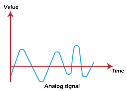
Digital Signal
Digital signals are the signal that represents the data in the form of discrete values. It takes only two values 0 and 1, which is known as bits. The data is transmitted in the form of these bits.
For example,
01000110
It is an 8-bit or 1 byte data.
A common example of the digital signal is shown below:
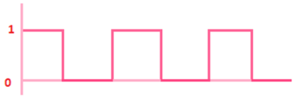
Let's consider another example of a digital signal.
Example: The average marks of the 30 students in a classroom in five subjects can be considered as an example of a digital signal.
The graph is shown below: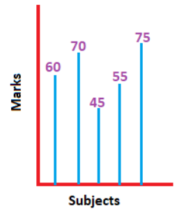
Types of Digital Signals
Digital signals are also categorized as periodic signals and non-periodic signals. 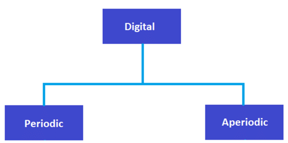
1. Periodic signals: A digital signal that repeats over a period of time is known as periodic signals, such as square wave.
The square wave is shown below: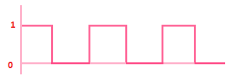
2. Aperiodic signals: A digital signal that does not repeat over a period of time is known as an Aperiodic signal. It is also a discrete signal, but not of repeated pattern.
A common example of the Aperiodic digital signal is shown below: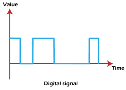
Analog Communication System
The analog communication system refers to a model that helps the data to transmit from one end to the other. It combines elements that work together to establish a network between the sender and receiver. It consists of transducers, transmitter, channel, and receiver. The function of transducers is to convert one form of energy to the other. The channel acts as a medium to transmit electrical information from the transmitter to the receiver.
The block diagram of an analog communication system is shown below: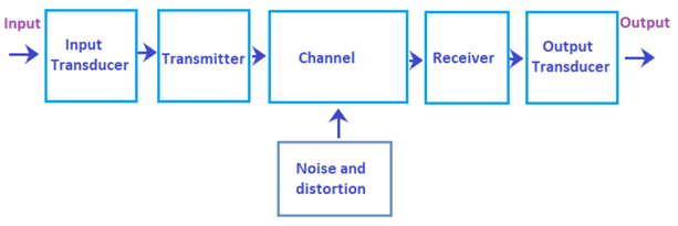 Let's discuss the function of each component in detail:
1. Input transducer
- The input transducer converts the information in the message signal into the electrical energy suitable for transmission. The sources of information are audio, television, computers, etc.
- The frequency range of speech signal is from 300Hz to 3000Hz.
- The frequency of video signals is 4.2M Hz.
- The frequency range of television is 0 Hz to 6000K Hz.
- The output of the input transducer in fed to the transmitter.
2. Transmitter
- The transmitter converts the electrical signal into a form suitable for transmission for the channel. It performs modulation by superimposing the message signal on the high-frequency carrier signal. Thus, different channels have different types of the transmitter. If the channel's characteristic varies, the transmitter must adjust itself to maintain the desired range for effective communication.
- The original signal is known as the message signal or the baseband signal. Transmitter also performs multiplexing, i.e., simultaneous transmission of several signals.
3. Communication channel
Communication channel is a medium to transmit the electrical signal from transmitter to the receiver. The communication can be broadcast or point to point. Broadcast refers to a single sender and multiple receivers, such as radio. Point to point communication refers to the communication between a single sender and a single receiver, such as a telephone. The essential parameter for suitable transmission is bandwidth. The greater the bandwidth, the better will be the transmission.
The communication channel is further categorized as:
- Wired channel
- Wireless channel
(i) Wired channel: The examples of wired channel are twisted pair cables, waveguide, cables, and optical fiber.
- Twisted pair cables: These are the two conducting cables twisted to improve the transmission ability. The twist in the two conductors couples the electric or magnetic fields and prevents the noise interference in the channel. It is commonly used for wire shielding to prevent the data from external noise.
- Waveguides: The waveguides can transmits the electromagnetic waves without any energy less or minimal loss. It is commonly used in radar and microwave communication.
- Optical fiber: An optical fiber is a transmission fiber made up of plastic or glass. It can transmit the data upto hundreds of kilometers without affecting the signal's quality. The transmission is based on TIR (Total Internal Reflection). The diameter of the fiber is as small as the human hair.
(ii) Wireless channel: It is the communication in the form of EM (Electromagnetic waves) from one antenna to the other in space. The transmission depends on the frequency of the EM waves.
4. Interference factors: The interference in the channel is termed as noise and attenuation.
- Attenuation is defined as the loss in the strength of the signal. It is also known as distortion. The attenuation is caused by the passive components in the communication system, such as cables and connectors. It is low in optical fiber as compared to other types of media.
- Noise is a serious factor in the communication system. It is defined as any unwanted interference in the signal during the transmission.
Noise is categorized as:
(i) Internal Noise: The interference that occurs during the signal transmission inside the communication system is known as internal noise. Examples of internal noise are thermal noise, shot noise, etc. Internal noise can also arise from the recombination of the carriers (electrons and holes).
(ii) External Noise: The interference that occurs outside the communication system is known as external noise. The examples of external noise are lighting, ignition, electrical switching, etc.
5. Receiver: The receiver receives information from the channel. It extracts the necessary information from the signal required by the output transducer. The receiver performs the opposite of modulation and multiplexing, i.e., demodulation and demultiplexing. It also amplifies and removes noise from the signal.
6. Output transducer
- The output transducer works reversely as that of the input transducer. It converts the electrical energy into the original signal. We can also say that it makes the information available understandable to the target. Examples of output transducers are loudspeakers, motors, LEDs, etc.
- Both the input and output transducers are important because they convert the signal suitable for transmission and increase the signal's speed.
- The loudspeakers convert the electrical energy to sound.
- The motors convert the electrical energy into motion.
- The LEDs (Light Emitting Diodes) convert the electrical energy to light energy.
- Some channel also uses amplifiers or filters to remove the noise or distortion from the signal. The noise present in the signal can affect the signal's quality. Hence, it's essential to use such components in the circuit.
Function of the analog communication system
- We have already discussed about each component in detail. Let's discuss how the data from one end through the transducer is transmitted to the receiving end. It makes the data available to the receiver without any noise or distortion. Here, we will discuss an example of the speech signal.
- The information first reaches the input transducer. It converts the speech signal to the electrical signal. It is because the communication system can only allow the electrical energy to pass through the system. The electrical signal is further sent to the transmitter. It improves the characteristics of the received signal by modulation and converts it to the suitable form for the channel.
- The information now travels on the channel through different wired or wireless media. After travelling the desired distance, the signal reaches the receiver. It demodulated the signal to recover the original message signal, which is last send to the output transducer. The output transducer converts the electrical signal back to the speech signal.
- Speech plays a major role in human voice, communication through mobile phones, video, etc. But, the back noise in a system is considered as inference and needs to be eliminated from the system. For this, effective filters or amplifiers are used.
Analog vs. Digital
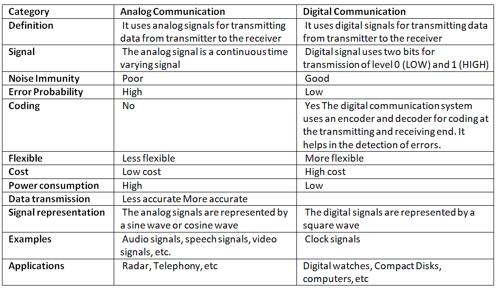
The primary differences between the two communications are that analog communication uses analog signals, which are continuous time varying signals. The digital communication uses digital signals, which are present in discrete form.
Let's discuss some differences between analog and digital communication:
Advantages of analog communication
The advantages of analog communication are as follows:
- Analog signal uses less bandwidth as compared to the digital signal. It is due to the use of amplifier in the analog communication system, which improves the signal and reduces the distortion.
- It provides a more accurate method of representation due to its continuous nature.
- Audio signals are preferred for audio and video transmissions. It is because these signals can be easily modulated and demodulated using Amplitude Modulation and Demodulation.
- Analog signals are easy to process as compared to the digital signals.
- It offers a finite amount of signal resolution.
- Analog signals have high density because it is continuous and requires a medium to transmit.
|
14 videos|44 docs|30 tests
|


