Double Sideband Suppressed Carrier (DSB-SC) Modulation | Communication System - Electronics and Communication Engineering (ECE) PDF Download

Definition
- DSB-SC is an amplitude modulated wave transmission scheme in which only sidebands are transmitted and the carrier is not transmitted as it gets suppressed. DSB-SC is an acronym for Double Sideband Suppressed Carrier.
- The carrier does not contain any information and its transmission results in loss of power. Thus only sidebands are transmitted that contains information. This results in saving of power used in transmission.
- This saved power can be inserted into the 2 sidebands. Hence, ensuring a stronger signal that transmits over long distances. As during suppression, the baseband signal does not get affected in any way.
- As we know that transmission power and bandwidth are the two important parameters in a communication system. Thus, in order to save power and bandwidth, DSB-SC modulation technique is adopted.
- A normal system also termed as Double Sideband Full Carrier (DSB-FC) system, transmits carrier along with the two sidebands. Hence, resulting in a considerable power loss. So, DSB-SC system is used in order to overcome the drawback of DSB-FC system.
Generation of DSB-SC signal
Let’s have a look at the block diagram of the DSB-SC system shown below: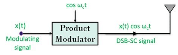 Here, by observing the above figure, we can say that a product modulator generates a DSB-SC signal.
The signal is obtained by the multiplication of baseband signal x(t) with carrier signal cos ωct
By frequency shifting property of Fourier transform: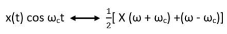
From the above equation, it is clear that only 2 components are present in the spectrum. These two are the two sidebands that are placed at +ωc and -ωc.
Let’s have a look at the pictorial representation of a waveform for DSB-SC system: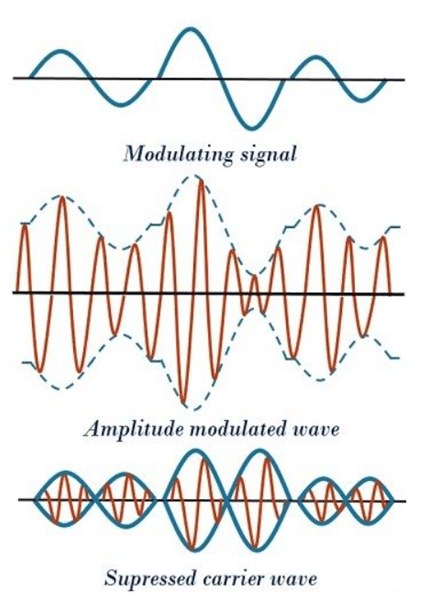
Mathematical Expression
In order to get an exact an idea about the suppression of carrier in DSB-SC system.
Consider the baseband or modulating signal,
x(t) = Ax cos (2πfxt)
and the carrier signal,
c(t) = Ac cos (2πfct)
The mathematical representation of the signal at the output of the product modulator is given as:
s(t) = x(t).c(t)
Further, 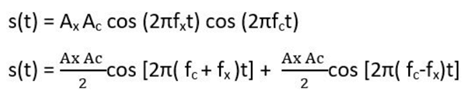
The maximum frequency is fc + fx
The minimum frequency is fc – fx
As we know,
Bandwidth is given as
BW = fmax – fmin
BW = fc + fx – (fc – fx)
BW = 2fx
Thus, at the output, the DSB-SC wave contains a signal whose frequency is twice the frequency of the baseband signal.
Carrier suppression in DSB-SC (Balanced Modulator)
The carrier without any information content is suppressed by a balanced modulator. Its principle of operation is such that, when two signals of the different frequency are passed through a non-linear resistance then an amplitude modulated signal with the suppressed carrier is achieved at the output.
It can be a diode, JFET or BJT that possess non-linear resistance characteristic.
A non-linear device has the capability to produce 2 sidebands with a carrier. But, a balanced mode connection of 2 non-linear devices produces a DSB-SC signal.
Let’s have a look at the circuit of the balanced modulator using diodes: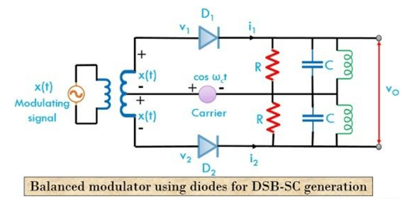 As we can see that the baseband input signal is applied at the input of 2 diodes that are 180⁰ phase reversed with each other through a centre tapped transformer.
Hence the input at D1,
v1 = cos ωct + x(t)
and input at D2,
v2 = cos ωc t – x(t)
At the output side tuned bandpass filter is obtained by parallel connection of RLC circuit.
So, the current through D1 is given as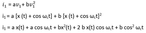
Similarly,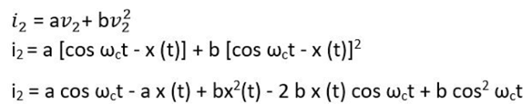
the output voltage is given by
vo = i1 R – i2 R
On substituting the above-given value of i1 and i2 in the output equation, we will have,
vo = R [2 a x(t)] (+ 4b x (t) cos ωct)]
Therefore, the output is,
vo = 2aR x(t) + 4bRx (t) cos ωct
2aR x(t) = modulating signal
4bR x(t) cos ωct = DSB-SC signal
Thus, from the above expression, it is clear that output voltage is a combination of modulating signal along with the DSB-SC signal. After the elimination of the modulating signal, the DSB-SC signal is then passed to the LC bandpass and is received at the output.
Thus we will have,
4bR x(t) cos ωct = K x(t) cos ωct
at the output.
Advantages of DSB-SC modulation
- It provides 100% modulation efficiency.
- Due to suppression of carrier, it consumes less power.
- It provides a larger bandwidth.
Disadvantages of DSB-SC modulation
- It involves a complex detection process.
- Using this technique it is sometimes difficult to recover the signal at the receiver.
- It is an expensive technique when it comes to demodulation of the signal.
Applications of DSB-SC modulation
- During the transmission of binary data, DSB-SC system is used in phase shift keying methods.
- In order to transmit 2 channel stereo signals, DSB signals are used in Television and FM broadcasting.
DSB-SC technique allows us to have a transmission that reduces overall power consumption rate, thereby ensuring a stronger signal at the output.
|
13 videos|49 docs|30 tests
|


Semester Notes
,Sample Paper
,Double Sideband Suppressed Carrier (DSB-SC) Modulation | Communication System - Electronics and Communication Engineering (ECE)
,Double Sideband Suppressed Carrier (DSB-SC) Modulation | Communication System - Electronics and Communication Engineering (ECE)
,video lectures
,Viva Questions
,mock tests for examination
,Exam
,Important questions
,past year papers
,Objective type Questions
,Double Sideband Suppressed Carrier (DSB-SC) Modulation | Communication System - Electronics and Communication Engineering (ECE)
,practice quizzes
,Free
,MCQs
,Extra Questions
,ppt
,Previous Year Questions with Solutions
,Summary
,study material
,shortcuts and tricks
;


Double Sideband Suppressed Carrier (DSB-SC) Modulation Free PDF Download
Importance of Double Sideband Suppressed Carrier (DSB-SC) Modulation
Double Sideband Suppressed Carrier (DSB-SC) Modulation Notes
Double Sideband Suppressed Carrier (DSB-SC) Modulation Electronics and Communication Engineering (ECE) Questions
Study Double Sideband Suppressed Carrier (DSB-SC) Modulation on the App
|
© EduRev
|
Education Revolution
|


|


