Flip-Flops & Its Types


Introduction
A flip-flop in digital electronics is a bistable circuit that has two stable states and is used to store one bit of binary information. The stored data can be changed by applying appropriate inputs. Flip-flops and latches are fundamental storage elements used in sequential logic and appear throughout digital systems such as computers, communication devices and control systems. A flip-flop is the basic storage element in synchronous sequential circuits.
Flip-Flop versus Latch
The principal difference between a latch and a flip-flop is the way the device is controlled:
- Latch - level-triggered. The output follows the input while an enable signal (gate) is at an active level. When the enable returns to inactive, the latch holds the last value.
- Flip-flop - edge-triggered. The output can change only at a specified transition (rising or falling) of a clock signal. Flip-flops are used in synchronous circuits controlled by a clock.
- A gated or clocked SR latch is conceptually the bridge between latches and flip-flops: it becomes a flip-flop when the gating is arranged so that changes occur only on clock edges (master-slave or pulse-triggered arrangements).
Note: Some designs use active-low inputs (signals are active when low). In those cases the meaning of "active" changes accordingly; care is required when reading truth tables or schematic labels.
Basic concepts and timing considerations
- Synchronous vs asynchronous inputs - Synchronous inputs change the stored state only in relation to the clock. Asynchronous inputs such as preset and clear override the clock and force the output immediately to 1 or 0 respectively.
- Edge triggering - A flip-flop that responds to a transition of the clock is edge-triggered. A common implementation uses two cascaded latches (master-slave) or a pulse-triggered flip-flop that samples the input only near the clock edge.
- Level triggering - A latch is transparent while the enable level is active and holds its state when the enable is inactive.
- Setup time - the minimum time before the active clock edge during which the data input must remain stable.
- Hold time - the minimum time after the clock edge during which the data input must remain stable.
- Propagation delay - the time between the clock triggering (or an input change for asynchronous inputs) and the resulting valid change at the output.
- Metastability - if setup/hold requirements are violated or asynchronous signals are sampled, the flip-flop may enter an indeterminate state for some time before resolving; synchroniser chains are used to reduce metastability risk when sampling asynchronous inputs.
Types of flip-flops
There are four basic and widely used types of flip-flops:
- SR flip-flop
- JK flip-flop
- D flip-flop
- T flip-flop
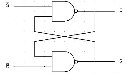
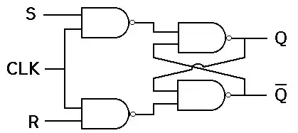
SR (Set-Reset) flip-flop
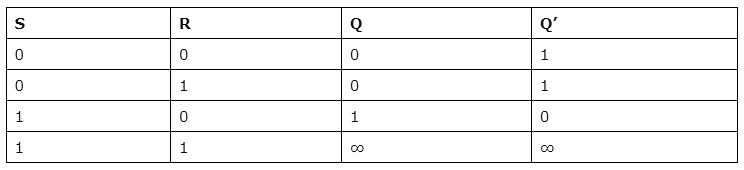
The SR flip-flop has two inputs, S (set) and R (reset). When S is active the output Q is set to 1; when R is active the output Q is reset to 0. If both S and R are inactive, the flip-flop holds its previous state. The combination S = R = 1 is normally considered invalid (indeterminate) for the simple SR latch implementation because it leads to a contradiction for complementary outputs.
The SR flip-flop is the simplest flip-flop and is useful for understanding storage behaviour, but practical designs often prefer other types (JK or D) because they avoid the indeterminate input condition or provide more convenient control.
JK flip-flop
The JK flip-flop is an improved form of the SR flip-flop that removes the invalid (indeterminate) condition when both inputs are asserted. It has two inputs, J and K, and a clock input. The behaviour at the active clock edge is:
- J = 0, K = 0 → no change (Q retains its value).
- J = 1, K = 0 → set (Q → 1).
- J = 0, K = 1 → reset (Q → 0).
- J = 1, K = 1 → toggle (Q → Q').
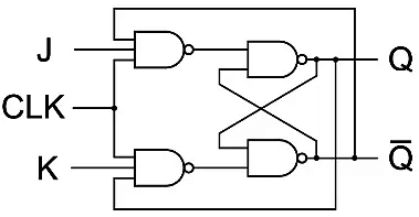
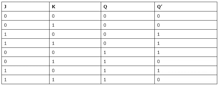
The characteristic equation for a JK flip-flop (next state Q+) can be written as Q+ = J·Q' + K'·Q. The JK flip-flop is versatile and can be wired to act as set/reset, toggle, or hold, hence it is used widely in counters and state machines.
D (Data or Delay) flip-flop
The D flip-flop has a single data input D and a clock input. At the active clock edge the output Q takes the value of D and then holds it until the next active edge. This eliminates indeterminate input combinations and simplifies timing requirements for many designs. D flip-flops are commonly used for data storage, shift registers and synchronisation of asynchronous signals.
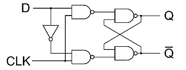
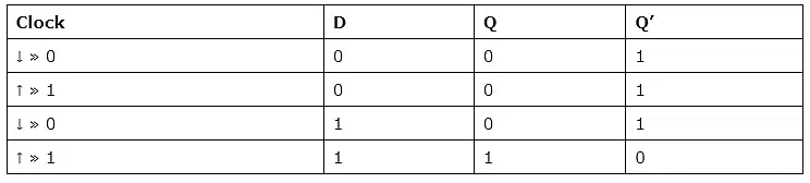
The defining relation for a D flip-flop is Q+ = D (sample on the clock edge).
T (Toggle) flip-flop
The T flip-flop has a single input T and a clock. It toggles the output when T = 1 at the active clock edge, and holds the output when T = 0. A T flip-flop can be obtained by tying J and K of a JK flip-flop together (J = K = T).
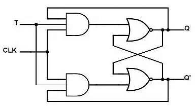
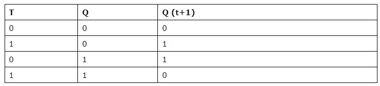
The characteristic relation is Q+ = T ⊕ Q (logical exclusive OR), so when T = 1 the next state is the complement of the present state; when T = 0 the state is unchanged. T flip-flops are convenient for building binary counters and frequency dividers.
Characteristic & excitation tables (concept)
For design and analysis it is useful to know, for each flip-flop type, the characteristic table (gives Q+ as a function of inputs and present Q) and the excitation table (gives required inputs to achieve a desired transition from Q to Q+). These tables are standard design aids when converting one flip-flop type to another or when synthesising sequential circuits.
Practical considerations and common applications
- Counters - T and JK flip-flops are often used to build ripple and synchronous counters.
- Frequency dividers - a T flip-flop toggling on every clock edge divides the clock frequency by two.
- Shift registers - cascaded D flip-flops shift digital data from one stage to the next on each clock.
- Storage registers - arrays of D flip-flops store multi-bit values; used in CPU register files and buffers.
- State machines - flip-flops store the current state; combinational logic determines the next state and outputs.
- Debouncing & synchronisation - flip-flops (often D type) are used to remove mechanical switch bounce and to synchronise external asynchronous signals to a system clock.
Summary
Flip-flops are bistable storage elements essential to sequential digital design. Understanding the differences between SR, JK, D and T flip-flops, their triggering behaviour, timing constraints (setup/hold), and how they are used in practical circuits is fundamental to designing reliable synchronous systems. Choose the flip-flop type according to the application: D for simple sampling and registers, JK or T for counters and toggle functions, and SR for basic set/reset control where the invalid condition is managed.


 | Explore Courses for Computer Science Engineering (CSE) exam |
 | Get EduRev Notes directly in your Google search |