Overview: Electricity | Science Class 10 PDF Download
Electric Current
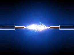
An electric current is the flow of particles, specifically electrons, through wires and other components. It represents how quickly charge moves. When electric charge travels through a conductor, we say there is an electric current in that conductor. In circuits that use metallic wires, the flow of charges is primarily due to electrons. Initially, electric current was thought to be the movement of positive charges, and it was assumed that the current flowed in the same direction as these positive charges. However, in electric circuits, the conventional direction of current flow is actually opposite to that of the electrons, which are negatively charged.
Electric Current Formula and Unit
- The formula for electric current (I) is I = Q/t, where Q is the total charge passing through a section of a conductor in time t.
- The SI unit for electric charge is the coulomb (C), equivalent to the charge of about 6 × 10¹⁸ electrons. Electric current is measured in amperes (A), named after French scientist André-Marie Ampère. One ampere is the flow of one coulomb of charge per second, expressed as 1 A = 1 C/1 s.
- In a simple electric circuit, current flows from the negative terminal to the positive terminal of a cell.
- A typical electric circuit consists of components like a lamp, a switch, and a cell.
- In a torch, the battery (cell) allows the flow of charges, making the bulb light up due to the electric current.
- An ammeter is used to measure electric current in a circuit and is always connected in series with the circuit being measured.
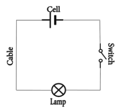
- A switch in a circuit creates a conducting link between the cell and the bulb, allowing current to flow.
- If the circuit is interrupted or breaks, the current immediately stops flowing, and the bulb ceases to glow.
Electric Potential and Potential Difference
Electric Potential Difference is the driving force behind the flow of electric charges in a circuit, much like pressure differences drive water flow.
It is the work done to move a unit charge between two points in a circuit.
Mathematically:
V = Q/W
Unit: Measured in volts (V), where 1 volt = 1 joule/coulomb.
Function: Created by a battery, it pushes charges through a conductor, generating electric current.
Measurement: A voltmeter, connected in parallel, measures this potential difference.
Electric Current and Circuit Diagram Elements
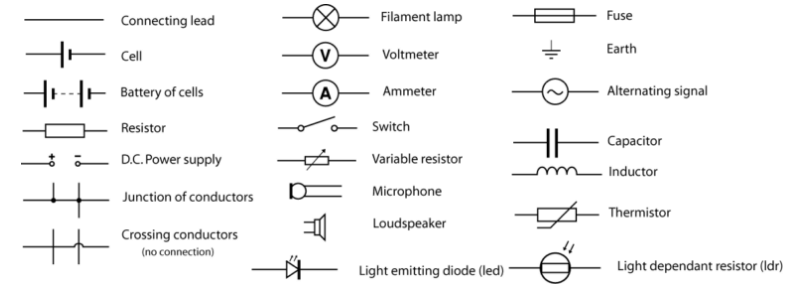 The schematic diagram represents the different components of a circuit; this is the circuit diagram. These symbols represent the common electrical components.
Ohm’s Law and Resistance
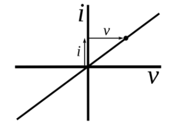
- Ohm's law states that the potential difference across a resistor is directly proportional to the current through it, as long as the temperature stays the same. The formula for Ohm’s law is V = IR.
- The basic components of electricity include voltage, current, and resistance. Ohm’s law shows a simple relationship between these three.
- The resistance of a conductor depends on its length, inversely on its cross-sectional area, and on the material used for the conductor.
Ohm’s Law
Most basic components of electricity are voltage, current, and resistance. Ohm’s law shows a simple relation between these three quantities. Ohm’s law states that the current through a conductor between two points is directly proportional to the voltage across the two points.
Ohm’s Law Formula
Voltage = Current × Resistance
V = I × R
V = voltage, I = current and R = resistance
SI unit of resistance is ohms and is denoted by Ω
This law is one of the most basic laws of electricity. It helps to calculate the power, efficiency, current, voltage, and resistance of an element of an electrical circuit.
Applications of Ohm’s Law: Ohm’s law helps us in determining either voltage, current or impedance or resistance of a linear electric circuit when the other two quantities are known to us. It also makes power calculation simpler.
Resistance of a System of Resistors
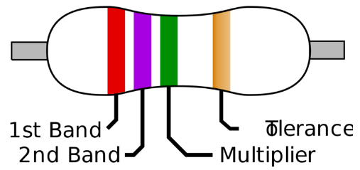
Resistors in Series
A series generally means connected along a line, or in a row, or in an order. In electronics, series resistance means that the resistors are connected one after the other and that there is only one path for current to flow through.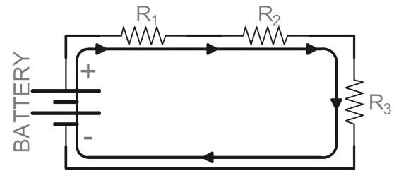
Laws of Series Circuits
- All individual resistances combine to form the total circuit resistance.
- The current remains the same at every point in the circuit.
- All individual voltages total up to the circuit's overall voltage.
Resistors in Parallel
There are many different ways to organize a parallel circuit. In the practical world, most of the wiring is done in parallel so that the voltage to any one part of the network is the same as the voltage supplied to any other part of it.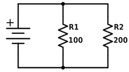
Laws of Parallel Circuits
- The reciprocals of all the individual resistances add up to the reciprocal of the total circuit resistance.
- 1/RT = 1/R1 + 1/R2 + 1/R3 …
- Voltage through the circuit is the same at every point.
- Individual current draws throughout the circuit add up to the total current draw.
Heating Effect of the Electric Current
When a current flows through a conductor, heat energy generates in the conductor. The heating effects of electric current depend on three factors:
- The resistance of the conductor. A higher resistance produces more heat.
- The time for which the current flows. The longer the time the amount of heat production is high.
- Higher the current the amount of heat generation is also large.
Hence the heating effect produced by an electric current, I through a conductor of resistance, R for a time, t is given by H = I2Rt. This equation is the Joule’s equation of electrical heating.
Joule’s law states the amount of heat production in a conductor is :
- Directly proportional to the square of electric current flowing through it.
- Is directly proportional to the resistance of the conductor.
- Directly proportional to the time for which electric current flows through the conductor.
Electric Power
Electric power is the rate at which electrical energy is consumed in a circuit. It can be calculated using the formula:

where:
- P is the power in watts (W),
- V is the potential difference in volts (V),
- I is the current in amperes (A),
- R is the resistance in ohms (Ω).
The SI unit of electric power is the watt (W), where 1 watt is the power used when 1 ampere of current flows through a circuit with a potential difference of 1 volt.
For practical purposes, larger units like kilowatt (kW) are often used, where: 1 kW = 1000 W.
The unit of electric energy is the watt hour (Wh). Electric energy is measured in watt hours (Wh), with the commercial unit being kilowatt hour (kWh), commonly referred to as a ‘unit’ of electricity. One kilowatt hour is equal to: 1 kWh = 3.6 × 10⁶ joules (J).
This unit signifies the energy consumed when 1 kilowatt of power is used for 1 hour.
|
80 videos|569 docs|80 tests
|
FAQs on Overview: Electricity - Science Class 10
| 1. What is the formula for electric current and what unit is it measured in? |  |
| 2. What is the difference between electric potential and potential difference? |  |
| 3. What are the main elements of an electric circuit diagram? |  |
| 4. How does Ohm's Law relate to resistance in a circuit? |  |
| 5. What is the heating effect of electric current and how is it utilized? |  |


