Diagram Based Questions: Electricity

Q1: Answer the following questions based on the diagram given below:
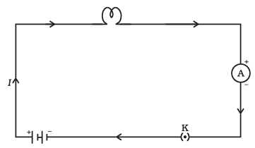
(i) What is the purpose of including a cell in this electric circuit?
Ans: The cell supplies electrical energy to the circuit by creating a potential difference between its terminals. This potential difference pushes charge around the circuit so that current flows and the bulb can light up.
(ii) Explain the function of the electric bulb in this circuit.
Ans: The electric bulb converts electrical energy into light (and some heat). When current passes through its filament, the filament heats up and emits light, so the bulb lights only when the circuit is complete.
(iii) Why is an ammeter included in this circuit, and what does it measure?
Ans: The ammeter is placed in the circuit to measure the electric current flowing through it. It reads the magnitude of current in amperes (A). An ammeter is connected in series so that the same current passes through it as through the rest of the circuit.
(iv) What role does the plug key play in this experiment?
Ans: The plug key acts as a switch that opens or closes the circuit. When the key is closed, the circuit is complete and current flows; when it is opened, the circuit is broken and current stops. This lets us control the bulb and perform simple experiments safely.
(v) What will happen to the electric bulb if the plug key is opened (turned off)?
Ans: If the plug key is opened, the circuit becomes open and no current can flow. As a result, the bulb will stop glowing and remain off until the key is closed again.
Q2: Answer the following questions based on the diagram given below: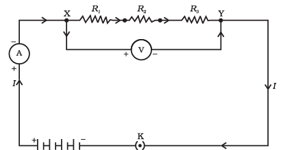
(i) What does the diagram show regarding the arrangement of resistors?
Ans: The diagram shows resistors connected end-to-end along a single path so that the current passes through each resistor one after the other. This arrangement is called a series connection.
(ii) How does the total resistance in a series circuit compare to the individual resistances of the resistors?
Ans: In a series circuit, the total resistance is the sum of all individual resistances. In symbols, Rtotal = R1 + R2 + R3 + ... . The total resistance is therefore greater than any single resistor in the series.
(iii) If two resistors, one with resistance 3 ohms and another with resistance 4 ohms, are connected in series, what is the total resistance of the circuit?
Ans: The total resistance is the sum of the two resistances: 3 Ω + 4 Ω = 7 Ω.
(iv) What happens to the current flowing through each resistor in a series circuit when additional resistors are added to the circuit?
Ans: When additional resistors are added in series, the total resistance of the circuit increases. For the same applied voltage, the overall current decreases according to Ohm's law. The current through each resistor in a series circuit is the same, so every resistor carries the reduced current.
(v) If a 12-volt battery is connected to a series circuit with three resistors, each with a resistance of 6 ohms, what will be the total current flowing through the circuit?
Ans: Use Ohm's law, I = V / R.
Rtotal = 6 Ω + 6 Ω + 6 Ω = 18 Ω.
I = 12 V / 18 Ω = 12/18 A = 2/3 A ≈ 0.67 A.
So the current flowing through the circuit (and through each resistor) is about 0.67 amperes.
Q3: Answer the following questions based on the diagram given below:
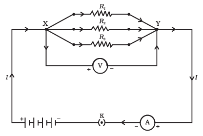
(i) What is meant by resistors in parallel?
Ans: Resistors in parallel are connected so that they share the same two connection points. Each resistor provides a separate path for current, so the total current from the source splits into these parallel branches.
(ii) How does the total resistance of resistors in parallel compare to the individual resistances?
Ans: The total resistance of resistors in parallel is less than the smallest individual resistance in the group. Adding more parallel branches gives more paths for current and so reduces the overall resistance.
(iii) What happens to the total current when resistors are connected in parallel?
Ans: When resistors are connected in parallel, the total resistance falls, so for the same applied voltage the total current supplied by the source increases. The total current is the sum of the currents through each parallel branch.
(iv) Can you explain why appliances in our homes are connected in parallel rather than in series?
Ans: Appliances are connected in parallel so that each one receives the full mains voltage and can work independently. If appliances were in series, one appliance failing or being switched off would interrupt the current to all others, and each appliance would get only a fraction of the voltage.
Ans: To find the total resistance Rtotal of resistors in parallel, use the reciprocal formula:
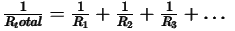
That is, 1/Rtotal = 1/R1 + 1/R2 + 1/R3 + ... . After adding the reciprocals, take the reciprocal of the sum to get Rtotal. For two resistors R1 and R2, a convenient form is Rtotal = (R1 × R2) / (R1 + R2).
FAQs on Diagram Based Questions: Electricity
| 1. What is electricity? |  |
| 2. How is electricity generated? | |
| 3. What is the difference between AC and DC electricity? | |
| 4. What are the units used to measure electricity? | |
| 5. How does electricity travel through a circuit? | |