Pipes in Series and Parallel, Hardy-Cross method | Fluid Mechanics for Civil Engineering - Civil Engineering (CE) PDF Download
Pipes in Series
Pipes arranged in series refer to interconnected pipes of various lengths and diameters forming a pipeline. Imagine a scenario where these series-connected pipes facilitate the discharge of water from a higher water level tank to a lower water level tank, as depicted in the illustration.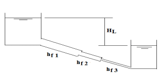
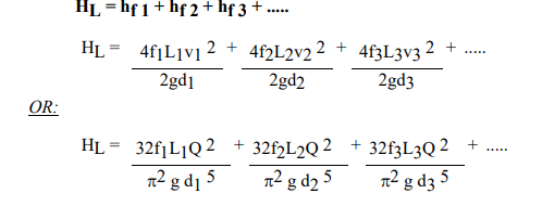
If we disregard secondary losses, it's evident that the overall head loss (HL) between the two tanks comprises solely the cumulative friction losses occurring throughout the pipeline.
The total friction losses within the pipeline amount to the combined friction loss of each individual pipe within it.
Pipes in Parallel
Parallel pipes refer to pipes with varying diameters but identical lengths, where each pipe connects independently to augment the overall discharge capacity. Imagine a scenario where these parallel pipes facilitate the transfer of water from a higher water level tank to a lower water level tank, as illustrated in the figure.
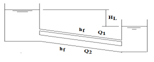
Disregarding minor losses, it's evident that the overall head loss (HL) between the two tanks equals the cumulative friction losses across each individual pipe.
The frictional losses across all pipes remain consistent, and each pipe operates independently in discharging water.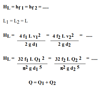
Example 1: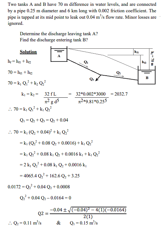
Example 2:
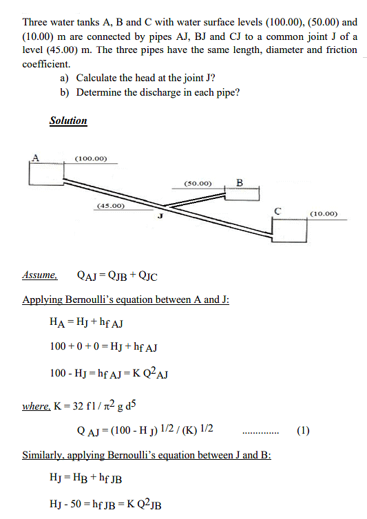
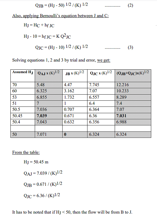
Hardy-Cross Method
The Hardy Cross method applies principles of flow continuity and potential continuity to solve for flow distributions within a pipe network through iterative steps. In pipe flow scenarios, flow conservation signifies that the inflow equals the outflow at every junction. Potential conservation indicates that the total directional head loss along any loop in the system amounts to zero, considering a head loss counted against the flow might actually be a head gain.
The Hardy Cross method relies on two primary assumptions:
- The head losses between any two junctions must remain consistent across all routes connecting these junctions.
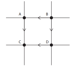 Head loss in Pipe BA + Head loss in Pipe DC = Head loss in Pipe AC + Head loss in Pipe BD
 - The inflow to each junction must equal the outflow from that junction
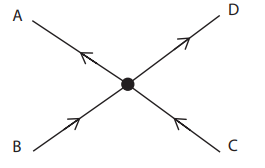
QB + QC = QA + QD
The head balancing method begins with an initial assumption that meets flow continuity at each junction, then adjusts flows until potential continuity is also attained across every loop within the system.
This approach is applicable when the total flow rate is known, and it doesn't necessarily require the head or pressure values at the junctions.
Major loss can be determined as:
Head loss in pipe in which flow is clockwise:
 Head loss in pipe in which flow is counter clockwise:
 Total head loss is constant whether it is measured clockwise or counter-clockwise:
 In the initial assumption, it's presumed that the loss values remain unbalanced.

Then,

It is known that,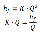
Finally,
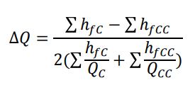 The calculation process will iterate multiple times until the value of ΔQ approaches zero.
Example: Determine the distribution of flowrate?
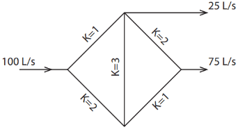
Basic Step:
- Identify the loop or cycle within the network.
- Estimate the initial flow rate and its direction, no unit conversion required into SI units.
- Construct a table to satisfy the equations involved in the Hardy Cross method.
- Redraw the network figure and suggest adjusted flow rates; ΔQ value isn't the final solution.
- Iterate through steps 1 to 4 until ΔQ approaches zero. Suggest revised flow rates as needed.
Ans:
First Trial
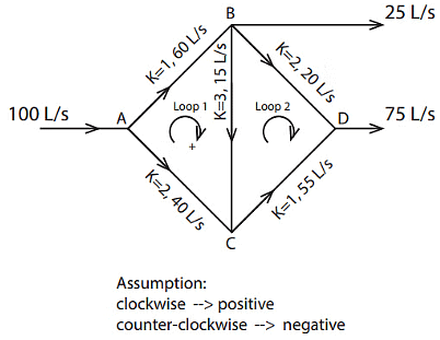
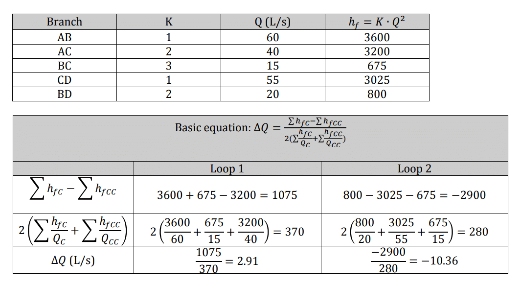
Adjustments to the flow rate values should be made based on the calculated ΔQ value obtained previously.
Modification (add or substrate) rule of thumb:
- Clockwise 🡪 substrate with ΔQ
- Counter-clockwise 🡪 add with ΔQ

New Purpose flow and its direction is:
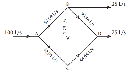
Nonetheless, this doesn't represent the ultimate flow rate as the ΔQ still displays a significant value. A second round of calculations is required. Continue this process iteratively until the ΔQ value approaches nearly zero.
Second Trial
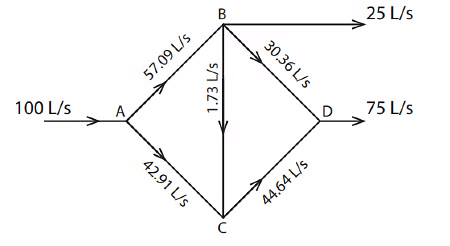
The calculation process should commence using this specific flow rate value.
|
54 videos|141 docs|115 tests
|
FAQs on Pipes in Series and Parallel, Hardy-Cross method - Fluid Mechanics for Civil Engineering - Civil Engineering (CE)
| 1. What are pipes in series and parallel? |  |
| 2. How does the Hardy-Cross method work in civil engineering? |  |
| 3. What is the purpose of analyzing pipes in series and parallel? |  |
| 4. How do you calculate the flow distribution in pipes connected in parallel? |  |
| 5. What are the advantages of using the Hardy-Cross method in pipe network analysis? |  |


