Electrical Engineering (EE) Exam > Electrical Engineering (EE) Notes > Analog and Digital Electronics > Sample and Hold Circuit
Sample and Hold Circuit | Analog and Digital Electronics - Electrical Engineering (EE) PDF Download
Sample and Hold Circuit
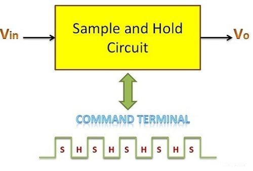
- A Sample and Hold circuit is a special electronic circuit. It takes in a voltage and makes a "sample" of it, then keeps that sample for a set amount of time. The time it takes the circuit to make the sample is called the sampling time. After that, the time it holds onto the sample is called the holding time.
- Usually, the sampling time lasts between 1 to 14 microseconds, but the holding time can be any needed value for the task.
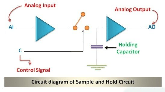
- In this circuit, the key component is the capacitor. It plays a crucial role: it charges up to the highest voltage when the switch is on (during sampling) and then holds onto that voltage when the switch is off (during holding).
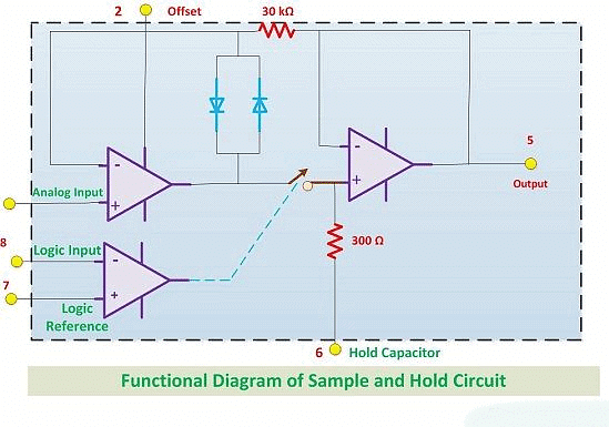
- The circuit diagram for the Sample and Hold circuit is shown below. It uses two operational amplifiers connected through a switch. When the switch is closed, it does the sampling, and when it's open, it does the holding.
- The capacitor connected to the second operational amplifier is nothing but a holding capacitor.
Significance
- The Sample and Hold circuit plays a crucial role in our shift towards digital communication from analog. The reason behind this shift lies in the realm of communication.
- In the comparison between digital and analog communication, digital comes out on top due to its superior reliability and efficiency. The main problem with analog communication is noise interference. This interference makes analog signals less reliable and efficient.
- Now, naturally, all signals start as analog. So, how do we get around this noise issue? This is where the Sample and Hold circuit steps in.
- The Sample and Hold circuit allows us to take samples of the analog signal, and then hold these samples using a capacitor for a specific period of time. This process creates a constant signal. This constant signal can then be converted into a digital signal with the help of analog-to-digital converters.
- So, the Sample and Hold circuit serves as a bridge, helping us convert the analog signals, prone to noise, into stable, reliable digital signals. This transformation is what has driven us towards the use of Sample and Hold circuits in the realm of communication.
- Understanding how a Sample and Hold circuit works is pretty simple when we look at its parts in action. The key pieces in a Sample and Hold circuit are: an N-channel Enhancement MOSFET (a type of switch), a capacitor that stores electric charge, and a precise operational amplifier.
Working of Sample and Hold Circuit
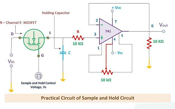
- N-channel Enhancement MOSFET: This acts as the switch in the circuit. The input voltage goes through its "drain" terminal, and a control voltage goes through its "gate" terminal. When a positive pulse of control voltage hits, the MOSFET switches ON, acting like a closed switch. Conversely, when the control voltage is zero, the MOSFET switches OFF, acting like an open switch.
- Charging the Capacitor: When the MOSFET is ON (closed switch), the analog signal at the "drain" terminal flows to the capacitor. The capacitor charges up to its highest value during this time.
- Holding the Charge: When the MOSFET switches OFF (open switch), the capacitor stops charging. Because of the high impedance (resistance to electric current) of the operational amplifier at the end of the circuit, the capacitor can't discharge easily.
- Holding and Sampling Periods: The capacitor holds onto this charge for a set amount of time, known as the holding period. This is the time the capacitor "holds" the sample. The time when the input voltage samples are created is called the sampling period.
- Role of Operational Amplifier (OP-AMP): During the holding period, the output from the circuit is processed by the operational amplifier. This makes the holding period pretty important for the OP-AMP to do its job effectively.
In simple terms, the Sample and Hold circuit uses the MOSFET switch to "grab" a sample of the input voltage and store it in the capacitor. This stored sample stays put until it's needed, ensuring we have stable, reliable signals for further processing. This whole process helps in converting analog signals to digital ones accurately.
Input and Output Waveforms
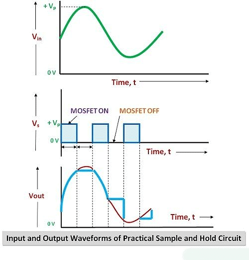
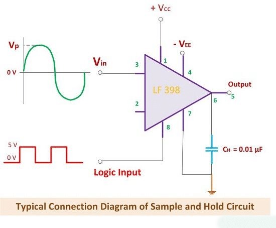
- Looking at the diagram of the Sample and Hold circuit, we can easily see what happens during the ON and OFF times.
- During the ON time, we see the voltage at the output.
- During the OFF time, we see the voltage at the output of the OP-AMP.
Connections
- The connection diagram shows us how the input voltage and control voltage are applied to the OP-AMP.
- It's important to use a capacitor that doesn't leak. Capacitors made of Teflon and polyethylene work well for this purpose.
Special IC:
- In the connection diagram, you might notice "LF 398." This is a special IC designed for Sample and Hold circuits.
Key Point:
- A crucial thing to remember is the frequencies of the analog input signal and control signal.
- For the Sample and Hold circuit to work efficiently, the frequency of the control voltage should be higher than the frequency of the input voltage.
- This way, the analog signal can be sampled twice in one full cycle.
 |
Download the notes
Sample and Hold Circuit
|
Download as PDF |
Download as PDF
Functional Diagram
- The diagram shows us how a Sample and Hold circuit works.
- It helps us understand the process easily.
Performance Parameters
Acquisition Time (TAC): This is how long the capacitor takes to get charged up with the input voltage. It's also called the acquisition time.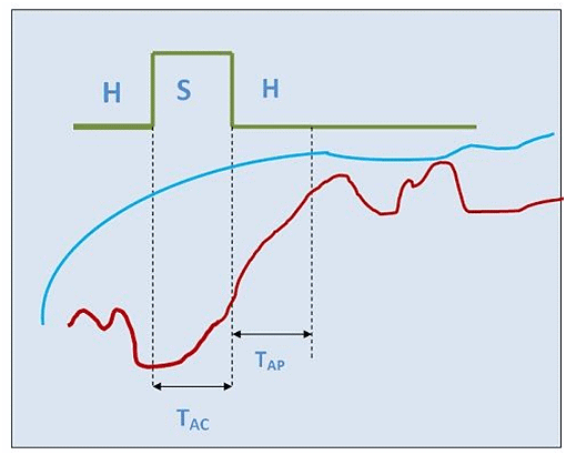
- Aperture Time (TAP): The time it takes for the capacitor to switch from sampling to holding. Because of switch delays, the capacitor keeps charging a bit even after the hold command. This is known as aperture time.
- Voltage Droop: Sometimes, the capacitor loses some charge over time due to leakage. This leads to a drop in voltage. While we ideally want capacitors without leakage, it's tough to achieve. So, there will always be some voltage drop.
- Hold Mode Settling Time: After we give the hold command, the capacitor needs a bit of time to fully settle with the input voltage. This is called the Hold Mode settling time.
Applications of Sample and Hold Circuit
- Used in Data Distribution Systems.
- Found in Sampling Oscilloscopes.
- Important for Data Conversion Systems.
- Used in Digital Voltmeters.
- Helpful in Analog Signal Processing.
- Used in Signal Constructional Filters.
The document Sample and Hold Circuit | Analog and Digital Electronics - Electrical Engineering (EE) is a part of the Electrical Engineering (EE) Course Analog and Digital Electronics.
All you need of Electrical Engineering (EE) at this link: Electrical Engineering (EE)
|
137 videos|144 docs|71 tests
|
Related Searches


