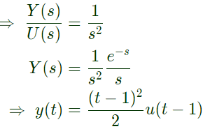
Q21: The impulse response of a system is h(t) = tu(t). For an input u(t - 1), the output is (2013)
(a) 
(b) 
(c) 
(d) 
Ans: (c)
Sol: 
Q22: The input x(t) and output y(t) of a system are related as  The system is (2012)
(a) time-invariant and stable
(b) stable and not time-invariant
(c) time-invariant and not stable
(d) not time-invariant and not stable
Ans: (b)
Sol: 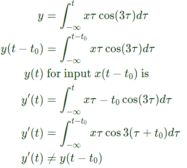 So, system is not time invariant for input xτ = cos(3τ) bounded input
 So, for bounded input, output is not bounded therefore system is not stable.
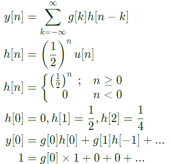
Q23: Let y[n] denote the convolution of h[n] and g[n], where h[n] = (1/2)nu[n] and g[n] is a causal sequence. If y[0] = 1 and y[1] = 1/2, then g[1] equals (2012)
(a) 0
(b) 1/2
(c) 1
(d) 3/2
Ans: (a)
Sol: Given, g[n] is causal sequence
Therefore, g[n] will be zero for n < 0


Q24: Given two continuous time signals x(t) = e−t and y(t) = e−2t which exist for t > 0, the convolution z(t) = x(t)*y(t) is (2011)
(a) e−t−e−2t
(b) e −3t
(c) e+t
(d) e−t + e−2t
Ans: (a)
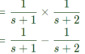
Sol: 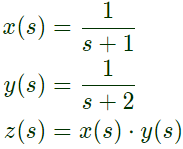

Q25: Given the finite length input x[n] and the corresponding finite length output y[n] of an LTI system as shown below, the impulse response h[n] of the system is (2010)
 (a) h[n] = {1, 0, 0, 1}
(b) h[n] = {1, 0, 1}
(c) h[n] = {1, 1, 1, 1}
(d) h[n] = {1, 1, 1}
Ans: (c)
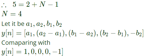
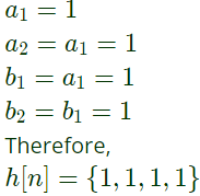
Sol: x[n] = { 1, -1}, M = 2
y[n] = {1, 0, 0, 0, -1}, N1 = 5
Since, output hasnumber of elements
N1 = M + N − 1
where N is number of elements in impulse response h[n].
Q26: The system represented by the input-output relationship  (2010)
(a) Linear and causal
(b) Linear but not causal
(c) Causal but not linear
(d) Neither liner nor causal
Ans: (b)
Sol: Integrator is always a linear system.

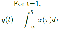 here value at t = 1 depends on future values like at t = 2, 3,... of input x(t).
So, it is a noncausal systems.
Q27: A cascade of three Linear Time Invariant systems is causal and unstable. From this, we conclude that (2009)
(a) each system in the cascade is individually causal and unstable
(b) at least on system is unstable and at least one system is causal
(c) at least one system is causal and all systems are unstable
(d) the majority are unstable and the majority are causal
Ans: (b)
Sol: Since in cascade overall impulse response
h(t) = h1(t)∗h2(t)∗h3(t)
h1(t), h2(t), h3(t) are impulse response of individual systems.
Since, initial point where h(t) is nonzero is t ≥ 0 and since in convolution initial point
= t1 + t2 + t3
where, t1, t2, t3 are initial point of h1(t), h2(t), h3(t) respectively.
So for it to be greater than or equal to zero at least one of them t1, t2 or t3 must be +ve i.e. greater than zero so atleast one of them must be causal. Similarly if one (atleast) of the system become unstable then overall system will become unstable.
Q28: A Linear Time Invariant system with an impulse response h(t) produces output y(t) when input x(t) is applied. When the input x(t - τ) is applied to a system with impulse response h(t - τ), the output will be (2009)
(a) y(t)
(b) y(2(t - τ))
(c) y(t - τ)
(d) y(t - 2 τ)
Ans: (d)
Sol: 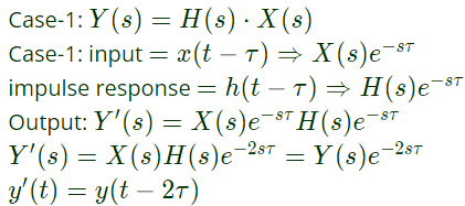
Q29: A system with x(t) and output y(t) is defined by the input-output relation :
 The system will be (2008)
(a) Casual, time-invariant and unstable
(b) Casual, time-invariant and stable
(c) non-casual, time-invariant and unstable
(d) non-casual, time-variant and unstable
Ans: (d)
Sol: First of all we will check for causality,
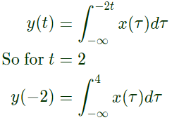 So, output depends on future values of input along with past and present values of input, so system is non-casual.
Let us find output for shifted input x(t − t0)
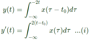 Now, shift the output by t0
then,
 so from eq. (i) and (ii),
 Therefore system is time varient.
Non-causal and time variant is present only in option (D).
Q30: The impulse response of a causal linear time-invariant system is given as h(t). Now consider the following two statements :
Statement (I): Principle of superposition holds
Statement (II): h(t) = 0 for t < 0
Which one of the following statements is correct ? (2008)
(a) Statements (I) is correct and statement (II) is wrong
(b) Statements (II) is correct and statement (I) is wrong
(c) Both Statement (I) and Statement (II) are wrong
(d) Both Statement (I) and Statement (II) are correct
Ans: (d)
Sol: Since, system is casual therefore its impulse response will be zero for t < 0.
So, statement-II is correct.
Since, system is linear, it also satisfies the principle of superposition.
So, both the statements are correct.
Q31: A signal e−αtsin(ωt) is the input to a real Linear Time Invariant system. Given K and ϕ are constants, the output of the system will be of the form Ke−βt sin(vt + ϕ) where (2008)
(a) β need not be equal to α but v equal to ω
(b) v need not be equal to ω but β equal to α
(c) β equal to α and v equal to ω
(d) β need not be equal to α and v need not be equal to ω
Ans: (c)
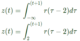
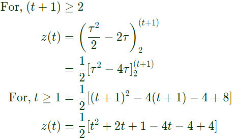
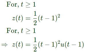
Q32: If u(t), r(t) denote the unit step and unit ramp functions respectively and u(t)*r(t) their convolution, then the function u(t+1)*r(t-2) is given by (2007)
(a) 
(b) 
(c) 
(d) None of the above
Ans: (c)
Sol: 
Q33: Let a signal a1sin(ω1t + ϕ1) be applied to a stable linear time invariant system. Let the corresponding steady state output be represented as a2F(ω2t + ϕ2). Then which of the following statement is true? (2007)
(a) F is not necessarily a "Sine" or "Cosine" function but must be periodic with ω1 = ω2
(b) F must be a "Sine" or "Cosine" function with a1 = a2
(c) F must be a "Sine" function with ω1 = ω2 and ϕ1 = ϕ2
(d) F must be a "Sine" or "Cosine" function with ω1 = ω2
Ans: (d)
Sol:  The effect of linear time invariant systems is best understtod by considering that, at any given input frequency ω1, the output is sinusoidal at same frequency, as the input applied, with amplitude given by output = |H| x input and phase equal to ϕ2 = ϕH + ϕ1, where |H| is the magnitude to the frequency response and ϕH is its phase angle. Both |H| and ϕH are functions of frequency.
Q34: y[n] denotes the output and x[n] denotes the input of a discrete-time system given by the difference equation y[n] - 0.8y[n-1] = x[n]+1.25x[n+1]. Its right-sided impulse response is (2006)
(a) causal
(b) unbounded
(c) periodic
(d) non-negative
Ans: (d)
Sol: From the given difference equation
 For right sided impulse response, h(n) the ROC is ∣Z∣ > 0.8
h[n] = (0.8)nu[n] + 1.25(0.8)n + 1u[n + 1].
h[n] has positive value for any n,
h[n] is non-negative.
It can be verified that h[n] is non-causal, bounded and not periodic
As h(−1) = 1.25, h[n] is non-causal
h[n] ≤ M, M < ∞; h[n] is bounded .
h[n] is not periodic as it is a monotonically decaying sequence.
Q35: x[n] = 0; n < −1, n > 0, 𝑥[−1] = −1, x[0] = 2 is the input and
y[n] = 0; n < −1, n > 2, 𝑦[−1] = −1 = 𝑦[1], 𝑦[0] = 3, 𝑦[2] = −2
is the output of a discrete-time LTI system. The system impulse response h[n] will be (2006)
(a) h[n] = 0; n < 0, n > 2, h[0] = 1, h[1] = h[2] = −1
(b) h[n] = 0; n < −1, n > 1, h[−1] = 1, h[0] = h[1] = 2
(c) h[n] = 0; n < 0, n > 3, h[0] = −1, h[1] = 2, h[2] = 1
(d) h[n] = 0; n < −2, n > 1, h[−2] = h[1] = h[−1] = −h[0] = 3
Ans: (a)
Sol: For finite duration convolution,
x[n] have M terms
h[n] have N terms
then y[n] should have terms (M+N+1)
Here, x[n] = {-1, 2}
y[n] = {-1, 3, -1, -2}
So, h[n] should have only 3 terms and h[n] have value starting from origin or [n = 0] only because y[n] have value start from [n = -1]
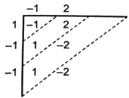 y[n] = {-1, 3, -1, -2}.
Q36: Let s(t) be the step response of a linear system with zero initial conditions; then the response of this system to an input u(t) is (2002)
(a) 
(b) 
(c) 
(d) 
Ans: (b)


 The system is (2012)
 So, system is not time invariant for input xτ = cos(3τ) bounded input
 So, for bounded input, output is not bounded therefore system is not stable.


 (a) h[n] = {1, 0, 0, 1}

 (2010)
 here value at t = 1 depends on future values like at t = 2, 3,... of input x(t).
 The system will be (2008)
 So, output depends on future values of input along with past and present values of input, so system is non-casual.
 Now, shift the output by t0
 so from eq. (i) and (ii),
 Therefore system is time varient.


 The effect of linear time invariant systems is best understtod by considering that, at any given input frequency ω1, the output is sinusoidal at same frequency, as the input applied, with amplitude given by output = |H| x input and phase equal to ϕ2 = ϕH + ϕ1, where |H| is the magnitude to the frequency response and ϕH is its phase angle. Both |H| and ϕH are functions of frequency.
 For right sided impulse response, h(n) the ROC is ∣Z∣ > 0.8
 y[n] = {-1, 3, -1, -2}.


