Q1: To obtain the Boolean function 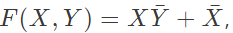 the inputs PQRS in the figure should be (2024)
 (a) 1010
(b) 1110
(c) 0110
(d) 0001
Ans: (b)
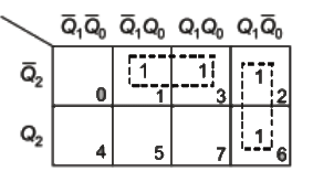
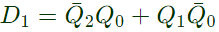
Q2: A counter is constructed with three D flip-flops. The input-output pairs are named (D0, Q0), (D1, Q1) and (D2, Q2), where the subscript 0 denotes the least significant bit. The output sequence is desired to be the Gray-code sequence 000, 001, 011, 010, 110, 111, 101 and 100, repeating periodically. Note that the bits are listed in the Q2 Q1 Q0 format. The combinational logic expression for D1 is (2021)
(a) Q2Q1Q0
(b) 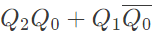
(c) 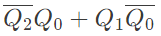
(d) 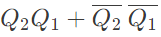
Ans: (c)
Sol: 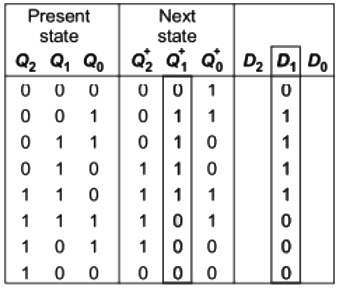
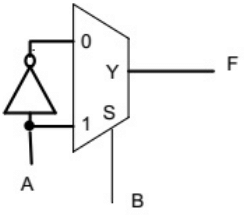
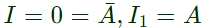
Q3: Consider the following circuit which uses a 2-to-1 multiplexer as shown in the figure below. The Boolean expression for output F in terms of A and B is (SET-1 (2016))
 (a) A ⊕ B
(b) 
(c) A + B
(d) 
Ans: (d)
Sol: In the given multiplexer,
 Select = B
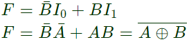
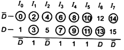
Q4: A Boolean function f(A, B, C, D) = Π(1, 5, 12, 15) is to be implemented using an 8x1 multiplexer (A is MSB). The inputs ABC are connected to the select inputs S2S1S0 of the multiplexer respectively.  Which one of the following options gives the correct inputs to pins 0, 1, 2, 3, 4, 5, 6, 7 in order? (SET-2(2015))
(a) 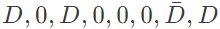
(b) 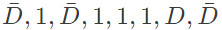
(c) 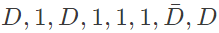
(d) 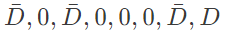
Ans: (b)
Sol: Boolean function f(A, B, C, D) = Π(1, 5, 12, 15) is implemented with 8 x 1 MUX
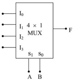
Q5: In the 4 x 1 multiplexer, the output F is given by F = A ⊕ B. Find the required input ' I3 I2 I1 I0'. (SET-1(2015))
 (a) 1010
(b) 0110
(c) 1000
(d) 1110
Ans: (b)
Sol: F = A ⊕ B
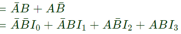 ⇒ I0 = 0, I1 = 1, I2 = 1, i3 = 0
I3 I2 I1 I0 = 0110
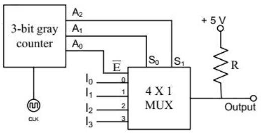
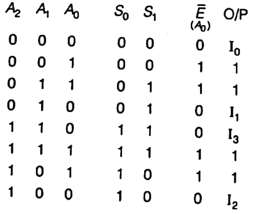
Q6: A 3-bit gray counter is used to control the output of the multiplexer as shown in the figure. The initial state of the counter is 0002. The output is pulled high. The output of the circuit follows the sequence (SET-3 (2014))
 (a) I01, 1, I1, I3, 1, 1, I2
(b) I0, 1, I1, 1, I2, 1, I3, 1
(c) 1, I0, 1, I1, I2, 1, I3, 1
(d) I0, I1, I2, I3, I0, I1, I2, I3
Ans: (a)
Sol: For 
MUX is enabled and output is I0
For 
MUX is disable and output is '1'
similarly, for
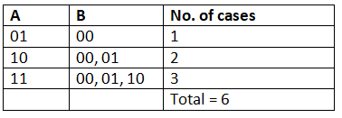
Q7: The output Y of a 2-bit comparator is logic 1 whenever the 2-bit input A is greater than the 2-bit input B. The number of combinations for which the output is logic 1, is (2012)
(a) 4
(b) 6
(c) 8
(d) 10
Ans: (b)
Sol:
Q8: A 3-line to 8-line decoder, with active low outputs, is used to implement a 3-variable Boolean function as shown in the figure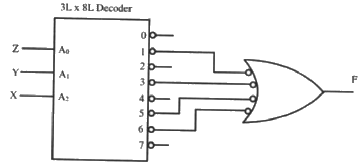 The simplified form of Boolean function F(A, B, C) implemented in 'Product of Sum' form will be (2008)
(a) 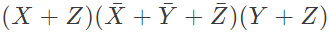
(b) 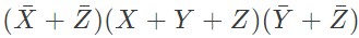
(c) 
(d) 
Ans: (a)
Sol: Let us consider active high input
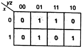 F = Σ(1, 3, 5, 6) = ΠM(0, 2, 4, 7)

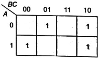
Q9: A (4 × 1) MUX is used to implement a 3-input Boolean function as shown in figure. The Boolean function F(A,B,C) implemented is (2006)
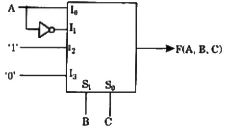 (a) F(A, B, C) = Σ(1, 2, 4, 6)
(b) F(A, B, C) = Σ(1, 2, 6)
(c) F(A, B, C) = Σ(2, 4, 5, 6)
(d) F(A, B, C) = Σ(1, 5, 6)
Ans: (a)
Sol:  = Σ(1, 2, 4, 6)
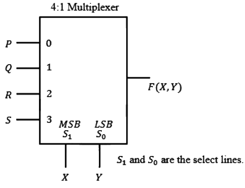
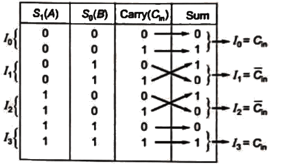
Q10: Figure shows a 4 to 1 MUX to be used to implement the sum S of a 1-bit full adder with input bits P and Q and the carry input Cin. Which of the following combinations of inputs to I0, I1, I2 and I3 of the MUX will realize the sum S ? (2003)
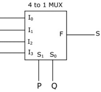 (a)
(a) 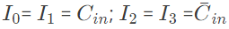
(b) 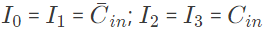
(c) 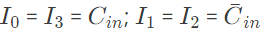
(d) 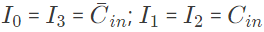
Ans: (c)
Sol: For a 4:1 mux
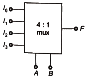

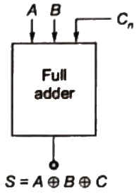 where sum of full adder is = A ⊕ B ⊕ C
Truth table of Full adder
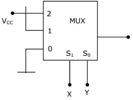
Q11: The output f of the 4-to-1 MUX shown in figure is (2001)
 (a)
(a) 
(b) X + Y
(c) 
(d) 
Ans: (b)
Sol: ∵F = Σmin(1, 2, 3)
∴ 


