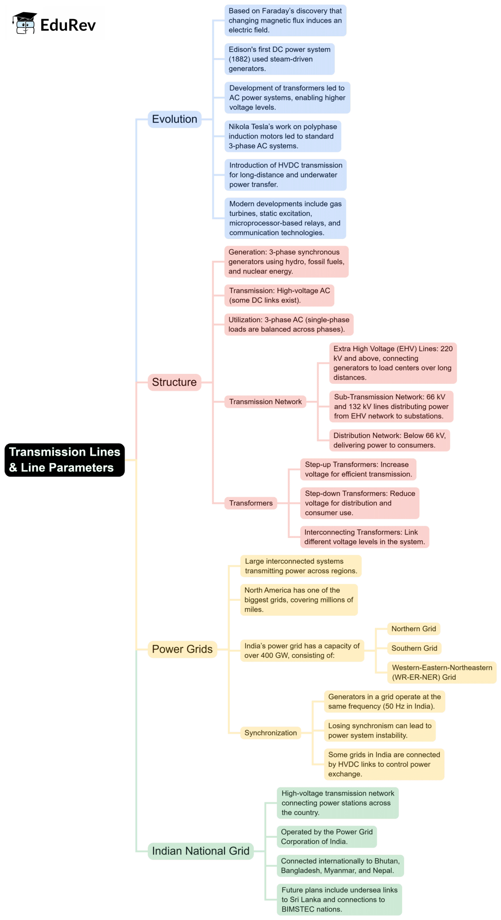
Electrical Engineering (EE) Exam > Electrical Engineering (EE) Notes > Power Systems > Mind Map: Transmission Lines & Line Parameters
Mind Map: Transmission Lines & Line Parameters | Power Systems - Electrical Engineering (EE) PDF Download

The document Mind Map: Transmission Lines & Line Parameters | Power Systems - Electrical Engineering (EE) is a part of the Electrical Engineering (EE) Course Power Systems.
All you need of Electrical Engineering (EE) at this link: Electrical Engineering (EE)
|
30 videos|101 docs|45 tests
|
FAQs on Mind Map: Transmission Lines & Line Parameters - Power Systems - Electrical Engineering (EE)
| 1. What are the primary parameters of transmission lines in electrical engineering? |  |
Ans. The primary parameters of transmission lines include resistance (R), inductance (L), capacitance (C), and conductance (G). These parameters determine the performance of the transmission line, influencing voltage drop, power loss, and signal integrity.
| 2. How do resistance and reactance affect transmission line performance? |  |
Ans. Resistance causes power losses in the form of heat, while reactance (which includes both inductive and capacitive reactance) affects the phase relationship between voltage and current. High resistance can lead to significant energy losses, while reactance can cause voltage drops and distortions in signal transmission.
| 3. What is the significance of the characteristic impedance of a transmission line? |  |
Ans. The characteristic impedance (Z₀) of a transmission line is crucial as it determines how signals propagate along the line. Matching the load impedance to the characteristic impedance minimizes reflections and ensures maximum power transfer, which is essential for efficient system performance.
| 4. What are the different types of transmission lines based on their length and application? |  |
Ans. Transmission lines can be categorized into short, medium, and long lines. Short lines are typically less than 250 km and can be analyzed using lumped parameters. Medium lines, ranging from 250 km to 500 km, require a more detailed analysis considering both lumped and distributed parameters. Long lines, over 500 km, are analyzed using distributed parameters due to significant voltage drop and phase shift.
| 5. How does the skin effect influence the design of transmission lines? |  |
Ans. The skin effect causes alternating current to flow mainly on the surface of conductors, leading to an increase in effective resistance at higher frequencies. This phenomenon must be considered in the design of transmission lines, especially for high-frequency applications, as it can affect efficiency and heat dissipation.
Related Searches


