DC Machines - 1


Introduction
- DC machines are versatile electromechanical energy converters capable of providing high starting torque and rapid acceleration or deceleration.
- They are easily adaptable for applications requiring wide-range speed control and quick reversals of rotation.
- DC machines possess a high degree of operational flexibility and simple control characteristics.
- Typical applications of DC motors include steel and aluminium rolling mills, power shovels, electric elevators and traction (rail) locomotives.
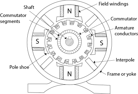
Constructional Features
In a DC machine the field winding is mounted on the stator (stationary part) and the armature winding is mounted on the rotor (rotating part). The machine therefore consists essentially of two main parts: the stator and the rotor.
Stator
 Parts of Stator
Yoke
The yoke (frame) forms the outer structure of the machine.
- On large DC machines the yoke is usually fabricated from steel laminations to reduce eddy-current losses.
- The yoke provides a magnetic path for part of the pole flux and gives mechanical support to the whole machine.
Field poles
Each pole comprises a pole core and a pole shoe.
- The pole core may be of thicker steel but pole shoes are laminated and fixed to the core to reduce losses and provide a wide pole face.
- Field poles carry the field winding (exciting winding) which produces the main flux under the pole faces.
Note: In modern DC machines intended for drive by power-electronic converters, most stator parts (yoke, pole cores, pole shoes) are laminated to reduce eddy-current losses.
Field winding
The field winding is wound on the pole cores and is usually copper insulated conductor. Different DC machine types use different winding styles:
- In a series DC machine, a small number of turns of large cross-section conductor is used because the full armature current flows through the field winding.
- In a shunt DC machine, a large number of turns of small cross-section conductor is used since only the shunt current flows through the field winding.
- In a compound DC machine both shunt and series field windings are present to combine properties of both types.
Interpoles (Commutating poles)
- Interpoles are small poles fitted to the yoke midway between the main poles.
- They are tapered to provide sufficient sectional area at the root to avoid magnetic saturation and are connected in series with the armature so that their magnetomotive force is proportional to armature current.
Remember: Interpoles are used to improve voltage commutation (reduce sparking at brushes during reversal of coil currents).
Compensating winding
- Compensating windings are used to reduce the adverse effects of armature reaction in large DC machines.
- They are placed in slots cut in the pole faces and connected in series with the armature circuit so their mmf opposes the armature mmf in the pole faces.
Brushes
- Brushes provide the electrical contact between the stationary external circuit and the rotating commutator segments.
- Small DC machines commonly use carbon brushes; electro-graphite is used widely for larger machines for improved wear characteristics and current carrying capability.
- Brushes are retained in holders and held against the commutator by springs to maintain low contact resistance and reliable electrical contact.
Rotor (Armature)
Armature core
- The armature core is built up from thin silicon-steel laminations (typically 0.35-0.50 mm) to reduce eddy-current losses.
- The core houses the armature slots and windings and provides a low-reluctance path for the magnetic flux returning from pole to pole.
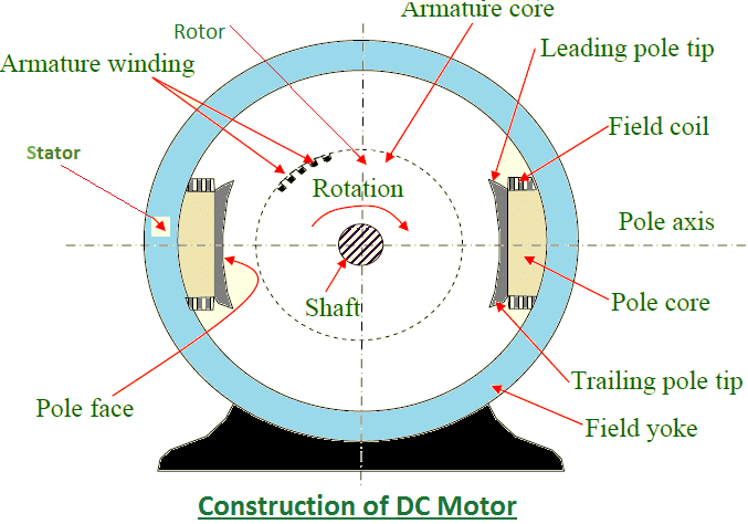
Armature winding
- The armature winding is made of insulated copper conductors arranged as a large number of coils placed in the slots of the armature core.
- Coils are connected in series and/or parallel depending on the required voltage and current characteristics.
- Two principal armature winding types are used: lap winding and wave winding. Lap winding gives more parallel paths (a = number of poles) and is suited to high current, low voltage machines. Wave winding provides a small number of parallel paths (a = 2) and is suited to high voltage, lower current machines.
Commutator
- The commutator is assembled from wedge-shaped copper segments insulated from one another and from the shaft by mica or other insulation to withstand centrifugal forces.
- Its two main functions are:
- to convert the alternating emf generated in each armature coil into a unidirectional (dc) external terminal voltage, and
- to keep the resultant armature mmf stationary in space (as required for steady torque production).
Shaft and bearings
- The armature core, commutator hub and rotor bearings are mounted on the shaft which transmits mechanical power to or from the machine.
- End covers (bearing housings) are connected to the yoke and support the bearings and shaft at each end.
Try yourself: Which of the following statements is true about DC machines?
Generated E.M.F. in DC Machines
- Consider a two-pole DC machine with an N-turn coil placed under the air gap. As the armature rotates in the field, an alternating emf is induced in the coil sides which is converted to a unidirectional quantity by the commutator.
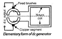
- The commutator consists of copper segments insulated from each other; the two ends of each armature coil are connected to appropriate commutator segments and stationary brushes make sliding contact with the segments under spring pressure.
- The commutator converts the alternating emf induced in each coil into a direct or unidirectional voltage available at the brushes, and also preserves the spatial stationarity of the armature mmf required for steady torque.
The distribution of flux density around the air gap periphery (flux-density wave) is typically represented by its fundamental sine component when deriving induced emf. The rotor is assumed to rotate at an electrical angular speed ωr (radians per second).
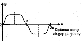 Variation of Field density along the air gap periphery

- The instantaneous emf induced in a coil side depends on its velocity relative to the magnetic flux and on the local flux density; when the coil side moves parallel to the flux lines the emf is zero; when it cuts the flux most rapidly the induced emf is maximum.
- The polarity of emf in the coil sides follows from the right-hand rule and the commutator ensures that brushes see a unidirectional terminal voltage as the coil rotates through different flux zones.
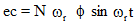
Average (dc) value of the emf from a single coil or conductor can be derived by integrating the sinusoidal induced emf over the commutation interval and accounting for the number of conductors and parallel paths.

Here ωr is the armature electrical angular speed in radians per second.
- If Z is the total number of armature conductors and they are arranged in a parallel paths, then the number of conductors in each parallel path = Z / a.
- Average emf per conductor (for one electrical cycle) may be expressed in terms of pole flux Φ, speed and number of poles P; a commonly used compact form for the generated terminal voltage is given below.
- The terminal (output) voltage between brushes is:
Ea = Ka Φ ωm - Here ωm is the mechanical angular speed (rad s⁻¹) related to speed n (rev s⁻¹) by ωm = 2π n.
- The constant Ka depends on the armature winding design and is given by:
Ka = Z P / (2π a) - For a lap winding the number of parallel paths a = P (number of poles).
- For a wave winding the number of parallel paths a = 2 regardless of the number of poles.
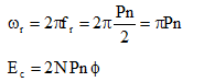
Commutation Process
Commutation is the process by which the current in an armature coil is reversed as the coil moves under a brush and across adjacent commutator segments. Proper commutation is essential to avoid sparking at brushes and to ensure correct current flow in the external circuit.
- As a coil approaches a brush it carries current Ic in one direction; after crossing the brush the coil current is reversed (-Ic) when the coil connects to the next commutator segment.
- During commutation the coil undergoing reversal is effectively short-circuited by the brush and commutator until its current reverses.
- The number of coils simultaneously undergoing commutation depends on the number of brushes and the pole and winding arrangement.
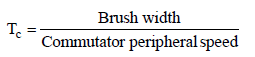
- The time required for the coil current to change from +Ic to -Ic is called the commutation period Tc.
- The current in the local short-circuited circuit during commutation is influenced by:
- the contact resistance between copper and carbon (brush contact resistance),
- the resistance of the coil being commutated,
- emfs induced in the commutated (short-circuited) coil due to changing flux linkage, and
- emf induced due to rotation of the coil in any cross (armature) flux present in the interpolar zone.
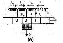
- Consider an armature coil connected to adjacent commutator bars (as in a lap winding). Assume that the brush width equals the bar width and mica insulation between bars is negligible for the geometric argument.
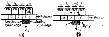
- When a brush contacts two adjacent bars equally each bar supplies half the brush current and the coil undergoing commutation carries little or no net current.
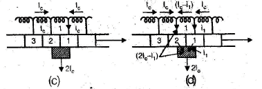
- As the rotor turns further, contact area with the older bar reduces and with the newer bar increases; currents redistribute and the coil current reverses smoothly subject to the circuit impedances and induced emfs.

- Proper commutation requires that the net induced emf in the short-circuited coil during reversal be negligible so that current change is determined by resistive time-constants and not by large induced voltages which cause sparking.
- Features that improve commutation include interpoles, compensating windings, brush shifting (to the neutral zone) and using brushes and commutator materials with suitable contact resistance.
Interpoles (Commutating poles) - further details
Interpoles are narrow poles placed midway between the main poles and fitted to the machine yoke. They are often called commutating poles or compoles.
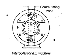
- Interpoles are connected in series with the armature so that the interpole mmf is proportional to armature current and therefore appropriate for the instantaneous commutation demand.
- For a generator the interpole polarity in the direction of rotation is the same as that of the main pole head ahead of it; for a motor the interpole polarity must be the same as that of the main pole behind it.
- The interpole flux neutralises the armature cross-flux in the commutating zone and can be adjusted to produce a rotational emf in the commutated coil that opposes the reactance (inductive) voltage produced by changing current. If the interpole-produced rotational emf equals the reactance emf, then com mutation can be sparkless.
- Interpoles are designed to provide mmf greater than the armature mmf in the commutating zone to ensure effective neutralisation and improved commutation.
Try yourself: In a DC machine, what is the main function of a commutator?
MMF and Flux-Density Waveforms
Under each pole the current distribution due to field and armature currents can be represented by current sheets or by space-harmonic waveforms. When deriving induced emf and discussing armature reaction it is common to consider only the fundamental sine component of the flux density wave in the air gap.
Armature reaction
The mmf produced by currents in the armature winding (armature mmf) affects the main field flux in two principal ways:
- It reduces the effective main flux per pole (demagnetising effect), and
- It distorts the main field flux distribution across the air gap (cross-magnetising or distorting effect).
- Reduction of the main flux per pole reduces generated voltage and torque capability; distortion of the flux distribution affects the conditions for successful commutation and can cause sparking if not corrected.
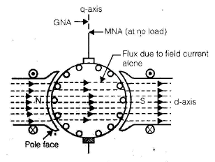
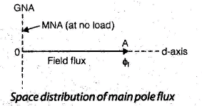
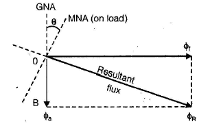
- At no load (no armature current) the main flux follows the path determined by the field poles alone. Under load, armature currents set up an additional flux (armature flux) which is cross-magnetising relative to the main field.
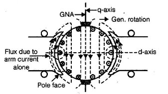
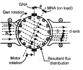
- The armature flux aids the main field flux at some parts of a pole face (e.g. at one tip) and opposes it at other parts. The net result is usually a reduction in average flux per pole (demagnetising effect) and a distortion of the flux density waveform under the pole.
- Because of the distortion, the magnetic neutral axis (MNA) shifts relative to the geometric neutral axis (GNA). For a generator the MNA shifts in the direction of rotation; for a motor it shifts against the direction of rotation. The shift magnitude depends on armature current.
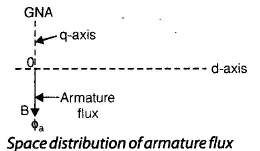
- The armature mmf distribution in space is often approximated by a triangular or sinusoidal wave with its peak along the quadrature (brush) axis, i.e. 90° away from the main field axis. The interaction of this armature mmf with the main field is termed armature reaction.
Try yourself: Which of the following statements is true regarding the effects of armature-reaction in a DC machine?
Summary: This chapter has described the constructional elements of DC machines (stator and rotor details), the principle of generated emf and the role of the commutator, the commutation process and means of improving it (interpoles, compensating winding), and the effect of armature mmf on main flux (armature reaction). The expressions for generated emf in terms of flux, machine constants and speed have been presented together with the practical winding conventions (lap and wave) that determine the number of parallel paths and current distribution.
FAQs on DC Machines - 1
| 1. What is the basic principle of operation in a DC machine? |  |
| 2. How do commutators and brushes work together in DC machines? | |
| 3. What's the difference between a DC generator and DC motor, and how do they switch functions? | |
| 4. Why does back EMF matter so much in DC motor performance? | |
| 5. What are the main losses in DC machines and how do they affect efficiency? | |


 | Explore Courses for Electrical Engineering (EE) exam |
 | Get EduRev Notes directly in your Google search |