DC Machines- 2 | Electrical Engineering SSC JE (Technical) - Electrical Engineering (EE) PDF Download
COMPENSATING WINDING:
- To eliminate the effect of armature reaction, compensating winding is used.
- The compensating winding provides the compensation to the armature flux which are lying under pole shoe.
- The trouble of flash over which is due to the distortion of flux-density wave under the pole shoes or due to the rapidly changing loads, can be effectively overcome by neutralizing or compensating the armature mmf under the pole faces.
- The armature and compensating winding are connected in series so that their mmf's are proportional to the same current.
- In order that their mmfs oppose each other, the direction of currents in the compensating winding must be opposite to that in the armature winding just below the pole faces.
- In the interpolar region, the compensating winding mmf and interpolar winding mmf, both oppose armature mmf. The resultant of these three mmfs in the commutating zone should not be zero, from the view point of cancelling the reactance emf.
- Under the pole faces, compensating winding mmf neutralizes the armature winding mmf. Therefore the resultant flux density waveform under the pole faces is seen to be independent of load current and is of the same waveform as produced by the main field winding have full control over the air-gap flux.
- By using compensating winding, armature flux linkages are reduced, thus armature inductor effect is also reduced.
- The compensating winding mmf neutralizes the armature mmf only under the main pre-faces, the compensating winding mmf per pole ATc.


- The compensating winding conductors Zcw.

Summarizing, the methods of improving commutation in d.c. machines are as follows :
- By increasing the brush contact resistance. This causes more voltage drop at the brush-bar contacts as compared with the reactance voltage and the commutation is improved. This method called resistance commutation is employed in fractional kW d.c. machines.
- By shifting the brushes forward in a generator or backward in motor. This method was employed for commutation improvement before the invention of interpoles.
- By providing interpoles. This method is employed in almost all sizes of d.c. machines, except in very small d.c. machines.
- By providing compensating winding. Since the d.c. machines with compensating winding are more expensive, these are used in those d.c. machines only which have to perform server duty cycles in industry.
CIRCUIT MODEL OF DC MACHINES:
- In dc machines, all parallel paths in the armature are symmetrical. Each path has a generated emf Ea and a resistance rp.
- For generator, electromagnetic torque Te is opposite to the rotor rotation.
- This is essential for the conversion of energy from mechanical to electrical.
- For motor, the electromagnetic torque Te is in the direction of rotor rotation.
Generating Mode
- When armature current Ia is in the direction of generated emf Ea, dc machine operates in the generating mode.
- Shaft power input = Ea Ia + no-load rotational loss and Vt = Ea – Ia ra
Where Vt = Armature terminal voltage, V
Ia = Armature current, A
ra = Armature circuit resistance, ohms.
Brush contact drop is usually taken as constant at 1 or 2 V.
- It is dependent of armature current.
- Electrical power output = Electromagnetic power
– Ohmic losses
– Brush loss
Motoring Mode
- When armature current Ia flows in opposition to generated emf Ea as in Figure (b), dc machine operates in motoring mode.
- Shaft power output = Ea Ia – no load rotational loss and Vt = Ea + Iara
- Electrical power input = Electromagnetic power + Ohmic losses + Brush contact loss
- For assumed anti clockwise rotation, S and N poles indicated on the rotor in Figure (a) must be created by armature currents. This magnetic polarity demands the current direction in the conductors to be indicated by crosses under S pole and by dots under N pole.
- This shows that generated emfs and current in a conductor are in the same direction for a dc machine working as a generator.
- These currents establish N and S poles on the rotor and their interaction with the stator. N and S poles results in clockwise rotation of armature. With the armature rotation, the conductors cut the same flux that gives rise to motor torque. This flux cutting action thus causes the generation of emf in the very same conductors that experience motor action.
- Generated emfs are in directions opposite to the flow of conductor current.
- In a generator, Ea > Vt and in a motor, Ea < Vt.
- When dc machine is working as a motor, the generated emf Ea is often called the counter emf or back emf.
Working function of D.C. Machines:
- D.C. machines can operate as generating mode or motoring mode.
Generating Model:
- When armature current Ia is in the direction of generated emf Ea, d.c. machine operates in the generating mode.
- From figure of a generator, electro-magnetic torque Te is opposite to the rotor rotation. i.e. Te is opposite to the rotor rotation i.e. Te opposes the prime-mover torque. This is essential for the conversion of energy from mechanical to electrical. This torque Te may be called counter-torque in a d.c. generator.
Vt = Ea – Ia ra – Vb
Vt = terminal voltage, V
Ia = armature current, I
ra = armature resistance, ohms,
Vb = brush contact voltage drop
If Ia is multiplied to the equation
The, Vt Ia = Ea Ia – Ia2 - ra - Vb Ia
Electrical power = Electromagnetic
out power
– ohmic loss –Brush contact loss
Motoring Mode
- In a d.c. machine, when armature current Ia flows in opposition to generated emf Ea the machine operates in motoring mode.
For d.c. motor.
Vt = Ea + Ia ra + Vb
Ia is multiplied to equation
Vt Ia = Ea Ia + Ia2 - ra - Va Ia
Electrical Power = Electromagnetic power + ohmic losses + Brush contact loss
Input
- In d.c. machines, the electrical power developed is equal to mechanical power developed.
- Electromagnetic torque
Induced emf
ω = 2πN


Ka is constant.
Total developed torque or electromagnetic torque

MAGNETISATION CURVE
The magnetisation curve is the relationship between air-gap flux Ø and the field winding Mmf or field winding current.
- For constant speed ωm, the armature generated emf Ea at no-load, is proportional to air-gap flux Ø only.
- This curve is also called no-load or open circuit characteristic, or saturation curve.
- The magnetisation cure for any other speed, can be obtained by equation.
The dashed straight line, tangent to the straight line portion of magnetization curve at speed ωm , is called air-gap line.
OPERATING CHARACTERISTICS
DC Generators
- More important characteristics of dc generators are four and these are given below :
No-load characteristic
Ea = f (If) with speed n = constant. This characteristic is also called saturation curve, open-circuit characteristic, magnetization curve or no-load magnetization curve.
Load characteristic
Vt = f (If) with both Ia and n constant. This characteristic is also called magnetization curve.
External characteristic
Vt = f (IL) with both If and n constant.
Armature characteristic or regulation curve
If = f (Ia) with both Vt and n constant
- The shape of these characteristics depends upon the method of exciting the field winding.
Remember :
- All the dc generator characteristics listed above, speed is held constant by the prim-mover
- These are generally four types which are given below. These are different for different types of d.c. generator.
Separately-Excited Generator
These generators are used when a wide range of output voltage is required.
No-load Characteristic
- This characteristic gives the variation of armature generated e.m.f. Ea with field current If, for zero armature current and constant speed.
- The magnetization curve for low values of If is a straight line, because the entire field mmf is almost spent in forcing the flux through the air gap and the mmf required by the iron is almost negligible.
- With increased values of If and above a certain value of field flux, saturation sets in and mmf required by the iron increases more rapidly than the flux.
Load characteristic
- Run the armature at constant rated speed and close the switch S.
- Adjust the field current till Ia is equal to rated armature current (or any other specified current) and take the instrument readings.
- Vary the load an field currents in such a manner that armature current Ia and speed n remain constant, but terminal voltage Vt changes
External characteristics
- The generator is run at rated speed and its field winding is excited to give rated terminal voltage at no load. Now close the switch S, vary load resistance in steps and for each step, note terminal voltage and load current. A typical external characteristic is shown in figure (b), by curve 1.
- The decrease in terminal voltage drops caused by armature reaction and armature circuit resistance.
- The internal characteristic gives the variation of armature no-load generated emf Ea minus the minus the voltage drop due to armature reaction, with load current IL or Ia.
- Internal characteristic gives the relationship between internally generated emf and the load current for constant speed and field current.
- OA is the no-load terminal voltage Ea.
Armature Characteristic or Voltage Regulation
- At no load, the field current is adjusted to give rated terminal voltage of the machine, figure (a). The load current is now increased in steps and at each step, the field current is adjusted to keep the terminal voltage constant. The regulation curve is then plotted as shown in figure. In the beginning, the curve is almost a straight line and as the saturation sets in, it bends upwards.
- This characteristic can be employed for calculating the number of series turns for any degree of compound in dc compound machines
Shunt Generators
Remember :
- The load current must be well below the maximum current for avoiding large dips in the terminal voltage.
No-load Characteristics
- If the field winding circuit of the shunt generator is disconnected from the armature circuit and separately excited, then the no-load characteristic with separate excitation will not difference from that obtained with shunt excitation.
- This is due to the fact that small amount of current (1 to 3% of rated current) flowing in the armature of the shunt generator, has negligible effect on the main flux.
Load Characteristic
- The load characteristics obtained both for separate and shunt excitation, are the same.
- The slight difference is due to the different armature currents, Ia = IL + If for shunt generator and Ia = IL for separately - excited generator.
External Characteristic
- The generator is run at rated speed and the field current is adjusted to give rated volt age (or any other suitable voltage) at no-load. Switch S is closed, the load is gradually increased in steps and the instrument readings at each step are recorded. A plot of the terminal voltage Vt and load current IL, with present value of field current and speed, gives the external characteristic curve 1 in figure.
- The drop in terminal voltage is due to (a) armature resistance drop Ia ra (b) reduction in main flux due to armature reaction and (c) further reduction in field current It.
- A reduction in field current causes the flux and therefore the generated emf to decrease. Thus the terminal voltage of the generator for a given load current, will be lower when shunt excited than when current, will be lower when shunt excited than when separately excited, provided no load voltage is same in both the cases.
- Over the normal operating range, the internal characteristic given by curve 2, can be obtained by adding Ia ra drop to the ordinates of external characteristic.
Armature Characteristic
- Shunt generator armature characteristic is obtained by running it as a separately excited generator.
Voltage Building in Shunt Generator
- Consider an unloaded shunt generator as illustrated in figure
- The straight line Oa is the graphical plot of Ohm’s for the field circuit. In other words, the slope of the line Oa, drawn through origin, represents the field resistance.
- When the armature is driven at a speed flow which the magnetization curve is given, the residual pole flux generates a small voltage Oc, with switch S open, i.e. with zero field current. when switch S is closed, residual flux voltage Oc produces a small field current. If the flux produced by this small field current, adds to the residual flux, still larger voltages are generated.
- Residual flux voltage Oc is shown to produce a small field current equal to Od, which in turn raises the generated voltage to de. This voltage de, raises the field current to Of, which further raises the generated emf to fg, now emf fg raises the field current to Oh, which in turn increases the generated emf to hj and so on, till stable point n is reached
- If shunt field resistance is increased to OA (slope of the field resistance line increased) then the field resistance line and the magnetization curve intersect at point q, therefore, the voltage will not build up further than point q.
- Field resistance line OB is tangent to the magnetization curve and the field resistance represented by line OB is called the critical field resistance at a given speed.
- If shunt field resistance is more than the critical field resistance such as given by line OA, there will be no voltage build up.
- Critical speed is the speed at which the dc shunt generator just fails to build no external resistance in field circuit.
Failure to Build-up
- If the self-excited generators fail to build-up the voltage at no-load, it may be due to any one of the following reasons.
No-residual Magnetism
- The voltage build up process can start only if there is residual magnetism in the magnetic circuit of the generator.
Field Connections Reversed
- If the field-connections are incorrect, the flux produced by small field current opposes the residual flux and the generated voltage decreases to zero.
High Field Circuit Resistance
- In case the field resistance is more than the critical field resistance, voltage will not build up. Speed Less than Critical Speed
- The armature speed being less than the critical speed.
Series Generator
These generators are used mainly as series boosters connected in the line, to neutralise the effect of line ohmic drop.
No load Characteristic
- In a series generator, the armature winding, field winding and load resistance are connected in series, therefore the field current is equal to the armature or load current.
- The no-load magnetization curve can only be obtained by separately exciting its field from a low voltage source.
- The magnetization curve at one speed for a series generator is illustrated by curve 1 in figure
Load Characteristic (load magnetization curve)
- This characteristic also, can only be obtained by separately exciting the series field winding. The shape of this characteristic is identical with that of the separately excited generator.
External Characteristic
- With the switch S open, the small voltage due to residual flux will be indicated by the voltmeter. When the switch S is closed, field current equal to the load current, starts flowing. If the current in the series field produces a flux aiding the residual flux, the generator will build up voltage till point C is reached.
- The field resistance line OC depends on the total resistance in the series circuit i.e., the slope of line OC is determined by the sum of armature circuit resistance, series field resistance and load resistance.
Compound Generator
- Cumulatively compounded generators are more common because these can furnish almost constant voltage from no load to full load.
No Load Characteristic
- Same current flows through the series field and shunt field turns in case of a long-shunt compound generator.
- Since the number of series field turns is far less than that of the shunt field turns, the effect of series field mmf may be neglected in comparison with the shunt field mmf at no load.
- For a short-shunt compound generator, series field carries no current when obtaining its no load characteristic. Thus the no load characteristic of a longshunt or shot shunt compound generator is the same as if it were a shunt generator.
External Characteristic
- The external characteristics of a compound generator are shown in figure below :
- In a cumulatively compounded generator, with the increase of load current, the series field flux aids the shunt field flux.
- Depending upon the number of series field turns, the cumulatively compounded generator may be undercompounded (terminal voltage falls with increase of load), level or flat-compounded (terminal voltage remains practically constant with increase in load) or over-compounded (terminal voltage rises with increase in load).
- In a differentially compounded generator, with the increase in load, the series-field flux opposes the shuntfield flux and consequently the terminal voltage falls more rapidly.
- Differentially compounded generators are not damaged by short circuit. In view of this, these generators my be used for welding purposes.
- The degree of compounding can be controlled by connecting a suitable low resistance called diverter, in parallel with the series field winding.
Observations :
- For series generator, curve 1, the terminal voltage rises rapidly with load current. At overloads, terminal voltage beings to decrease owing to saturation, armature reaction etc.
- For cumulative over-compounded generator, curve 2, no-load voltage is less than Vtr.
- For level, or flat compounded generator, curve 3, the no-load voltage and full-load voltages are equal. However, terminal voltage at light load is more than Vtr but at overloads it falls below Vtr.
- For cumulative under-compounded generator, curve 4, no-load voltage is more than Vtr.
- For both separately-excited (curve 5) and shunt (curve 6) generators, Vtr is less than no-load voltage. Voltage variation from no-load to full load is less in separately-excited generator than in a shunt generator.
- For differential compounded generator, no load voltage is much higher than Vtr.
OPERATING CHARACTERISTICS
DC Motors
- The following are the three important operating characteristics of dc motors.
- Speed-armature current characteristic
- Torque-armature current characteristic and
- Speed-torque characteristic.
DC Shunt Motor
- For constant supply voltage, the field current is constant. At small values of armature current the demagnetizing effect of armature current the demagnetizing effect of armature reaction is almost negligible and therefore the air gap flux is unaffected.For larger value of armature (or load) currents, the demagnetizing effect of armature reaction, decreases the air gap flux slightly.
Speed-Current Characteristic
- For constant supply voltage V1 and constant field current If, the motor speed is affected by Ia ra drop and demagnetizing effect of armature reaction. With the increase of Ia, the demagnetizing effect of armature reaction increases which reduces the field flux – therefore the motor speed tends to increase.
- The speed of dc shunt motor with increase of Ia drops only slightly from its no-load speed ωmo. Since Ia at no-load is negligibly small, the shunt motor no-load speed wmo is given by
Torque-Current Characteristic
- Te = KaØ La
- The torque would increase linearly with armature current Ia. However, for larger Ia, the flux decreases due to the demagnetizing effect of armature reaction.
Speed-Torque Characteristic
- Also called the mechanical characteristic.
- For larger Te, larger Ia is required and this has the effect of reducing the air gap flux f, due to saturation and armature reaction.
- With increase of Te, Ø is reduced, Te/Ø2 increases at a faster ate and the speed drops more rapidly with the increase of torque.
- If effect of AR is neglected, then (Ka Ø )2 in equation remains constant. As a result, the speed drop with Te is slow.
DC Series Motor
Speed-Current Characteristic
- If saturation and armature reaction are neglected, the main flux f is directly proportional to armature current Ia.
or
or
- The speed-current characteristic of a series motor is a hyperbola.
- Including saturation and armature reaction.
- At increased values of Ia, the flux Ø should increase with Ia, but due to the demagnetizing effect of armature reaction and saturation, the air gap flux Ø tends to remain approximately constant.
- At no load, the armature current is very small, because the power input to motor has to overcome the no load losses only.
- The no load speed of the series motor becomes dangerously high due to small no load current. In view of this, the series motor must always start and operate under load mechanically coupled with it.
Torque-Current Characteristic
- With saturation and armature reaction neglected,
- The torque is proportional to the square of Ia and, therefore, torque-current characteristic is a parabola. But for larger Ia, the net flux tends to remain approximately constant.
- Consequently the torque-current characteristic approaches a straight line for larger values of Ia.
Speed-Torque Characteristic
- If saturation and armature reaction are neglected
- With negligible saturation and armature reaction, the speed-torque characteristic is a hyperbola.
- With saturation and armature reaction included, large torques require large currents and these large currents tend to make air gap flux f constant. This has the effect of making Te approximately proportional to Ia (i.e. Te = KaIa).
- For a series motor, the speed drop at increased load torques is almost negligible.
DC Cumulative Compound Motor
- A differential compound motor is rarely used.
- The performance characteristics of cumulative compound motor are mainly described.
Speed-Current Characteristic
- For a long-shunt compound motor
Vt = Ea + Ia (ra + rs) and
Where
Øsh and Øse are respectively the fluxes created by shunt and series field windings
- With increase in la, the speed drops at a faster rate in cumulative compound motor than in a shunt motor.
- Here no-load speed is assumed to be the same. For comparison purposes.
Speed-Torque Characteristic
- With increase in motor torque Te, armature current rises, with this series-field flux Øse rises.
- The speed-torque characteristic in a cumulative compound motor is more dropping than in a dc shunt motor.
STARTING OF D.C. MOTORS
- The primary function of a starter circuit is during the starting and accelerating time of the motor.
- Due to heavy inrush of starting current taken by the motor may result in.
- Detrimental sparking at the commutation.
- Damage to the armature winding and deterioration of the insulation due to over heating.
- High starting torque and quick accelerationwhich may damage the rotating parts ot the motor and the load.
- Large dips in the supply voltage.
- In order to limit starting current starters are necessary for suitable operation of d.c. machines.
- To limit the starting current, an external resistance should be inserted into armature circuit, which is removed gradually as motor fixe-up the speed. On the basis of these ideas, two type of starters are used. Three Point Starter
- A three point starter with its electrical connection and protective features is shown below.
- Here three terminals (L, A, F) are available from the starter therefore it is called a three-point starter. where L(line), A(Armature) and field (F) must be connected to supply terminal, motor armature terminal and shunt field terminal respectively.
Operation
- When the motor is at rest starter handle H is kept in the off position by strong spiral spring.
- For starting the motor, the handle is rotated to connected with stud 1, as soon as handl H touches stud 1, the shunt field and holding coil HC get connected in series across the supply, whereas the armature gets connected in series with the entire starting resistance.
- Since the current begins to flow in both the field and armature windings, the motor starts rotating.
- After the armature has picked up sufficient speed, the handle H is moved to stud 2, thereby cutting out the resistance between stud 1 to stud 2.
Disadvantage
- Three-point starter can not be used where wide range of speed control by shunt field control (or field weakening method) is required.
- In case of a three-point starter, the field circuit and the hold coil are in series. If speeds above the normal are to be obtained, the field current must be reduced. At a certain value of reduced field current (therefore, increased motor speed), the electromagnetic pull of the holding coil may become less than the spring force. In such a case, the starter handle returns to the OFF position and the motor stops. Thus a three-point starter can not be used where wide range of speed control by shunt field control (or field weakening method) is required. This undesirable feature can be overcome in four-points starters.
- Here two important magnetic coils are used :
- Holding magnet coil or HC which is connected with field winding. The coil HC is also called no-voltage release or low voltage release is acting as protective device.
- Protective device OR, known as the overload release is provided in series with the armature circuit.
- The disadvantage of three-point starter can be overcome in four-point starter.
Four Point Starter
- Four terminals (L, L, F, A) are available in this starter. Everything is same as three point starter only one extra line terminal with extra resister R is connected with point a of the HC coil.
- The function of resistance R is to prevent short circuit of the supply mains, in the case the overload release OR operates. When HC gets short circulated by OR, the current through R is limited by its own resistance and the starting resistance.
- Now it permits wide speed control by field rheostats inserted in field current.
Note:
- Both are starters used in d.c. shunt or d.c. compound motor.
- Starters of series motor are also two type :
- no-volt release type of starter.
- no-load release type of starter.
Armature Resistance Control
- If external resistance Rg is inserted in series with armature resistance. By varying the external resistance Rg1 the speed is controlled. If Rg3 > Rg2 > Rg1 then speed is reduced from no-load speed as shown in figure

At no-load, Ia = 0, then no-load speed is
No = V/KnØ
- Using armature resistance control, speed can be control only below base speed. As flux remain constant at a constant current, say at rated current torque can be maintain constant, when speed is control. This is known as constant torque drive.
∴ Power = Torque × Speed
P = TN
if constant torque drive
then, for constant power drive
P = T × N
If speed is low then torque is high for constant power and when speed is high then torque is low. Hyperbolic characteristic.
Advantage
- This method controls speeds below base speed (rated speed) down to creeping speeds of only a few r.p.m., are easily obtainable. But at reduced speeds a considerable waste of energy. So this method is economically viable where only short time slow down are required.
Disadvantage
- Poor speed regulation with fixed controller resistance Rg in the armature circuit.
- Lower efficiency and operational cost is higher at reduced speed.
Field Flux Control
- Field current,

- Here, external resistance is inserted with field winding in series by varying external resistance Rext, field flux. We know very well that N ∝ 1/Ø
- The speed control is possible only above base speed. Above the base speed due to flux weakening higher current required to be drawn to maintain constant torque generally motor will not permitted to run beyond its rated current, so current is kept constant, hence torque will reduced. It means only constant power drive is applicable in this controlling scheme TN = constant.
Speed control by varying the armature terminal voltage
This is obtained by :
- Ward leonard system
- Controlled rectifiers
- Series-parallel armature control
Word-Leonard System
- In this system M is the main d.c. motor whose speed is to be controlled and G is the separately excited generator driven by a three-phase driving motor (usually an induction motor).
- Motor speed control is obtained nearly by changing the generator field current.
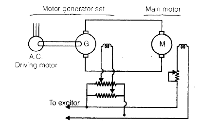
- In order to achieve wider speed control range speeds below base speed are obtained by armature voltage control and above base speed, by field flux control. For better utility of motor M, its armature current Ia is maintained equal to its rated current during its speed control.
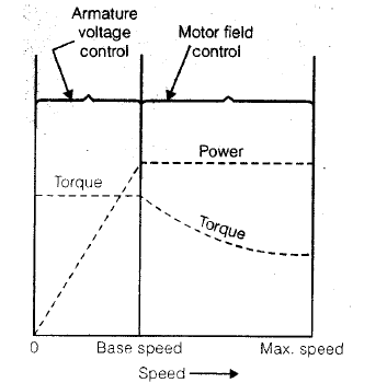
- Below base speed, constant torque drive, armature voltage control is applicable for suitable controlling. When both types of speed controls are employed, the overall speed range is 40 : 1.
Advantage
- The advantages of ward-leonard system of speed control are as follows :
- Its simplicity, wide range and smooth speed control.
- Speed regulation is quite good.
- Control operations is not costly because its field circuits are low-power circuits.
Efficiency at low speeds is higher.
Disadvantage
Higher initial cost, because three machines having rating equal to the full load output are required.
TESTING OF D.C. MACHINES
- Machines are tested for finding out losses, efficiency and temperature rise. Direct loading tests may be performed on small machines. For large shunt machines, indirect machines are used. Swinburne’s test and Hopkinson’s test are mostly used in practice.
Swinburne’s Method
- This is the no-load test, it can not be performed on a d.c. series motor.
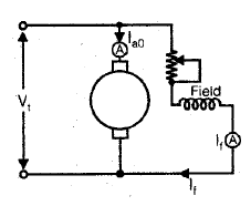
- In this method, the machine, whether it is a motor or a generator is run as no-load shunt motor at rated speed and rated terminal voltage Vt.
If
If = Field current
Ia0 = no-load armature current
The power absorbed by the armature
Vt Iao = No-load rotational losses

shunt field loss = Vt If
shunt field loss = VtIf
Let IL is the load current,
Then for generator efficiency
Armature current Ia = IL + If
Armature circuit loss =Ia2 ra
Shunt field loss =VtIf
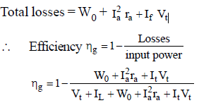
For motor efficiency,
When machine is working as a motor the Ia = IL – If
motor input = VtIL

Advantages
- Low power required for testing even large machines since only no-load losses are to be supplied from the mains.
- The efficiency of the machine can be calculated at any desired load.
Disadvantage
- No account is taken of the change in irion loss from no load to full load. At full load, due to armature reaction, flux is distorted which increases iron loss.
- As the test is on no load, it does not indicate whether the commutation on full load is satisfactory and whether the temperature rise would be within specified limits.
Hopkinson’s Method
- This test is also called.
- regenerative test
- heat run test
- back to back test
- Machine-I running as a motor drives machine-II as a generator. Since both the machines are coupled electrically, the power of generator-Ii is fed to the motor-I, it is for this reason that Hopkinson’s method is called regenerative method.
- The speed of the set should be equal to the rated speed.
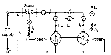
- I1 and I2 are armature currents of motor and generator respectively and Vt is the terminal voltage of both machines.
∴ Input to motor armature = VtI1
If ηm is the motor efficiency, then the output power = ηmVtI1
and if ηg is the generator efficiency,
then input of generator VtI2/ηg
VtI2 = generator output.
Since the generator is driven by motor, from figure Motor output = generator input
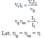
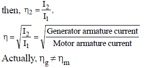
Because,
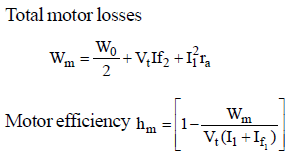
- The motor armature current I1 = I + I2 is greater than generator armature current I2. So armature losses are more in motor than generator.
- The generator field current If2 > motor field current at constant rated speed, iron losses (α speed and flux) is more than motor in generator.
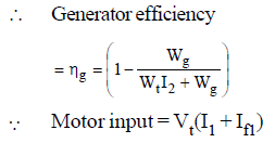
So, efficiency are calculated on consideration of above two reason.
So, no-load rotation loss = Power drawn from the supply-armature losses in both.
 where,
ram = armature resistance of motor and
rag = armature resistance of generator
No-load rotational loss for each machine = Wo/2
when we assume in both case no-load rotational loss are same.

Advantage
- The total power taken from the supply is very low. Therefore this method is very economical.
- Temperature rise and the commutation conditions can be checked under rated condition.
- Stray losses are considered in both machines.
- Efficiency at different loads can be determined.
Disadvantage
- Two identical d.c. machines requirement. Consequently, this test is suitable for manufactures of large d.c. machines.
Field’s test for Series Machines
- In this method, two identical d.c. series machines are required which are then mechanically and electrically coupled together. This test gives efficiencies of both the machines.
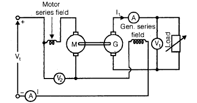
- The iron losses are same in both machines because the series fields of both M and G are connected in series with the motor armature. In order that load is not thrown off accidently, the generator armature is connected to load directly without any switch.
- This method is not regenerative method, because the generator output is wasted in load resistance and not fed to the motor
Let,
Vt = supply voltage
I = motor input current
V1 = generator terminal voltages
I1 = generator output current
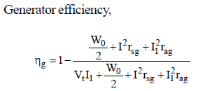
Power input to whole set = VtI
Power output of the generator = V1I1
Total losses in the whole set, W = VtI – V1I1
Total ohmic losses,

where,
ram = motor armature resistance
rag = generator armature resistance
rsg = generator series field resistance etc.
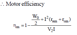
No-load rotational loss of both the machines.
∴ No-load rotational loss of each machine Wo/2
Motor power input = V2I

- At the same time, there is no-difficulty in obtaining two similar d.c. series machines, because these motors used for traction purposes are usually available in pairs.(on the basis of characteristics).
|
23 videos|89 docs|42 tests
|
FAQs on DC Machines- 2 - Electrical Engineering SSC JE (Technical) - Electrical Engineering (EE)
| 1. What is a DC machine? |  |
| 2. How does a DC machine work? |  |
| 3. What are the applications of DC machines? |  |
| 4. What are the differences between a DC motor and a DC generator? |  |
| 5. What are the advantages of DC machines over AC machines? |  |


