Compaction of Soil | Civil Engineering SSC JE (Technical) - Civil Engineering (CE) PDF Download

Introduction
Compaction is the application of mechanical energy to soil so as to rearrange its particles and reduce the void ratio.
It is applied to improve the properties of existing soil or in the process of placing fill such as in the construction of embankments, road bases, runways, earth dams, and reinforced earth walls. Compaction is also used to prepare a level surface during construction of buildings. There is usually no change in the water content and in the size of the individual soil particles.
The objectives of compaction are:
- To increase soil shear strength and therefore its bearing capacity.
- To reduce subsequent settlement under working loads.
- To reduce soil permeability making it more difficult for water to flow through.
Laboratory Compaction
The variation in compaction with water content and compactive effort is first determined in the laboratory. There are several tests with standard procedures such as:
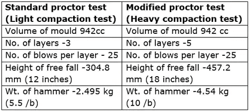
- Indian Standard Light Compaction Test (similar to Standard Proctor Test/Light Compaction Test)
- Indian Standard Heavy Compaction Test (similar to Modified Proctor Test/Heavy Compaction Test)
- Indian Standard Light Compaction Test
Soil is compacted into a 1000 cm3 mould in 3 equal layers, each layer receiving 25 blows of a 2.6 kg rammer dropped from a height of 310 mm above the soil. The compaction is repeated at various moisture contents. - Indian Standard Heavy Compaction Test
It was found that the Light Compaction Test (Standard Test) could not reproduce the densities measured in the field under heavier loading conditions, and this led to the development of the Heavy Compaction Test (Modified Test). The equipment and procedure are essentially the same as that used for the Standard Test except that the soil is compacted in 5 layers, each layer also receiving 25 blows. The same mould is also used. To provide the increased compactive effort, a heavier rammer of 4.9 kg and a greater drop height of 450 mm are used.
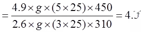
Compactive energy applied per unit
Volume = wHnN/V 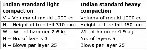
- The ratio of total energy given in heavy compaction test to that given in light compaction test
Dry Density - Water Content Relationship
- To assess the degree of compaction, it is necessary to use the dry unit weight, which is an indicator of compactness of solid soil particles in a given volume.
- Laboratory testing is meant to establish the maximum dry density that can be attained for a given soil with a standard amount of compactive effort.
- In the test, the dry density cannot be determined directly, and as such the bulk density and the moisture content are obtained first to calculate the dry density as

where γd = bulk density, and w = water content.
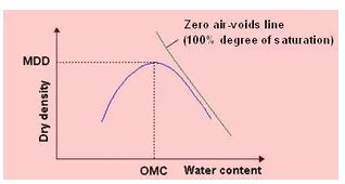
- A series of samples of the soil are compacted at different water contents, and a curve is drawn with axes of dry density and water content. The resulting plot usually has a distinct peak as shown. Such inverted “V” curves are obtained for cohesive soils (or soils with fines), and are known as compaction curves.
- Dry density can be related to water content and degree of saturation (S) as
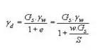
Thus, it can be visualized that an increase of dry density means a decrease of voids ratio and a more compact soil.
Similarly, dry density can be related to percentage air voids (na) as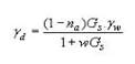
- Relation between moisture content and dry unit weight for a saturated soil is the zero air-voids line. It is not feasible to expel air completely by compaction, no matter how much compactive effort is used and in whatever manner.
Effect of Increasing Water Content
- As water is added to a soil at low moisture contents, it becomes easier for the particles to move past one another during the application of compacting force. The particles come closer, the voids are reduced and this causes the dry density to increase. As the water content increases, the soil particles develop larger water films around them.
- This increase in dry density continues till a stage is reached where the water starts occupying the space that could have been occupied by the soil grains. Thus the water at this stage hinders the closer packing of grains and reduces the dry unit weight. The maximum dry density (MDD) occurs at an optimum water content (OMC), and their values can be obtained from the plot.
Effect of Increasing Compactive Effort
- The effect of increasing compactive effort is shown. Different curves are obtained for different compactive efforts. A greater compactive effort reduces the optimum moisture content and increases the maximum dry density.
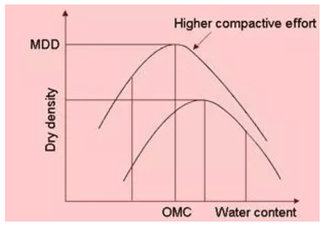
- An increase in compactive effort produces a very large increase in dry density for soil when it is compacted at water contents drier than the optimum moisture content.It should be noted that for moisture contents greater than the optimum, the use of heavier compaction effort will have only a small effect on increasing dry unit weights.
- It can be seen that the compaction curve is not a unique soil characteristic. It depends on the compaction effort. For this reason, it is important to specify the compaction procedure (light or heavy) when giving values of MDD and OMC.
Effect of Method of Compaction
The soil's final dry density is influenced by various aspects of the compaction technique, including: compaction energy, compaction moisture content, compaction method, number of passes, compactor type and size, soil type and gradation, environmental conditions, and compaction control and monitoring.
Effect of Type of Soil
The maximum density attained depends on the type of soil. Coarse-grained soil achieves higher density with lower water content, whereas fine-grained soil achieves lower density, but requires higher water content.
Factors Affecting Compaction
The factors that influence the achieved degree of compaction in the laboratory are:
- Plasticity of the soil
- Water content
- Compactive effort
Compaction of Cohesionless Soils
For cohesionless soils (or soils without any fines), the standard compaction tests are difficult to perform. For compaction, application of vibrations is the most effective method. Watering is another method. To achieve maximum dry density, they can be compacted either in a dry state or in a saturated state.
- For these soil types, it is usual to specify a magnitude of relative density (ID) that must be achieved. If e is the current void ratio or gd is the current dry density, the relative density is usually defined in percentage as
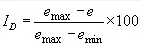
or
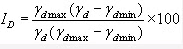
where emax and emin are the maximum and minimum void ratios that can be determined from standard tests in the laboratory, and gdmin and gdmax are the respective minimum and maximum dry densities
On the basis of relative density, sands and gravels can be grouped into different categories: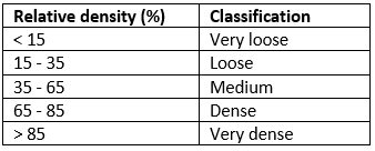
It is not possible to determine the dry density from the value of the relative density. The reason is that the values of the maximum and minimum dry densities (or void ratios) depend on the gradation and angularity of the soil grains.
Engineering Behaviour of Compacted Soils
The water content of a compacted soil is expressed with reference to the OMC. Thus, soils are said to be compacted dry of optimum or wet of optimum (i.e. on the dry side or wet side of OMC). The structure of a compacted soil is not similar on both sides even when the dry density is the same, and this difference has a strong influence on the engineering characteristics.
- Soil Structure
For a given compactive effort, soils have a flocculated structure on the dry side (i.e. soil particles are oriented randomly), whereas they have a dispersed structure on the wet side (i.e. particles are more oriented in a parallel arrangement perpendicular to the direction of applied stress). This is due to the well-developed adsorbed water layer (water film) surrounding each particle on the wet side.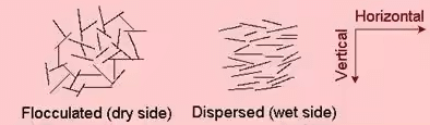
- Swelling
Due to a higher water deficiency and partially developed water films in the dry side, when given access to water, the soil will soak in much more water and then swell more. - Shrinkage
During drying, soils compacted in the wet side tend to show more shrinkage than those compacted in the dry side. In the wet side, the more orderly orientation of particles allows them to pack more efficiently. - Construction Pore Water Pressure
The compaction of man-made deposits proceeds layer by layer, and pore water pressures are induced in the previous layers. Soils compacted wet of optimum will have higher pore water pressures compared to soils compacted dry of optimum, which have initially negative pore water pressure. - Permeability
The randomly oriented soil in the dry side exhibits the same permeability in all directions, whereas the dispersed soil in the wet side is more permeable along particle orientation than across particle orientation. - Compressibility
At low applied stresses, the dry compacted soil is less compressible on account of its truss-like arrangement of particles whereas the wet compacted soil is more compressible.
The stress-strain curve of the dry compacted soil rises to a peak and drops down when the flocculated structure collapses. At high applied stresses, the initially flocculated and the initially dispersed soil samples will have similar structures, and they exhibit similar compressibility and strength.
Some extra details about compaction
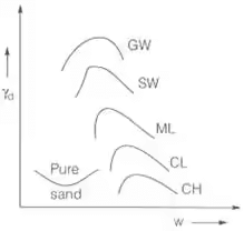
- Coarse grained well graded – Higher γd
- In clays with higher plasticity - γd decrease
- V shape due to bulking of pure sand
|
2 videos|133 docs|55 tests
|
FAQs on Compaction of Soil - Civil Engineering SSC JE (Technical) - Civil Engineering (CE)
| 1. What is soil compaction in civil engineering? |  |
| 2. Why is soil compaction important in construction projects? | |
| 3. How is soil compaction achieved in civil engineering? | |
| 4. What are the factors that affect soil compaction? | |
| 5. What are the common methods used for measuring soil compaction? | |


MCQs
,Summary
,shortcuts and tricks
,Previous Year Questions with Solutions
,ppt
,Viva Questions
,Semester Notes
,past year papers
,Extra Questions
,practice quizzes
,Compaction of Soil | Civil Engineering SSC JE (Technical) - Civil Engineering (CE)
,Free
,Compaction of Soil | Civil Engineering SSC JE (Technical) - Civil Engineering (CE)
,video lectures
,mock tests for examination
,Sample Paper
,Important questions
,Compaction of Soil | Civil Engineering SSC JE (Technical) - Civil Engineering (CE)
,Objective type Questions
,Exam
,study material
;


Compaction of Soil Free PDF Download
Importance of Compaction of Soil
Compaction of Soil Notes
Compaction of Soil Civil Engineering (CE) Questions
Study Compaction of Soil on the App
|
© EduRev
|
Education Revolution
|


|


within 7 days!