Basic Concepts of Speed Control of DC & AC Motors | Electrical Engineering Optional Notes for UPSC PDF Download

Chapter 10
Basic Concepts of speed Control of DC and AC Motors
Speed control of DC Motors Terminal voltage of a DC motor is given by : V = Eb + Ia Ra
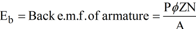
Where,
P = Number of poles
ø = Maximum flux per pole (Wb)
Z = Total number of armature conductors
N = Speed of the armature in r.p.s.
A = Number of parallel paths
Ia = Armature current
Ra= Armature resistance
Also,ø α If (Field current)
ø = KIf
Where K = constant
Speed 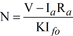
Neglecting IaRa drop N = 
Speed is directly proportional to supply voltage V. Hence, thyristors are used in various combinations tor speed control by adjustment of supply voltage to armature or the field winding as the angle of conduction is controlled.
Three basic methods are used to obtain variable AC. voltage from a fixed supply voltage (AC. or DC) by
(a) Phase control: When supply is AC the current is controlled to flow from the supply to the motor for a fraction of each positive half cycle; this is repeated cyclically. This type of control can be applied for all motor ratings,
(b) Integral cycle control: From AC supply the current is made to flow for a number of complete cycles and quenched for a further number of cycles and the sequence of operation is repeated. ‘On’ ‘Off duration ratio is adjusted by control. This method is useful for small motors fractional kW size,
(c) Chopper control: A DC voltage can be switched on and off rapidly and repeatedly by means of a thyristor to a DC motor. The average DC voltage is controlled by varying on/off time ratio. This type ot control is used for traction motors.
Phase Control All the uncontrolled rectifiers give an output DC voltage which has a constant average value. If some of all or the diodes are replaced by thyristors, output voltage is adjusted by phase control. Thyristor controlled converter basic circuits with wavefor.m.s. are explained below.
1. Single phase half wave converter: Here power is only half the available and hence the method is used for fractional horse power motors.
The angle of conduction is controlled by the gate pulse. A free wheeling diode D2 is connected across the motor to conduct during the negative half-cycle to nullify the armature active inductive current stored during positive half cycle.
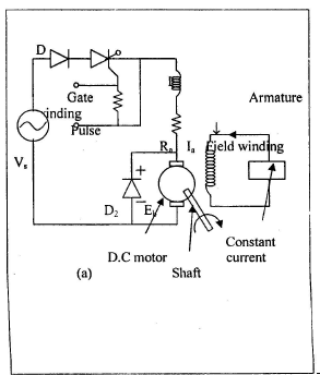
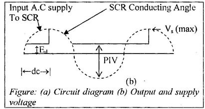
The average DC voltage is
Edc = Em/2π ( 1 + cosα)
2. Single Phase full wave converter : This method is used for motor from 1 kW to 20 kW ans inversion does not take place
|
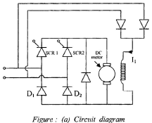
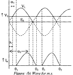
The armature current flows when the applied voltage from SCRs is more than the bakc e.m.f. Eb, i.e.. between α1 and α2 from figure. If one half of bridge is fired at α1, the armature current flow starts from θ1, reaches a peak wen two voltage are equal at θ2 to θ2 is due to stored energy in armature inductance. The same condition repeats when second section of bridge conducts. The armature current can be continuous and discontinuous.
Discontinuous current is given by
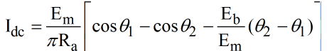
Continuous current is
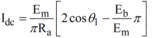
Fully controlled bridge can also be used for speed control AC motors. The voltage and current wavefor. m.s. are same as half controlled bridge.
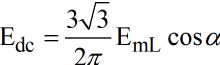
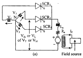
3. Three phase half wave converter : Three phase controlled converters are used for control of motors from a few kW to hundreds of kW. A 3-phase half-wave control circuit is shown in figure Thyrisotor firing angle is between [π/6] and [5π/ 6].
The average output voltage is
 |
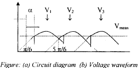 |
4. Three phase half- controlled bridge converter Circuit diagram and output voltage waveform are shown in figure .
 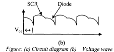 |
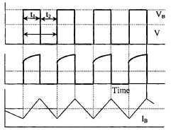
Intergal Cycle Control The supply is switched on for an integral number of cycles C1 and is made off for further number of integral C2. Thus one on/off cycle is for time C= C1 + C2. This on/off cycle is repreated cyclically. The switching is effected by mean of thyristor as shown in figure. Free wheeling is provided by rectifier bridge diodes.
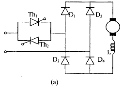 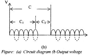 |
The speed control is ibtained by varying C1/C2. smooth operation is achieved when c is between 10 and 20 and C1/C2 is less than unity. Intergral cycle control, triggering of thyristor occurs at zero voltage.
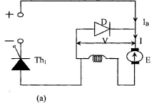
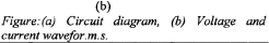
CHOPPER CONTROL
A thyristor chopper can be used to obtain variable output voltage from a constant DC supply source, e.g. battery or DC railway traction supply. The voltage control is obtained by chopping and this is an economical method of controlling speed and torque of a DC motor with battery supply or traction motors.
The circuit voltage and current wave for.m.s. are shown in figure.
   |
|
550 videos|588 docs|343 tests
|
FAQs on Basic Concepts of Speed Control of DC & AC Motors - Electrical Engineering Optional Notes for UPSC
| 1. What is the purpose of speed control in DC and AC motors? |  |
| 2. How is speed control achieved in DC motors? | |
| 3. What are the different methods of speed control in AC motors? | |
| 4. Can speed control affect the torque output of the motor? | |
| 5. What are the advantages of speed control in motors? | |


past year papers
,Basic Concepts of Speed Control of DC & AC Motors | Electrical Engineering Optional Notes for UPSC
,MCQs
,Viva Questions
,Summary
,Exam
,Semester Notes
,Objective type Questions
,video lectures
,practice quizzes
,Extra Questions
,mock tests for examination
,Basic Concepts of Speed Control of DC & AC Motors | Electrical Engineering Optional Notes for UPSC
,Sample Paper
,ppt
,Free
,study material
,Previous Year Questions with Solutions
,shortcuts and tricks
,Important questions
,Basic Concepts of Speed Control of DC & AC Motors | Electrical Engineering Optional Notes for UPSC
;


Basic Concepts of Speed Control of DC & AC Motors Free PDF Download
Importance of Basic Concepts of Speed Control of DC & AC Motors
Basic Concepts of Speed Control of DC & AC Motors Notes
Basic Concepts of Speed Control of DC & AC Motors UPSC Questions
Study Basic Concepts of Speed Control of DC & AC Motors on the App
|
© EduRev
|
Education Revolution
|


|


within 7 days!