Network Theorems

Network theorems are fundamental principles used in electrical engineering to analyze and simplify complex electrical circuits. These theorems help in determining the voltage, current, and power across various elements of the circuit. Here are some of the key network theorems:
1. Thevenin's Theorem
- Any two-terminal linear bilateral network can be replaced by a voltage source in series with an impedance.
- The voltage source is the voltage across the open-circuited terminals and series impedance is the equivalent impedance seen across the terminals by replacing all the sources in-network with their internal impedances.
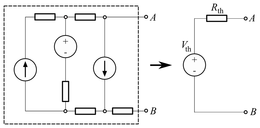
Vth → Thevenin's voltage = Voc across AB.
Rth → Thevenin's equivalent impedance.
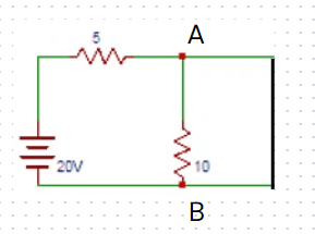
Example: Consider the circuit shown below. Find the equivalent Thevenin's voltage between nodes A and B.
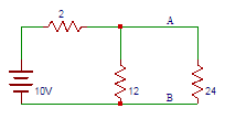 Solution: Thevenin's voltage is equal to the open-circuit voltage across the terminals AB that is across 12Ω resistors.
Now by voltage divider rule,
VTH = 10×12/(12+2) = 10×12/14 = 8.57V.
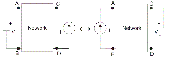
2. Norton's Theorem
- Any two-terminal linear bilateral network containing active and passive elements can be replaced by an equivalent current source in parallel to an equivalent impedance current source is equal to the short-circuited current through the given terminals and equivalent impedance is the impedance seen across the terminals by replacing all the sources with their internal impedance.
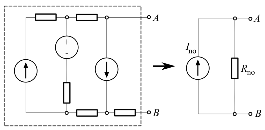
Ino → Norton's equivalent current
Rno → Norton's equivalent impedance.
Rno= Zth
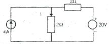
Example: Find the current flowing between terminals A and B of the circuit shown below.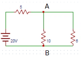 Solution: The magnitude of the current in Norton's equivalent circuit is equal to the current passing through the short-circuited terminals that are
Let us first calculate RTH,
RN=RTH=(5x10)/(5+10) = 10/3 ohm
Voltage drop across AB = VAB =(20x10)/(10+5) = 40/3 V
IN=(40/3)/(10/3)=4A.
3. Superposition Theorem
- This theorem states that if a no. of voltage sources or current sources are acting together in a bilateral network then the resultant current voltage in any branch is an algebraic sum of current/voltage due to individual sources by replacing them with their internal impedance.
- The superposition theorem is applicable to linear time varying and LTI(Linear Time Invariant) networks.
- It is also applicable for circuits having the initial conditions. It is applicable for the linear networks.
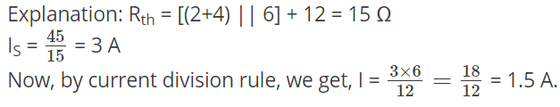
Example: For the given circuit, the current I is:
(a) 2 A
(b) 5A
(c) 7 A
(d) 9A
Solution:
(c) 7A
Using superposition theorem:
Due to current source:
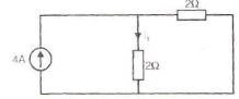
I1 = (2/2+2).4 = 2A
Due to voltage source: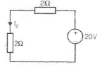

Current I = I1 + I2
⇒ I = 2 + 5
⇒ I = 7A
Try yourself: In Superposition theorem, while considering a source, all other current sources are?
4. Reciprocity Theorem
- This theorem states that in a linear bilateral reciprocal network if I is the current in branch X due to a voltage source V in-branch Y then same current will flow in branch Y when the same voltage source is connected in branch X.
- The initial conditions are assumed to be zero in reciprocity theorem.
- There should not be any extra dependent or independent sources in network.
Example: In the circuit given below, the current in the 4-ohm resistor is __________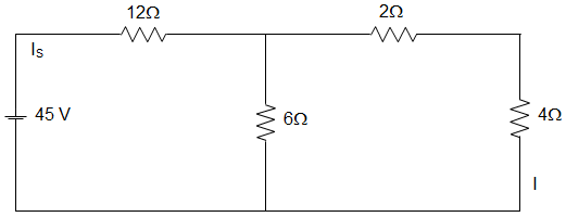
Try yourself: In the circuit given below, the current through the 6 Ω resistance is _________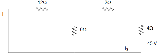
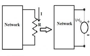
5. Maximum Power Transfer Theorem
- The following maximum power transfer theorems determine the values of the load impedance which results in maximum power transfer across the terminals of an active network.
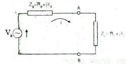
- We consider a series combination of source and fixed complex impedance delivering power to a load consisting of a variable resistance or a variable complex impedance.
Case 1: Load is variable resistance RL
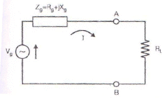
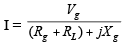
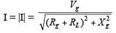
Power delivered to RL is:
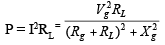
To determine the value of R for maximum power transferred to the load,

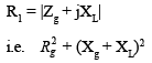
We arrive at the condition:
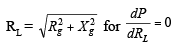
Hence, with a variable pure resistance load the maximum power is delivered across the terminals of the active network if the load resistance is made equal to the absolute value of the active network impedance.
If the reactive component of the impedance in series with source is zero i.e., Xg = 0, then the maximum power is transferred to the load when the load and source resistances are equal i.e., RL = Rg.
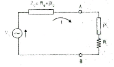
Case 2: Load Impedance ZL with variable resistance and variable reactance.
For maximum power transfer: RL= Rg, XL = -Xg i.e. ZL = Zg
With the load impedance consisting of variable resistance and variable reactance, maximum power transfer across the terminals of the active network occurs when the load impedance Z1 is equal to the complex conjugate of the network impedance Zg.
Case 3: Load impedance, ZL with variable resistance, and fixed reactance.
For maximum power transfer.
6. Compensation Theorem
- The compensation theorem is useful in determining the current and voltage changes in a circuit element when the value of its impedance is changed.
- This application occurs in bridge and potentiometer circuits where a slight change in one impedance results in shift from the null condition.
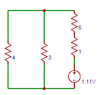
- In a linear time-invariant bilateral network if the resistance R of a branch is changed by ΔR then the currents in all branches of the network will change and this change in current can be found by connecting a voltage source VC such that VC = i ΔR in series with resistance (R +ΔR ).
- Here the current i represent current through R before change and all sources are replaced by their internal impedance to find out the change in current.
Example: Find the current through 3Ω resistors in the circuit shown below.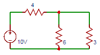 Solution: Total resistance in the circuit = 2+[3||(2+2||2)] = 3.5Ω. The total current drawn by the circuit =10/(4+6||3) = 1.67A. Current through 3Ω resistor = 1.11A ≅1A.
Try yourself: Determine the current flowing in the ammeter having 1Ω internal resistance connected in series with the 6Ω resistor as shown in the below circuit.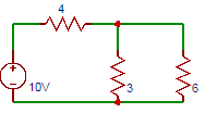
7. Tellegen's Theorem
- This theorem states that the algebraic sum of power consumed and delivered by each branch of a network is always zero.

n= no. of branches of the network, vK =voltage across Kth branch.
Try yourself: Consider the circuit shown below. Find whether the circuit satisfies Tellegan’s theorem.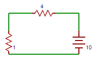

8. Millman's Theorem
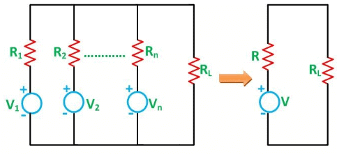
- Millman's Theorem states that - when a number of voltage sources (V1, V2, V3......... Vn) are in parallel having internal resistance (R1, R2, R3.............Rn) respectively, the arrangement can replace by a single equivalent voltage source V in series with an equivalent series resistance R.
- In other words; it determines the voltage across the parallel branches of the circuit, which have more than one voltage source, i.e., reduces the complexity of the electrical circuit.
- This Theorem is given by Jacob Millman. The utility of Millman's Theorem is that the number of parallel voltage sources can be reduced to one equivalent source. It is applicable only to solve the parallel branch with one resistance connected to one voltage source or current source. It is also used in solving networks having an unbalanced bridge circuit.
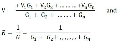
- As per Millman's Theorem:
Try yourself: The resistance of a strip of copper of rectangular cross section is 2 Ω. A metal of resistivity twice that of a copper is coated on its upper surface to a thickness equal to that of copper strip. The resistance of composite strip will be _________
9. Substitution Theorem
- A known voltage in a branch can be replaced by an ideal voltage source.
- This theorem applies to any network, linear or non-linear, time varying or time-invariant.
- It is applicable both in the time domain and in the 's' domain.
Explanation of Substitution Theorem
- Let us take a circuit as shown in fig - a,
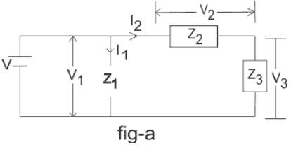
- Let, V is supplied voltage and Z1, Z2 and Z3 is different circuit impedances. V1, V2 and V3 are the voltages across Z1, Z2 and Z3 impedance respectively and I is the supplied current whose I1 part is flowing through the Z1 impedance whereas I2 part is flowing through the Z2 and Z3 impedance.
- Now if we replace Z3 impedance with V3 voltage source as shown in fig-b or with I2 current source as shown in fig-c then according to Substitution Theorem all initial conditions through other impedances and source will remain unchanged.
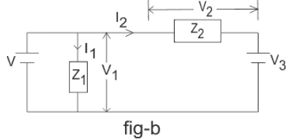
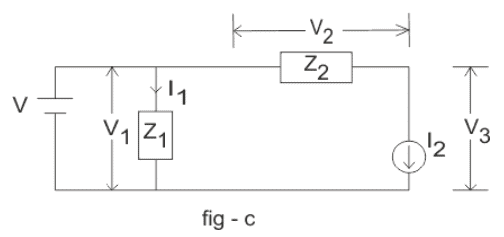
- i.e. - current through source will be I, voltage across Z1 impedance will be V1, the current through Z2 will be I2 etc.
FAQs on Network Theorems
| 1. What's the difference between Thevenin's theorem and Norton's theorem in circuit analysis? |  |
| 2. How do I apply superposition theorem when a circuit has multiple independent sources? | |
| 3. Why does maximum power transfer occur at a specific load resistance value? | |
| 4. What's the practical difference between applying mesh analysis and nodal analysis for solving circuits? | |
| 5. Can I use reciprocity theorem to predict circuit behaviour without calculating every parameter? | |


 | Explore Courses for Electrical Engineering (EE) exam |
 | Get EduRev Notes directly in your Google search |