Electrical Engineering (EE) Exam > Electrical Engineering (EE) Notes > Network Theory (Electric Circuits) > Kirchhoff's Circuit Laws: KCL & KVL
Kirchhoff's Circuit Laws: KCL & KVL | Network Theory (Electric Circuits) - Electrical Engineering (EE) PDF Download
| Table of contents |
|
| Introduction |
|
| Kirchhoffs First Law – The Current Law, (KCL) |
|
| Kirchhoffs Second Law – The Voltage Law, (KVL) |
|
| Common DC Circuit Theory Terms: |
|

Introduction
-
- Using Kirchhoffs circuit law relating to the junction rule and his closed loop rule, we can calculate and find the currents and voltages around any closed circuit providing we know the values of the electrical components within it.
- We saw in the Resistors tutorial that a single equivalent resistance, (RT) can be found when two or more resistors are connected together in either series, parallel or combinations of both, and that these circuits obey Ohm’s Law.
- However, sometimes in complex circuits such as bridge or T networks, we can not simply use Ohm’s Law alone to find the voltages or currents circulating within the circuit. For these types of calculations we need certain rules which allow us to obtain the circuit equations and for this we can use Kirchhoffs Circuit Law.
- In 1845, a German physicist, Gustav Kirchhoff developed a pair or set of rules or laws which deal with the conservation of current and energy within electrical circuits. These two rules are commonly known as: Kirchhoffs Circuit Laws with one of Kirchhoffs laws dealing with the current flowing around a closed circuit, Kirchhoffs Current Law, (KCL) while the other law deals with the voltage sources present in a closed circuit, Kirchhoffs Voltage Law, (KVL).
Kirchhoffs First Law – The Current Law, (KCL)
- Kirchhoffs Current Law or KCL, states that the “total current or charge entering a junction or node is exactly equal to the charge leaving the node as it has no other place to go except to leave, as no charge is lost within the node“. In other words the algebraic sum of ALL the currents entering and leaving a node must be equal to zero, I(exiting) + I(entering) = 0. This idea by Kirchhoff is commonly known as the Conservation of Charge.
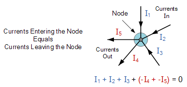
- Here, the three currents entering the node, I1, I2, I3 are all positive in value and the two currents leaving the node, I4 and I5 are negative in value. Then this means we can also rewrite the equation as;
I1 + I2 + I3 – I4 – I5 = 0 - The term Node in an electrical circuit generally refers to a connection or junction of two or more current carrying paths or elements such as cables and components. Also for current to flow either in or out of a node a closed circuit path must exist. We can use Kirchhoff’s current law when analysing parallel circuits.
Kirchhoffs Second Law – The Voltage Law, (KVL)
- Kirchhoffs Voltage Law or KVL, states that “in any closed loop network, the total voltage around the loop is equal to the sum of all the voltage drops within the same loop” which is also equal to zero. In other words the algebraic sum of all voltages within the loop must be equal to zero. This idea by Kirchhoff is known as the Conservation of Energy.
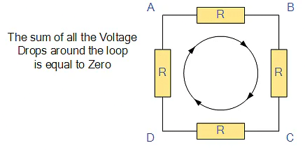
- Starting at any point in the loop continue in the same direction noting the direction of all the voltage drops, either positive or negative, and returning back to the same starting point. It is important to maintain the same direction either clockwise or anti-clockwise or the final voltage sum will not be equal to zero. We can use Kirchhoff’s voltage law when analysing series circuits.
- When analysing either DC circuits or AC circuits using Kirchhoffs Circuit Laws a number of definitions and terminologies are used to describe the parts of the circuit being analysed such as: node, paths, branches, loops and meshes. These terms are used frequently in circuit analysis so it is important to understand them.
Common DC Circuit Theory Terms:
- Circuit – a circuit is a closed loop conducting path in which an electrical current flows.
- Path – a single line of connecting elements or sources.
- Node – a node is a junction, connection or terminal within a circuit were two or more circuit elements are connected or joined together giving a connection point between two or more branches. A node is indicated by a dot.
- Branch – a branch is a single or group of components such as resistors or a source which are connected between two nodes.
- Loop – a loop is a simple closed path in a circuit in which no circuit element or node is encountered more than once.
- Mesh – a mesh is a single closed loop series path that does not contain any other paths. There are no loops inside a mesh.
Note that:
- Components are said to be connected together in Series if the same current value flows through all the components.
- Components are said to be connected together in Parallel if they have the same voltage applied across them.
A Typical DC Circuit
Kirchhoffs Circuit Law Example
Find the current flowing in the 40Ω Resistor, R3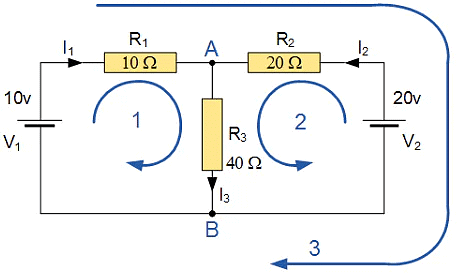
Application of Kirchhoffs Circuit Laws
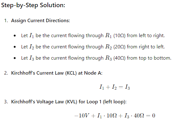
- These two laws enable the Currents and Voltages in a circuit to be found, ie, the circuit is said to be “Analysed”, and the basic procedure for using Kirchhoff’s Circuit Laws is as follows:
- Assume all voltages and resistances are given. ( If not label them V1, V2,… R1, R2, etc. )
- Assigns a current to each branch or mesh (clockwise or
- anticlockwise)
- Label each branch with a branch current. ( I1, I2, I3 etc. )
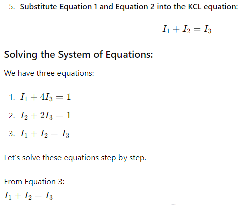
- Find Kirchhoff’s first law equations for each node.
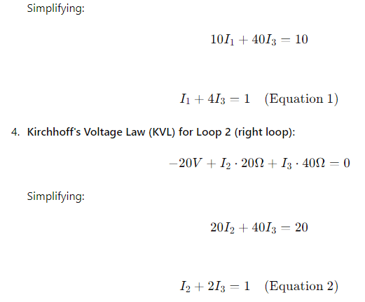
- Find Kirchhoff’s second law equations for each of the independent loops of the circuit.
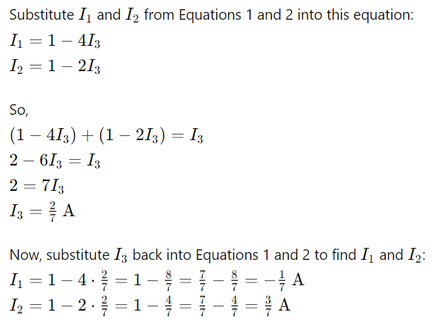
- Use Linear simultaneous equations as required to find the unknown currents.
As well as using Kirchhoffs Circuit Law to calculate the various voltages and currents circulating around a linear circuit, we can also use loop analysis to calculate the currents in each independent loop which helps to reduce the amount of mathematics required by using just Kirchhoff’s laws.
The document Kirchhoff's Circuit Laws: KCL & KVL | Network Theory (Electric Circuits) - Electrical Engineering (EE) is a part of the Electrical Engineering (EE) Course Network Theory (Electric Circuits).
All you need of Electrical Engineering (EE) at this link: Electrical Engineering (EE)
|
73 videos|139 docs|62 tests
|
FAQs on Kirchhoff's Circuit Laws: KCL & KVL - Network Theory (Electric Circuits) - Electrical Engineering (EE)
| 1. What is Kirchhoff's First Law and how is it applied in circuit analysis? |  |
Ans. Kirchhoff's First Law, also known as the Current Law (KCL), states that the total current entering a junction in a circuit is equal to the total current leaving the junction. This law is applied by setting up equations at junctions in a circuit to ensure that current is conserved.
| 2. How is Kirchhoff's Second Law, the Voltage Law (KVL), used in circuit analysis? | |
Ans. Kirchhoff's Second Law, or the Voltage Law (KVL), states that the sum of the voltage drops in a closed loop in a circuit is equal to the applied voltage. This law is applied by setting up equations around loops in a circuit to analyze the voltage distribution.
| 3. What are some common DC circuit theory terms related to Kirchhoff's laws? | |
Ans. Some common DC circuit theory terms related to Kirchhoff's laws include nodes, branches, loops, resistors, capacitors, and inductors. Understanding these terms is crucial for applying Kirchhoff's laws in circuit analysis.
| 4. How do Kirchhoff's Circuit Laws help in solving complex circuit problems? | |
Ans. Kirchhoff's Circuit Laws, KCL and KVL, provide a systematic approach to solving complex circuit problems by applying conservation principles. By setting up equations based on these laws, it becomes possible to analyze and solve circuits with multiple components and sources.
| 5. What are some practical applications of Kirchhoff's laws in real-world circuit design and analysis? | |
Ans. Kirchhoff's laws are widely used in real-world circuit design and analysis, such as in electronics, electrical engineering, and telecommunications. They are essential tools for analyzing and troubleshooting circuits in various applications, ranging from simple circuits to complex systems.
About this Document

4.94/5
Rating

Sep 29, 2025
Last updated
Related Exams
Document Description: Kirchhoff's Circuit Laws: KCL & KVL for Electrical Engineering (EE) 2025 is part of Network Theory (Electric Circuits) preparation.
The notes and questions for Kirchhoff's Circuit Laws: KCL & KVL have been prepared according to the Electrical Engineering (EE) exam syllabus. Information about Kirchhoff's Circuit Laws: KCL & KVL covers topics
like Introduction, Kirchhoffs First Law – The Current Law, (KCL), Kirchhoffs Second Law – The Voltage Law, (KVL), Common DC Circuit Theory Terms: and Kirchhoff's Circuit Laws: KCL & KVL Example, for Electrical Engineering (EE) 2025 Exam. Find important definitions, questions, notes, meanings, examples, exercises and tests below for Kirchhoff's Circuit Laws: KCL & KVL.
Introduction of Kirchhoff's Circuit Laws: KCL & KVL in English is available as part of our Network Theory (Electric Circuits)
for Electrical Engineering (EE) & Kirchhoff's Circuit Laws: KCL & KVL in Hindi for Network Theory (Electric Circuits) course.
Download more important topics related with notes, lectures and mock test series for Electrical Engineering (EE)
Exam by signing up for free. Electrical Engineering (EE): Kirchhoff's Circuit Laws: KCL & KVL | Network Theory (Electric Circuits) - Electrical Engineering (EE)
Description
Full syllabus notes, lecture & questions for Kirchhoff's Circuit Laws: KCL & KVL | Network Theory (Electric Circuits) - Electrical Engineering (EE) - Electrical Engineering (EE) | Plus excerises question with solution to help you revise complete syllabus for Network Theory (Electric Circuits) | Best notes, free PDF download
Information about Kirchhoff's Circuit Laws: KCL & KVL
In this doc you can find the meaning of Kirchhoff's Circuit Laws: KCL & KVL defined & explained in the simplest way possible. Besides explaining types of
Kirchhoff's Circuit Laws: KCL & KVL theory, EduRev gives you an ample number of questions to practice Kirchhoff's Circuit Laws: KCL & KVL tests, examples and also practice Electrical Engineering (EE)
tests

Related Searches
Summary
,practice quizzes
,ppt
,shortcuts and tricks
,Viva Questions
,Kirchhoff's Circuit Laws: KCL & KVL | Network Theory (Electric Circuits) - Electrical Engineering (EE)
,Semester Notes
,past year papers
,Objective type Questions
,MCQs
,Important questions
,Kirchhoff's Circuit Laws: KCL & KVL | Network Theory (Electric Circuits) - Electrical Engineering (EE)
,video lectures
,Free
,Previous Year Questions with Solutions
,Kirchhoff's Circuit Laws: KCL & KVL | Network Theory (Electric Circuits) - Electrical Engineering (EE)
,mock tests for examination
,study material
,Sample Paper
,Exam
,Extra Questions
;


Additional Information about Kirchhoff's Circuit Laws: KCL & KVL for Electrical Engineering (EE) Preparation
Kirchhoff's Circuit Laws: KCL & KVL Free PDF Download
The Kirchhoff's Circuit Laws: KCL & KVL is an invaluable resource that delves deep into the core of the Electrical Engineering (EE) exam.
These study notes are curated by experts and cover all the essential topics and concepts, making your preparation more efficient and effective.
With the help of these notes, you can grasp complex subjects quickly, revise important points easily,
and reinforce your understanding of key concepts. The study notes are presented in a concise and easy-to-understand manner,
allowing you to optimize your learning process. Whether you're looking for best-recommended books, sample papers, study material,
or toppers' notes, this PDF has got you covered. Download the Kirchhoff's Circuit Laws: KCL & KVL now and kickstart your journey towards success in the Electrical Engineering (EE) exam.
Importance of Kirchhoff's Circuit Laws: KCL & KVL
The importance of Kirchhoff's Circuit Laws: KCL & KVL cannot be overstated, especially for Electrical Engineering (EE) aspirants.
This document holds the key to success in the Electrical Engineering (EE) exam.
It offers a detailed understanding of the concept, providing invaluable insights into the topic.
By knowing the concepts well in advance, students can plan their preparation effectively.
Utilize this indispensable guide for a well-rounded preparation and achieve your desired results.
Kirchhoff's Circuit Laws: KCL & KVL Notes
Kirchhoff's Circuit Laws: KCL & KVL Notes offer in-depth insights into the specific topic to help you master it with ease.
This comprehensive document covers all aspects related to Kirchhoff's Circuit Laws: KCL & KVL.
It includes detailed information about the exam syllabus, recommended books, and study materials for a well-rounded preparation.
Practice papers and question papers enable you to assess your progress effectively.
Additionally, the paper analysis provides valuable tips for tackling the exam strategically.
Access to Toppers' notes gives you an edge in understanding complex concepts.
Whether you're a beginner or aiming for advanced proficiency, Kirchhoff's Circuit Laws: KCL & KVL Notes on EduRev are your ultimate resource for success.
Kirchhoff's Circuit Laws: KCL & KVL Electrical Engineering (EE) Questions
The "Kirchhoff's Circuit Laws: KCL & KVL Electrical Engineering (EE) Questions" guide is a valuable resource for all aspiring students preparing for the
Electrical Engineering (EE) exam. It focuses on providing a wide range of practice questions to help students gauge
their understanding of the exam topics. These questions cover the entire syllabus, ensuring comprehensive preparation.
The guide includes previous years' question papers for students to familiarize themselves with the exam's format and difficulty level.
Additionally, it offers subject-specific question banks, allowing students to focus on weak areas and improve their performance.
Study Kirchhoff's Circuit Laws: KCL & KVL on the App
Students of Electrical Engineering (EE) can study Kirchhoff's Circuit Laws: KCL & KVL alongwith tests & analysis from the EduRev app,
which will help them while preparing for their exam. Apart from the Kirchhoff's Circuit Laws: KCL & KVL,
students can also utilize the EduRev App for other study materials such as previous year question papers, syllabus, important questions, etc.
The EduRev App will make your learning easier as you can access it from anywhere you want.
The content of Kirchhoff's Circuit Laws: KCL & KVL is prepared as per the latest Electrical Engineering (EE) syllabus.
|
© EduRev
|
Education Revolution
|


|


Signup to see your scores
go up within 7 days!
Access 1000+ FREE Docs, Videos and Tests
Takes less than 10 seconds to signup