Carry Look Ahead Adders: Binary Arithmetic Circuits | Analog and Digital Electronics - Electrical Engineering (EE) PDF Download

Carry Look Ahead Adders
The adders described in this module are generally called Ripple Carry Adders because of the way that the carry bit is propagated from one stage of the adder to the next, rippling through the chain of full adders until the carry out is produced at the carry out pin of the final stage.
This process takes some time, which is proportional to the number of bits added. Although this may be a minor problem in small adders, with an increase in the number of bits in the binary words to be added, the time delay before the final carry out is produced becomes unacceptable.
To overcome this problem, IC manufacturers offer a range of ‘Carry Look Ahead Adders’ in which the addition and carry out are produced simultaneously. The system uses complex combinational logic to assess whether, at each individual adder a carry will be produced, based on the state of the A and B inputs to that stage, and the logic state of the carry in bit to the first stage.
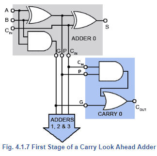
Fig. 4.1.7 shows an arrangement for producing a carry out by splitting the full adder into a partial full adder (grey block), which has two additional outputs, a propagate (P) output that takes a logic 1 output whenever inputs A and B are 1,0 or 0,1 and a generate (G) output that will be logic 1 whenever the A and B inputs are at 1,1. Using this information it is possible to decide on the logic state of the carry out depending on a combination of the CIN state and the A and B states.
In the carry generator (blue block), the P input is ANDed with the CIN and ORed with the G input to produce a carry out. The carry out is fed to the successive adders in the normal way, but the CIN P and G signals are fed in parallel to the other adder stages, where the state of the carry out for each adder stage can be ascertained from the shared CIN signal and the A and B states for the successive stages, depending on the input states at each stage, rather than waiting for the calculations to complete at all the stages.
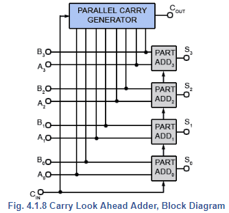
A generalised arrangement in block diagram form (Fig.4.1.8) shows the carry out (COUT) being produced by the parallel carry generator from the A and B input signals and the CIN signal, rather than from the carry out of the final adder stage as in the ripple adders.
The use of look ahead adders is important in practical circuits, not only to speed up operation but because to have an adder that produces part of its answer (the sum) at one time, and another part of its answer (the carry out) at another time, would cause timing problems in other parts of the circuit.
|
135 videos|167 docs|71 tests
|
FAQs on Carry Look Ahead Adders: Binary Arithmetic Circuits - Analog and Digital Electronics - Electrical Engineering (EE)
| 1. What is a carry look ahead adder? |  |
| 2. How does a carry look ahead adder work? | |
| 3. What are the advantages of using carry look ahead adders? | |
| 4. Are there any limitations or drawbacks of carry look ahead adders? | |
| 5. In what applications are carry look ahead adders commonly used? | |


Viva Questions
,Objective type Questions
,shortcuts and tricks
,study material
,Free
,MCQs
,Extra Questions
,Exam
,Carry Look Ahead Adders: Binary Arithmetic Circuits | Analog and Digital Electronics - Electrical Engineering (EE)
,Sample Paper
,Carry Look Ahead Adders: Binary Arithmetic Circuits | Analog and Digital Electronics - Electrical Engineering (EE)
,Previous Year Questions with Solutions
,video lectures
,Summary
,Semester Notes
,ppt
,practice quizzes
,mock tests for examination
,Important questions
,past year papers
,Carry Look Ahead Adders: Binary Arithmetic Circuits | Analog and Digital Electronics - Electrical Engineering (EE)
;


Carry Look Ahead Adders: Binary Arithmetic Circuits Free PDF Download
Importance of Carry Look Ahead Adders: Binary Arithmetic Circuits
Carry Look Ahead Adders: Binary Arithmetic Circuits Notes
Carry Look Ahead Adders: Binary Arithmetic Circuits Electrical Engineering (EE) Questions
Study Carry Look Ahead Adders: Binary Arithmetic Circuits on the App
|
© EduRev
|
Education Revolution
|


|


