
Best Study Material for Electrical Engineering (EE) Exam
Electrical Engineering (EE) Exam > Electrical Engineering (EE) Notes > Analog and Digital Electronics > Multi Bit Multiplexers & Addressing
Multi Bit Multiplexers & Addressing | Analog and Digital Electronics - Electrical Engineering (EE) PDF Download
Multi−Bit Multiplexers
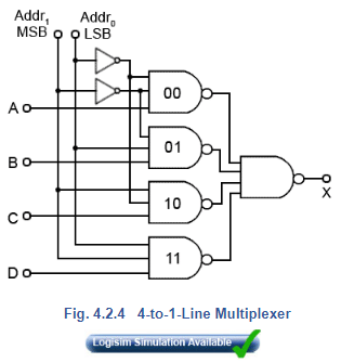
There are many uses for multiplexers. Wherever a number of signals, or logic states, need to be passed down a single communication channel such as a wire, a radio channel, or a telephone, some form of multiplexing is used. Sometimes the multiplexing and de-multiplexing can be very complex, much more so than the circuit in Figs 4.2.2 and 4.2.3. In some systems, data is transferred over very long distances, in others such as transferring data within computers, the distances may be very short. Fig. 4.2.4 shows a 4 to 1 line multiplexer, which enables a 4-bit binary number to be passed over 3 lines, one for data and two for control.
Addressing
Larger multiplexers, such as 4, 8 or 16 bit types, which are readily available in IC form, use a method of ‘addressing’ a particular data gate using a binary code. Fig 4.2.4 shows a 4 to 1 multiplexer where, in order to output data from a particular input, one of the four 3−input NAND gates must be enabled by a logic 1 on two of its inputs, leaving the third input for data. To achieve this two address lines are used, giving four possible combinations of 1 and 0. Look carefully at the address lines. When both are at logic 0 the two inverters (NOT gates) produce logic 1s at two of the inputs to NAND gate 00. None of the other NAND gates addressed by these lines has both its address inputs at logic 1. If the least significant bit (lsb) of the address is 1 and the most significant bit (msb) is 0 then NAND gate 01 is enabled. Because two address lines can give four possible binary combinations, you should find that, counting from the top, gate 00 is enabled by the address inputs 002, gate 01 by address 012, gate 10 by 102 and gate 11 by 112.
Multiplexer IC Datasheets
There are many commercially available multiplexer ICs available with a variety of extra features. The following is a list of datasheets for some basic multiplexers similar to those described in this article.
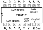
74HC151 8 To 1 multiplexer from NXP
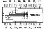
74HC153 4To 1 multiplexer from Texas instruments
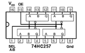
74HC257 Quad 2input Multiplexer from NXP
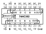
74HC352Dual 4 to 1 Multiplexer from Texas instruments
The document Multi Bit Multiplexers & Addressing | Analog and Digital Electronics - Electrical Engineering (EE) is a part of the Electrical Engineering (EE) Course Analog and Digital Electronics.
All you need of Electrical Engineering (EE) at this link: Electrical Engineering (EE)
|
137 videos|144 docs|71 tests
|


FAQs on Multi Bit Multiplexers & Addressing - Analog and Digital Electronics - Electrical Engineering (EE)
| 1. What is a multi-bit multiplexer? |  |
| 2. How does a multi-bit multiplexer work? | |
Ans. A multi-bit multiplexer works by using a combination of control signals to select the desired input signal. The control signals are typically in binary form, and they determine which input is connected to the output. The number of control signals required depends on the number of input signals the multiplexer can handle.
| 3. What is the purpose of addressing in a multi-bit multiplexer? | |
Ans. Addressing in a multi-bit multiplexer refers to the process of selecting the desired input signal using control signals. The control signals act as addresses for the different input signals, allowing the multiplexer to access and output the correct data.
| 4. Can a multi-bit multiplexer handle different data sizes? | |
Ans. Yes, a multi-bit multiplexer can handle different data sizes. The number of input signals and the size of each input signal can vary based on the design of the multiplexer. It is important to ensure that the control signals are compatible with the data sizes to avoid any errors.
| 5. What are the advantages of using a multi-bit multiplexer? | |
Ans. Some advantages of using a multi-bit multiplexer include:
- Efficient use of resources: A multi-bit multiplexer allows multiple bits of data to be processed simultaneously, reducing the need for multiple single-bit multiplexers.
- Simplified circuit design: By using a multi-bit multiplexer, the complexity of the circuit can be reduced compared to using individual single-bit multiplexers.
- Flexibility: The number of input signals and the data sizes can be easily adjusted in a multi-bit multiplexer, making it suitable for various applications.
About this Document

4.62/5
Rating

Apr 18, 2025
Last updated
Document Description: Multi Bit Multiplexers & Addressing for Electrical Engineering (EE) 2025 is part of Analog and Digital Electronics preparation.
The notes and questions for Multi Bit Multiplexers & Addressing have been prepared according to the Electrical Engineering (EE) exam syllabus. Information about Multi Bit Multiplexers & Addressing covers topics
like Multi−Bit Multiplexers, Addressing, Multiplexer IC Datasheets and Multi Bit Multiplexers & Addressing Example, for Electrical Engineering (EE) 2025 Exam. Find important definitions, questions, notes, meanings, examples, exercises and tests below for Multi Bit Multiplexers & Addressing.
Introduction of Multi Bit Multiplexers & Addressing in English is available as part of our Analog and Digital Electronics
for Electrical Engineering (EE) & Multi Bit Multiplexers & Addressing in Hindi for Analog and Digital Electronics course.
Download more important topics related with notes, lectures and mock test series for Electrical Engineering (EE)
Exam by signing up for free. Electrical Engineering (EE): Multi Bit Multiplexers & Addressing | Analog and Digital Electronics - Electrical Engineering (EE)
Description
Full syllabus notes, lecture & questions for Multi Bit Multiplexers & Addressing | Analog and Digital Electronics - Electrical Engineering (EE) - Electrical Engineering (EE) | Plus excerises question with solution to help you revise complete syllabus for Analog and Digital Electronics | Best notes, free PDF download
Information about Multi Bit Multiplexers & Addressing
In this doc you can find the meaning of Multi Bit Multiplexers & Addressing defined & explained in the simplest way possible. Besides explaining types of
Multi Bit Multiplexers & Addressing theory, EduRev gives you an ample number of questions to practice Multi Bit Multiplexers & Addressing tests, examples and also practice Electrical Engineering (EE)
tests

Related Searches
mock tests for examination
,ppt
,Sample Paper
,Summary
,MCQs
,past year papers
,Multi Bit Multiplexers & Addressing | Analog and Digital Electronics - Electrical Engineering (EE)
,Multi Bit Multiplexers & Addressing | Analog and Digital Electronics - Electrical Engineering (EE)
,Multi Bit Multiplexers & Addressing | Analog and Digital Electronics - Electrical Engineering (EE)
,Extra Questions
,Semester Notes
,Previous Year Questions with Solutions
,Exam
,Important questions
,study material
,shortcuts and tricks
,Objective type Questions
,Free
,practice quizzes
,Viva Questions
,video lectures
;


Additional Information about Multi Bit Multiplexers & Addressing for Electrical Engineering (EE) Preparation
Multi Bit Multiplexers & Addressing Free PDF Download
The Multi Bit Multiplexers & Addressing is an invaluable resource that delves deep into the core of the Electrical Engineering (EE) exam.
These study notes are curated by experts and cover all the essential topics and concepts, making your preparation more efficient and effective.
With the help of these notes, you can grasp complex subjects quickly, revise important points easily,
and reinforce your understanding of key concepts. The study notes are presented in a concise and easy-to-understand manner,
allowing you to optimize your learning process. Whether you're looking for best-recommended books, sample papers, study material,
or toppers' notes, this PDF has got you covered. Download the Multi Bit Multiplexers & Addressing now and kickstart your journey towards success in the Electrical Engineering (EE) exam.
Importance of Multi Bit Multiplexers & Addressing
The importance of Multi Bit Multiplexers & Addressing cannot be overstated, especially for Electrical Engineering (EE) aspirants.
This document holds the key to success in the Electrical Engineering (EE) exam.
It offers a detailed understanding of the concept, providing invaluable insights into the topic.
By knowing the concepts well in advance, students can plan their preparation effectively.
Utilize this indispensable guide for a well-rounded preparation and achieve your desired results.
Multi Bit Multiplexers & Addressing Notes
Multi Bit Multiplexers & Addressing Notes offer in-depth insights into the specific topic to help you master it with ease.
This comprehensive document covers all aspects related to Multi Bit Multiplexers & Addressing.
It includes detailed information about the exam syllabus, recommended books, and study materials for a well-rounded preparation.
Practice papers and question papers enable you to assess your progress effectively.
Additionally, the paper analysis provides valuable tips for tackling the exam strategically.
Access to Toppers' notes gives you an edge in understanding complex concepts.
Whether you're a beginner or aiming for advanced proficiency, Multi Bit Multiplexers & Addressing Notes on EduRev are your ultimate resource for success.
Multi Bit Multiplexers & Addressing Electrical Engineering (EE) Questions
The "Multi Bit Multiplexers & Addressing Electrical Engineering (EE) Questions" guide is a valuable resource for all aspiring students preparing for the
Electrical Engineering (EE) exam. It focuses on providing a wide range of practice questions to help students gauge
their understanding of the exam topics. These questions cover the entire syllabus, ensuring comprehensive preparation.
The guide includes previous years' question papers for students to familiarize themselves with the exam's format and difficulty level.
Additionally, it offers subject-specific question banks, allowing students to focus on weak areas and improve their performance.
Study Multi Bit Multiplexers & Addressing on the App
Students of Electrical Engineering (EE) can study Multi Bit Multiplexers & Addressing alongwith tests & analysis from the EduRev app,
which will help them while preparing for their exam. Apart from the Multi Bit Multiplexers & Addressing,
students can also utilize the EduRev App for other study materials such as previous year question papers, syllabus, important questions, etc.
The EduRev App will make your learning easier as you can access it from anywhere you want.
The content of Multi Bit Multiplexers & Addressing is prepared as per the latest Electrical Engineering (EE) syllabus.
|
© EduRev
|
Education Revolution
|


|


Signup to see your scores
go up
within 7 days!
within 7 days!
Takes less than 10 seconds to signup