8-Bit Adder | Digital Electronics - Electrical Engineering (EE) PDF Download

8-Bit Adder
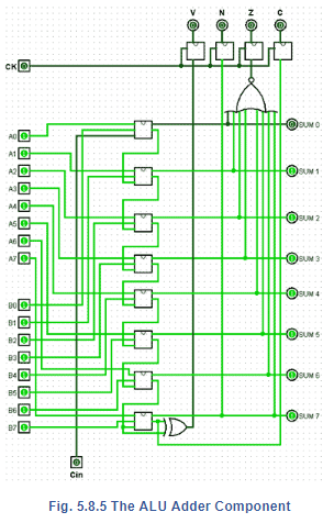
The adder component is an 8-bit ripple carry adder; real ALUs would normally feature a 'carry-look-ahead adder', allowing for high-speed operation. However for this example the much simpler ripple carry adder is adequate, as the operation is totally manual.
The adder component is illustrated in Fig. 5.8.5 and consists of eight full-adder circuits with additional logic consisting of an XOR gate to detect overflow errors, and an 8-input NOR gate to detect a zero result.
Negative result are indicated by sampling the most significant bit of the ‘sum’ output, and a ‘carry’ is indicated by sampling the carry output of the most significant full adder.
Four D type flip- flop are used as ‘flag’ outputs to indicate the current state of the ALU after each operation.
The Shift Register
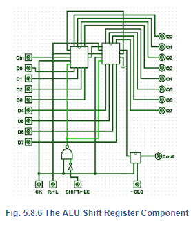
This component uses two 4- bit shift register (from Module 5.7) connected in cascade as shown in Fig. 5.8.6. Inputs are provided for clock pulses, (CK), a right/left shift control (R/~L) and an input to control whether the shift register is in shift, or load-enable modes (SHIFT/~LE).
If ~LE is chosen temporarily during shift operations, the shift register can be reloaded from the data placed on the 8-bit ‘Data A’ and ‘carry-in’ (CIN) inputs. This action is synchronised to the CK pulse by the external NAND and NOT gates connecting the SHIFT/~LE input to the two ~LOAD inputs of the 4-bit shift registers.
An additional JKflip- flop (mimicking a D type flip-flop) is placed between the ‘serial-right’ output of the shift register and COUT to allow the ‘clear carry’ input (~CLC) to clear the carry flag.
|
125 videos|83 docs|58 tests
|
FAQs on 8-Bit Adder - Digital Electronics - Electrical Engineering (EE)
| 1. What is an 8-bit adder? |  |
| 2. How does an 8-bit adder work? | |
| 3. What is the purpose of an 8-bit adder? | |
| 4. What are the inputs and outputs of an 8-bit adder? | |
| 5. Can an 8-bit adder handle numbers larger than 8 bits? | |


practice quizzes
,Previous Year Questions with Solutions
,Important questions
,Exam
,study material
,past year papers
,shortcuts and tricks
,video lectures
,Summary
,ppt
,8-Bit Adder | Digital Electronics - Electrical Engineering (EE)
,Objective type Questions
,Viva Questions
,Free
,8-Bit Adder | Digital Electronics - Electrical Engineering (EE)
,mock tests for examination
,Sample Paper
,Semester Notes
,MCQs
,Extra Questions
,8-Bit Adder | Digital Electronics - Electrical Engineering (EE)
;


8-Bit Adder Free PDF Download
Importance of 8-Bit Adder
8-Bit Adder Notes
8-Bit Adder Electrical Engineering (EE) Questions
Study 8-Bit Adder on the App
|
© EduRev
|
Education Revolution
|


|


