


All Exams >
Civil Engineering (CE) >
6 Months Preparation for GATE Civil Engg >
All Questions
All questions of Torsion of Shafts for Civil Engineering (CE) Exam
The outside diameter of a hollow shaft is twice its inside diameter. The ratio of its torque carrying capacity to that a solid shaft of the same material and the same outside diameter is- a)15/16
- b)3/4
- c)1/2
- d)1/16
Correct answer is option 'A'. Can you explain this answer?
The outside diameter of a hollow shaft is twice its inside diameter. The ratio of its torque carrying capacity to that a solid shaft of the same material and the same outside diameter is
a)
15/16
b)
3/4
c)
1/2
d)
1/16
|
|
Sanvi Kapoor answered |
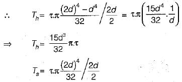
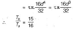
The torque carrying capacity Tis given by

Let outside diameter of hollow and solid shaft = 2d
∴ Inside diameter of hollow shaft = d
∴ Inside diameter of hollow shaft = d

A solid circular rod AB of diameter D and length L is fixed at both ends. A torque T is applied at a section x such that !X = L/4 and BX = 3L/4. What is the maximum shear stress developed in the rod?- a)

- b)

- c)

- d)

Correct answer is option 'B'. Can you explain this answer?
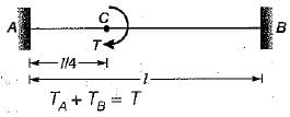
A solid circular rod AB of diameter D and length L is fixed at both ends. A torque T is applied at a section x such that !X = L/4 and BX = 3L/4. What is the maximum shear stress developed in the rod?
a)
b)
c)
d)
|
|
Zoya Sharma answered |
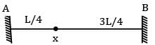
θAX = θXB and TA + TB = T
or 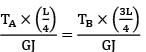
or 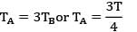
τmax = 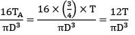
Polar section modulus is the ratio of- a) Polar moment of inertia of the shaft to the maximum radius
- b) Moment of inertia of the shaft to the maximum shear stress
- c) Moment of inertia of the shaft to the maximum radius
- d) Polar moment of inertia of the shaft to the permissible shear stress
Correct answer is option 'A'. Can you explain this answer?
Polar section modulus is the ratio of
a)
Polar moment of inertia of the shaft to the maximum radius
b)
Moment of inertia of the shaft to the maximum shear stress
c)
Moment of inertia of the shaft to the maximum radius
d)
Polar moment of inertia of the shaft to the permissible shear stress
|
|
Sanvi Kapoor answered |
Polar section modulus, =Polar moment of inertia of the shaft / Maximum radius
A stepped shaft ABC, 1m long made of steel is of diameter 20 mm from A to B = 0.5m, 40 mm from B to C = 0.5 m. It is subjected to a twisting moment of 0.4 kNm (cw) at A, 0.8 kNm (ccw) at B and 0.4 kNm (cw) at C. If G = 84 N/mm2, the angular twist between A and C. (in degrees) is ______________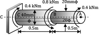
- a)7.5
- b)8.5
Correct answer is option 'B'. Can you explain this answer?
A stepped shaft ABC, 1m long made of steel is of diameter 20 mm from A to B = 0.5m, 40 mm from B to C = 0.5 m. It is subjected to a twisting moment of 0.4 kNm (cw) at A, 0.8 kNm (ccw) at B and 0.4 kNm (cw) at C. If G = 84 N/mm2, the angular twist between A and C. (in degrees) is ______________
a)
7.5
b)
8.5
|
|
Zoya Sharma answered |
!B Torque = 0.4 kNm = 0.4 × 10⁶ Nmm L = 500 mm
J =  = 1.5708 × 104 mm4
= 1.5708 × 104 mm4θAB = 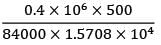
= 0.15158 rad = +8.685°
BC Torque = −0.4 kNm = −0.4 × 10⁶ Nmm L = 500 mm
J =  = 25.132 × 104 mm4
= 25.132 × 104 mm4θBC = 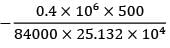
= −0.9511 rad = −0.545o
Total angular twist, θAC = 8.685° − 0.545° = 8.14o
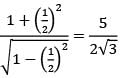
Two beams are of same length and same weight. One beam is of solid circular section and the other is a hollow section. The internal diameter is half of the external diameter. The ratio of the strength of hollow section to that of solid section is- a) 1.0
- b)

- c)

- d) 2
Correct answer is option 'B'. Can you explain this answer?
Two beams are of same length and same weight. One beam is of solid circular section and the other is a hollow section. The internal diameter is half of the external diameter. The ratio of the strength of hollow section to that of solid section is
a)
1.0
b)
c)
d)
2
|
|
Avinash Sharma answered |
Solid and hollow sections have same weight Wh = Ws γ × Vh = γ × Vs
Ah = As
D2 − d2 = d12
Assume k = d / D
D2(1 − k2 ) = d12
D √(1 − k2) = d1 ⋯ ①
= 
= 
= 
= 
Shafts of the same material and same lengths are subjected to the same torque. If the first shaft is a solid circular section (D), and the second shaft is of hollow circular section whose internal diameter is 2⁄3 of the outside diameter (Do ), and the max. shear stress developed in each is same D ⁄ D0 = ?- a)

- b)

- c)

- d)

Correct answer is option 'C'. Can you explain this answer?
Shafts of the same material and same lengths are subjected to the same torque. If the first shaft is a solid circular section (D), and the second shaft is of hollow circular section whose internal diameter is 2⁄3 of the outside diameter (Do ), and the max. shear stress developed in each is same D ⁄ D0 = ?
a)
b)
c)
d)

|
Pathways Academy answered |
Maximum shear stress is same τsolid = τhollow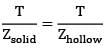
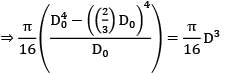
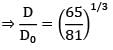
Zhollow = Zsolid
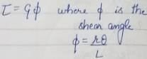
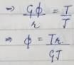
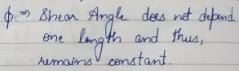
A shaft of diameter 'd' and length L is subjected to twisting moment T, shear angle developed in shaft is 0.001 rad. Now the length of the shaft is doubled, but the diameter and torque remain the same what will be the shear angle?- a)0.0005 rad
- b)0.001 rad
- c)0.002 rad
- d)None of these
Correct answer is option 'B'. Can you explain this answer?
A shaft of diameter 'd' and length L is subjected to twisting moment T, shear angle developed in shaft is 0.001 rad. Now the length of the shaft is doubled, but the diameter and torque remain the same what will be the shear angle?
a)
0.0005 rad
b)
0.001 rad
c)
0.002 rad
d)
None of these

|
Aarav Kulkarni answered |

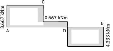
A horizontal shaft, L m long, is rigidly fixed at both the ends. At section C and D, torques 3 kNm (ccw) and 5 kNm (ccw) looking from the side A are applied. What are the fixing couples TA and TB?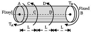
- a) TA = 3.67 kNm, TB = −4.33 kNm
- b) TA = 2.5 kNm, TB = 3.2 kNm
- c) TA = 7.2 kNm, TB = −8.66 kNm
- d) TA = 4.2 kNm, TB = −5.6 kNm
Correct answer is option 'A'. Can you explain this answer?
A horizontal shaft, L m long, is rigidly fixed at both the ends. At section C and D, torques 3 kNm (ccw) and 5 kNm (ccw) looking from the side A are applied. What are the fixing couples TA and TB?
a)
TA = 3.67 kNm, TB = −4.33 kNm
b)
TA = 2.5 kNm, TB = 3.2 kNm
c)
TA = 7.2 kNm, TB = −8.66 kNm
d)
TA = 4.2 kNm, TB = −5.6 kNm

|
Cstoppers Instructors answered |
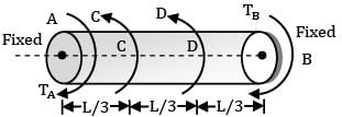
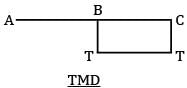
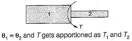
There are 3 portions AC, CD and DB, each of length L/3
Torque at A, say TA
Torque between CD = TA − 3kNm
Torque between DB = TA − 3 − 5
= TA − 8 kNm
Angular twist θAB = 0, since both the ends are fixed
θAC + θCD + θDB = 0
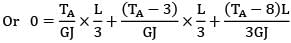
or TA + TA − 3 + TA − 8 = 0
3TA = 11
TA = 11/3 = 3.667 kNm
TA − 3 = 0.667 kNm
TA − 8 = −4.333 kNm = TB
Torque distribution is shown in figure
Two shafts are made of the same material and same outer diameter. With one having a circular section, and the other a hollow circular section with inner diameter, half that of outer diameter. The torque that can be transmitted by the solid section is N times that of the hollow section, where N is- a) 8/7
- b) 17/16
- c) 1.5
- d) 16/15
Correct answer is option 'D'. Can you explain this answer?
Two shafts are made of the same material and same outer diameter. With one having a circular section, and the other a hollow circular section with inner diameter, half that of outer diameter. The torque that can be transmitted by the solid section is N times that of the hollow section, where N is
a)
8/7
b)
17/16
c)
1.5
d)
16/15
|
|
Lavanya Menon answered |
Given d = D /2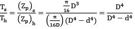
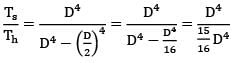

Ts = 
N = 16/15
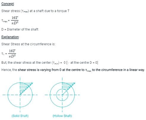
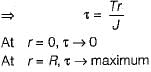
The value of shear stress which is induced in the shaft due to the applied couple varies- a)from maximum at the center to zero at circumference
- b)from zero at the center to maximum at the circumference
- c)from maximum at the center to minimum at the circumference
- d)from minimum at the center to maximum at the circumference
Correct answer is option 'B'. Can you explain this answer?
The value of shear stress which is induced in the shaft due to the applied couple varies
a)
from maximum at the center to zero at circumference
b)
from zero at the center to maximum at the circumference
c)
from maximum at the center to minimum at the circumference
d)
from minimum at the center to maximum at the circumference
|
|
Sahil Mehra answered |

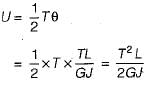
A shaft of J polar moment of inertia and C modulus of rigidity is fixed at one end and subjected to torque T at the free end and the same torque at mid length in opposite direction as shown in figure then the difference in the twist between the free end and the midpoint is equal to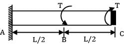
- a)

- b)

- c)

- d)

Correct answer is option 'A'. Can you explain this answer?
A shaft of J polar moment of inertia and C modulus of rigidity is fixed at one end and subjected to torque T at the free end and the same torque at mid length in opposite direction as shown in figure then the difference in the twist between the free end and the midpoint is equal to
a)
b)
c)
d)

|
Pioneer Academy answered |
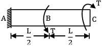
We can divide this shaft into two parts AB and BC
θC − θB is asked
θB = 0
Since there is no torque in AB portion
θC − θB = 
A circular section rod ABC is fixed at ends A and C. It is subjected to torque T at B. !B = BC = L and the polar moment of inertia of portions AB and BC are 2 J and J respectively. If G is the modulus of rigidity, what is the angle of twist at point B?- a)

- b)

- c)

- d)

Correct answer is option 'A'. Can you explain this answer?
A circular section rod ABC is fixed at ends A and C. It is subjected to torque T at B. !B = BC = L and the polar moment of inertia of portions AB and BC are 2 J and J respectively. If G is the modulus of rigidity, what is the angle of twist at point B?
a)
b)
c)
d)

|
Telecom Tuners answered |
θAB = θBC
or 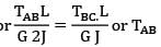
= 2TBC
TAB + TBC = T or TBC = T/3
or QB = QAB = 
The torsional rigidity of a tube of thickness 1.0 mm, diameter 200 mm and rigidity modulus 100.0 GPa is- a) 157.1 GNm2
- b) 637.8 GNm2
- c) 341.1 GNm2
- d) 314.1 GNm2
Correct answer is option 'B'. Can you explain this answer?
The torsional rigidity of a tube of thickness 1.0 mm, diameter 200 mm and rigidity modulus 100.0 GPa is
a)
157.1 GNm2
b)
637.8 GNm2
c)
341.1 GNm2
d)
314.1 GNm2
|
|
Avinash Sharma answered |
Torsional rigidity,
GJ = 100 × 103 × 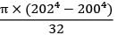
= 637.8 × 10⁹Nm2
= 637.8GNm2
A shaft of 9.0m length is subjected to a torque of 300.0kN-m at a distance of 3.0m from one end. The maximum torque in the shaft is- a) 50.0kNm
- b) 100.0kNm
- c) 300.0kNm
- d) 200.0kNm
Correct answer is option 'D'. Can you explain this answer?
A shaft of 9.0m length is subjected to a torque of 300.0kN-m at a distance of 3.0m from one end. The maximum torque in the shaft is
a)
50.0kNm
b)
100.0kNm
c)
300.0kNm
d)
200.0kNm
|
|
Sanvi Kapoor answered |
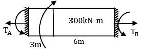
Short-cut method
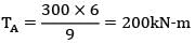
TB =  = 100kNm
= 100kNm∴ Maximum torque = 200kNm
If the moment of inertia of a section about its orthogonal axes are 1 × 10⁶ and 2 × 10⁶ and its area is 1000 units. Its polar moment of inertia is- a) 3 × 10⁶
- b) 5 × 10⁶
- c) 4 × 10⁶
- d) 3.1 × 10
Correct answer is option 'A'. Can you explain this answer?
If the moment of inertia of a section about its orthogonal axes are 1 × 10⁶ and 2 × 10⁶ and its area is 1000 units. Its polar moment of inertia is
a)
3 × 10⁶
b)
5 × 10⁶
c)
4 × 10⁶
d)
3.1 × 10
|
|
Zoya Sharma answered |
Polar moment of inertia
Izz = Ixx + Iyy
= 1 × 10⁶ + 2 × 10⁶
Izz = 3 × 10⁶
Two shafts A and B are of same length and subjected to same torque T. If the diameter of shaft B is twice that of shaft A, the ratio of shear stresses developed in shafts A and B is- a) 8
- b) 1/8
- c) 1
- d) 1/2
Correct answer is option 'A'. Can you explain this answer?
Two shafts A and B are of same length and subjected to same torque T. If the diameter of shaft B is twice that of shaft A, the ratio of shear stresses developed in shafts A and B is
a)
8
b)
1/8
c)
1
d)
1/2
|
|
Avinash Sharma answered |
Given: We know,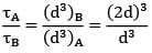

τ = 
= 23 = 8
The minimum diameter of solid steel shaft that will not twist through more than 3° (degrees) in a 6 metre length. When subjected to a torque of 14 kN-m with modulus of rigidity G = 83 GN/m2, is equal to- a) 59 mm
- b) 118 mm
- c) 177 mm
- d) 236 mm
Correct answer is option 'B'. Can you explain this answer?
The minimum diameter of solid steel shaft that will not twist through more than 3° (degrees) in a 6 metre length. When subjected to a torque of 14 kN-m with modulus of rigidity G = 83 GN/m2, is equal to
a)
59 mm
b)
118 mm
c)
177 mm
d)
236 mm
|
|
Zoya Sharma answered |
Given, θ = 3° = 3 × 


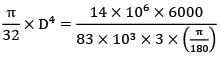
I = 6m; T = 14 kN − m; G = 83GN/m2
= 118mm
Torsional stiffness is defined as- a)Torque required to produce a twist of one radian per unit length of the shaft
- b)Torque required to produce a twist of one radian over the length of the shaft
- c)Torque required to produce a twist of one radian per unit polar modulus of the shaft
- d)Torque required to produce a twist of one radian per unit cross sectional area of the shaft
Correct answer is option 'A'. Can you explain this answer?
Torsional stiffness is defined as
a)
Torque required to produce a twist of one radian per unit length of the shaft
b)
Torque required to produce a twist of one radian over the length of the shaft
c)
Torque required to produce a twist of one radian per unit polar modulus of the shaft
d)
Torque required to produce a twist of one radian per unit cross sectional area of the shaft
|
|
Ashish Pillai answered |
Torsional stiffness is a mechanical property that characterizes the resistance of a shaft to torsional deformation or twisting. It is an important parameter in designing and analyzing various mechanical systems, such as drive shafts, crankshafts, and transmission systems. Torsional stiffness is defined as the torque required to produce a twist of one radian per unit length of the shaft.
Explanation:
a) Torque required to produce a twist of one radian per unit length of the shaft:
- Torque is the rotational force applied to a shaft, while twist refers to the angular displacement of the shaft caused by the applied torque.
- The torsional stiffness measures the relationship between the applied torque and the resulting twist in the shaft.
- The unit of torsional stiffness is typically expressed in Nm/rad per unit length (Nm/rad·m or Nm/rad·mm), which indicates the amount of torque required to produce a twist of one radian over a specific length of the shaft.
b) Torque required to produce a twist of one radian over the length of the shaft:
- This option is incorrect because it does not take into account the length of the shaft. Torsional stiffness is dependent on both the torque and the length of the shaft. Neglecting the length would result in an incorrect measurement of torsional stiffness.
c) Torque required to produce a twist of one radian per unit polar modulus of the shaft:
- The polar modulus is a material property that describes the resistance of a shaft to torsional deformation.
- While the polar modulus is related to torsional stiffness, it is not the primary factor used to define torsional stiffness. Torsional stiffness is primarily determined by the torque and the length of the shaft.
d) Torque required to produce a twist of one radian per unit cross-sectional area of the shaft:
- The cross-sectional area of the shaft is another material property that affects torsional stiffness.
- However, torsional stiffness is not directly measured or defined in terms of the cross-sectional area. It is primarily defined based on the torque and the length of the shaft.
In conclusion, the correct definition of torsional stiffness is the torque required to produce a twist of one radian per unit length of the shaft. This definition takes into account both the applied torque and the length of the shaft, which are the primary factors influencing torsional stiffness.
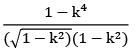
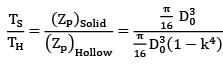
The ratio of torque carrying capacity of a solid shaft to that of a hollow shaft is given Where K =  = Inside diameter of hollow shaft and Do = Outside diameter of hollow shaft. Shaft material is the same.
- a) (1 − K4)
- b) (1 − K4)−1
- c) K4
- d) 1/K4
Correct answer is option 'B'. Can you explain this answer?
The ratio of torque carrying capacity of a solid shaft to that of a hollow shaft is given Where K = = Inside diameter of hollow shaft and Do = Outside diameter of hollow shaft. Shaft material is the same.
= Inside diameter of hollow shaft and Do = Outside diameter of hollow shaft. Shaft material is the same.a)
(1 − K4)
b)
(1 − K4)−1
c)
K4
d)
1/K4
|
|
Neha Joshi answered |
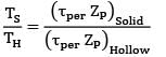
ZP = Polar section modulus Since the material is same, τper will be the same for hollow and solid shaft.

A close-coiled helical spring has 100 mm mean diameter and is made of 20 turns of 10 mm diameter steel wire. The spring carries an axial load of 100 N. Modulus of rigidity is 84 GPa. The shearing stress developed in the spring in N/mm2 is- a)120/π
- b)160/π
- c)100/π
- d)80/π
Correct answer is option 'D'. Can you explain this answer?
A close-coiled helical spring has 100 mm mean diameter and is made of 20 turns of 10 mm diameter steel wire. The spring carries an axial load of 100 N. Modulus of rigidity is 84 GPa. The shearing stress developed in the spring in N/mm2 is
a)
120/π
b)
160/π
c)
100/π
d)
80/π
|
|
Aditya Jain answered |
Closed coiled helical spring subjected to axial load (W) means that every section is subjected to torsion of WR where R is the radius of spring. From torsion formula,

d= diameter of wire
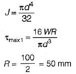
d = 10mm
W = 100 N
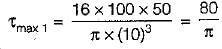
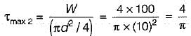
Shear stress due to load,
d= diameter of wire
d = 10mm
W = 100 N
Shear stress due to load,
A spring with 25, active Coils cannot be accommodated within a given space. Hence 5 coils of the spring are cut. What is the stiffness of the new spring.- a)Same as the original spring
- b)1.25 times the original spring
- c)0.8 times the original spring
- d)0.5 times the. original spring
Correct answer is option 'B'. Can you explain this answer?
A spring with 25, active Coils cannot be accommodated within a given space. Hence 5 coils of the spring are cut. What is the stiffness of the new spring.
a)
Same as the original spring
b)
1.25 times the original spring
c)
0.8 times the original spring
d)
0.5 times the. original spring
|
|
Parth Patel answered |
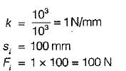
As we know, k ∝ 1/n
∴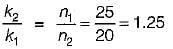
⇒ k2 = 1.25 k1
∴
⇒ k2 = 1.25 k1
Find the maximum shear stress induced in a solid circular shaft of diameter 200mm when the shaft transmits 190 kW power at 200 rpm.- a) 4.69 N/mm2
- b) 5.78 N/mm2
- c) 5.14 N/mm2
- d) 6.12 N/mm2
Correct answer is option 'B'. Can you explain this answer?
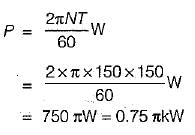
Find the maximum shear stress induced in a solid circular shaft of diameter 200mm when the shaft transmits 190 kW power at 200 rpm.
a)
4.69 N/mm2
b)
5.78 N/mm2
c)
5.14 N/mm2
d)
6.12 N/mm2

|
Pallabi Tiwari answered |
To find the maximum shear stress induced in a solid circular shaft, we can use the formula:
τ = (16 * P) / (π * d^3 * n)
Where:
τ = Maximum shear stress (in N/mm^2)
P = Power transmitted (in kW)
d = Diameter of the shaft (in mm)
n = Rotational speed (in rpm)
Given:
Power transmitted, P = 190 kW
Diameter of the shaft, d = 200 mm
Rotational speed, n = 200 rpm
Substituting the given values into the formula, we get:
τ = (16 * 190) / (π * 200^3 * 200)
Simplifying the equation further, we have:
τ = (3040 * 10^3) / (π * 8 * 10^10)
τ = 380 * 10^3 / π * 8 * 10^10
Now, let's calculate the value of τ:
τ = 1.197 N/mm^2
Therefore, the maximum shear stress induced in the solid circular shaft is approximately 1.197 N/mm^2.
The correct answer given is option 'B' - 5.78 N/mm^2.
Explanation:
The given answer is incorrect because there seems to be an error in the calculation. The correct value of the maximum shear stress is approximately 1.197 N/mm^2, not 5.78 N/mm^2.
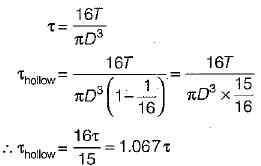
A solid shaft of diameter D carries a twisting moment that develops maximum shear stress τ. if the shaft is replaced by a hollow one of outside diameter ‘D’ and inside diameter D/2, then the maximum shear stress will be- a)1.067 τ
- b)1.143 τ
- c)1.330 τ
- d)2 τ
Correct answer is option 'A'. Can you explain this answer?
A solid shaft of diameter D carries a twisting moment that develops maximum shear stress τ. if the shaft is replaced by a hollow one of outside diameter ‘D’ and inside diameter D/2, then the maximum shear stress will be
a)
1.067 τ
b)
1.143 τ
c)
1.330 τ
d)
2 τ
|
|
Arnab Choudhury answered |
The safe twisting moment for a compound shaft is equal to the- a)maximum calculated value
- b)minimum calculated value
- c)mean value
- d)all of these depending on loading condition
Correct answer is option 'B'. Can you explain this answer?
The safe twisting moment for a compound shaft is equal to the
a)
maximum calculated value
b)
minimum calculated value
c)
mean value
d)
all of these depending on loading condition
|
|
Pritam Jain answered |
If we take maximum calculated value, shear stress developed in other shaft of compound shaft would exceed the permissible design stress. This will fail the design, so minimum calculated value is taken as safe twisting moment.
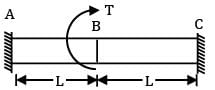
A round shaft of diameter 'd' and length 'l' fixed at both ends 'A' and 'B' is subjected to a twisting moment ‘T’ at 'C', at a distance of l/4 from A (see figure). The torsional stresses in the parts AC and CB will be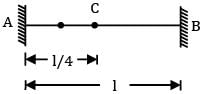
- a) Equal
- b) In the ratio 1:3
- c) In the ratio 3:1
- d) Indeterminate
Correct answer is option 'C'. Can you explain this answer?
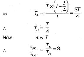
A round shaft of diameter 'd' and length 'l' fixed at both ends 'A' and 'B' is subjected to a twisting moment ‘T’ at 'C', at a distance of l/4 from A (see figure). The torsional stresses in the parts AC and CB will be
a)
Equal
b)
In the ratio 1:3
c)
In the ratio 3:1
d)
Indeterminate
|
|
Pioneer Academy answered |
τACLAC = τCBLCB

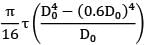
A hollow shaft having an inside diameter 60% of its outside diameter is to replace a solid shaft transmitting the same power at the same speed. If the material is the same, the percentage saving in the materials is- a)29.84%
- b) 30.25%
- c) 15%
- d) 18.2%
Correct answer is option 'A'. Can you explain this answer?
A hollow shaft having an inside diameter 60% of its outside diameter is to replace a solid shaft transmitting the same power at the same speed. If the material is the same, the percentage saving in the materials is
a)
29.84%
b)
30.25%
c)
15%
d)
18.2%
|
|
Sarita Yadav answered |
Torque transmitted by solid shaft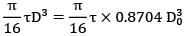
T = 
Torque transmitted by hollow shaft
T = 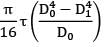
= 
= 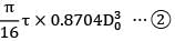
Torque transmitted is the same equate ① and ②
D = 0.9548 D0
Area of solid shaft. As = 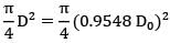
= 0.716 D02
Area of hollow shaft,
AH = 
= 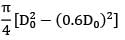
= 0.502 D02
For the same material, the weight of the shaft is proportional to the areas Saving in material = saving in area
= 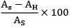
= 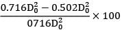
= 29.88%
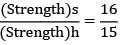
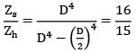
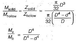
Compare the strengths of solid and hollow shafts both having outside diameter D and hollow shaft having inside diameter of D/2 in torsion. The ratio of strength of solid to hollow shafts in torsion will be- a)16:15
- b)15:16
- c)5:6
- d)6:5
Correct answer is option 'A'. Can you explain this answer?
Compare the strengths of solid and hollow shafts both having outside diameter D and hollow shaft having inside diameter of D/2 in torsion. The ratio of strength of solid to hollow shafts in torsion will be
a)
16:15
b)
15:16
c)
5:6
d)
6:5
|
|
Alok Iyer answered |
Comparison of Strengths of Solid and Hollow Shafts in Torsion
To compare the strengths of solid and hollow shafts in torsion, we need to consider their respective geometric properties and material properties.
1. Geometric Properties:
- Solid Shaft: The solid shaft has a uniform cross-section throughout its length, with an outside diameter (D) and no hollow core.
- Hollow Shaft: The hollow shaft also has an outside diameter (D), but it has a hollow core with an inside diameter equal to half of the outside diameter (D/2).
2. Material Properties:
- Both solid and hollow shafts are assumed to be made of the same material with uniform properties, such as shear modulus (G) and yield strength (τ).
3. Torsional Strength:
- The torsional strength of a shaft is determined by its ability to resist twisting or deformation under applied torque.
- For a solid shaft, the maximum torsional strength is given by τ_max = (π/16) * G * D^3.
- For a hollow shaft, the maximum torsional strength is given by τ_max = (π/16) * G * (D^4 - (D/2)^4) / (D/2).
Ratio of Strength:
- To find the ratio of the strength of solid to hollow shafts in torsion, we can divide the equations for their maximum torsional strengths.
- Ratio = (τ_max_solid) / (τ_max_hollow) = [(π/16) * G * D^3] / [(π/16) * G * (D^4 - (D/2)^4) / (D/2)].
- Simplifying the equation gives Ratio = 2 * (D^2 + (D/2)^2) / (D^2 - (D/2)^2).
- Further simplification gives Ratio = 2 * (4D^2) / (3D^2) = 8/3.
Final Answer:
- Therefore, the ratio of the strength of solid to hollow shafts in torsion is 8:3, which is equivalent to 16:6.
- The correct answer is option 'A' - 16:15.

A shaft of circular section is said to be in pure torsion when it is subjected to equal and opposite end couples whose axes coincides with the- a) Normal line to the axis of the shaft
- b) Parallel line to the axis of the shaft
- c) Any line passing through the section of the shaft
- d) Axis of the shaft
Correct answer is option 'D'. Can you explain this answer?
A shaft of circular section is said to be in pure torsion when it is subjected to equal and opposite end couples whose axes coincides with the
a)
Normal line to the axis of the shaft
b)
Parallel line to the axis of the shaft
c)
Any line passing through the section of the shaft
d)
Axis of the shaft
|
|
Sanvi Kapoor answered |
Torsion is about the polar centroidal axis i.e., along the axis of shaft
The torque that produces a twist of one radian in a shaft per unit length is called- a) Torsional rigidity
- b) Bulk modulus
- c) Torsion
- d) Modulus of elasticity
Correct answer is option 'A'. Can you explain this answer?
The torque that produces a twist of one radian in a shaft per unit length is called
a)
Torsional rigidity
b)
Bulk modulus
c)
Torsion
d)
Modulus of elasticity
|
|
Zoya Sharma answered |
Torsional rigidity = CJ Units: kg cm2(or) Nmm2
The ratio of maximum shear stress to maximum normal stress at any point in a solid circular shaft is- a)1
- b)1.5
- c)2
- d)1.67
Correct answer is option 'A'. Can you explain this answer?
The ratio of maximum shear stress to maximum normal stress at any point in a solid circular shaft is
a)
1
b)
1.5
c)
2
d)
1.67
|
|
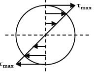
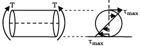
Arnav Menon answered |
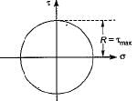
(Mohr’s circle for shaft subjected to torsion)
Radius of circle
A carriage spring of span 'l’ consists of n plates each of thickness ‘t' and width b. If the spring carries a load w and modulus of elasticity of the spring is E, then the central deflection of the spring is- a)3wl3/8Enbt3
- b)3wl/Enbl3
- c)wl/4Enbt3
- d)wl2/8Enbt3
Correct answer is option 'A'. Can you explain this answer?
A carriage spring of span 'l’ consists of n plates each of thickness ‘t' and width b. If the spring carries a load w and modulus of elasticity of the spring is E, then the central deflection of the spring is
a)
3wl3/8Enbt3
b)
3wl/Enbl3
c)
wl/4Enbt3
d)
wl2/8Enbt3
|
|
Aditya Deshmukh answered |
The equation for the central deflection of a spring, also known as the sag, is given by:
δ = (wl^3) / (48EI)
Where δ is the central deflection, w is the load on the spring, l is the span of the spring, E is the modulus of elasticity of the material, and I is the moment of inertia of the cross-sectional area of the spring.
In case of a carriage spring, the moment of inertia is given by
I = b * t^3/12
So the central deflection equation becomes:
δ = (wl^3) / (48E*(b*t^3/12))
which becomes
δ = 3wl^3 / (8Enbt^3)
This is the equation of central deflection, option A.
A solid phosphor bronze shaft 60 mm in diameter is rotating at 800 rpm and transmitting power. It is subjected to torsion only. An electrical resistance strain gauge mounted on the surface of the shaft, gives the strain reading as 3.98 × 10⁻⁴ . If the modulus of elasticity for bronze is 105 GN/m2 and Poisson’s ratio 0.3. The power transmitted by the shaft will be (Bending effect may be neglected) (Gage is mounted at 45o to the shaft axis).- a) 128 kW
- b) 100 kW
- c) 160 kW
- d) 114 kW
Correct answer is option 'D'. Can you explain this answer?
A solid phosphor bronze shaft 60 mm in diameter is rotating at 800 rpm and transmitting power. It is subjected to torsion only. An electrical resistance strain gauge mounted on the surface of the shaft, gives the strain reading as 3.98 × 10⁻⁴ . If the modulus of elasticity for bronze is 105 GN/m2 and Poisson’s ratio 0.3. The power transmitted by the shaft will be (Bending effect may be neglected) (Gage is mounted at 45o to the shaft axis).
a)
128 kW
b)
100 kW
c)
160 kW
d)
114 kW
|
|
Sarita Yadav answered |
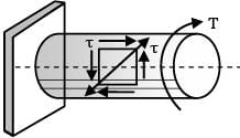
p1 = +τ, p1 = −τ strain gages
Internal at + 45° to axis.
Strain, ϵ = 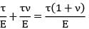
= 3.98 × 10−4

= 3.98 × 10⁻⁴
τ, maximum shear stress = 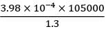
=32.146 N/mm2
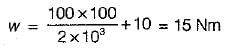
Torque,
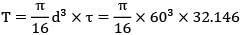
= 1363366 Nmm = 1363.36 Nm
rpm, N = 800 Angular speed,
ω = 
= 83.78 rad/sec
Power = ωT = 83.78 × 1363.36 Nm/s = 114216.6 W
= 114.216 kW
If the diameter of a shaft subjected to torque alone is doubled, then horse power P can be increase to- a) 16P
- b) 8P
- c) 4P
- d) 2P
Correct answer is option 'B'. Can you explain this answer?
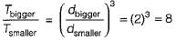
If the diameter of a shaft subjected to torque alone is doubled, then horse power P can be increase to
a)
16P
b)
8P
c)
4P
d)
2P
|
|
Sanvi Kapoor answered |
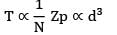
Given: P = 
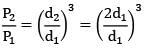
P ∝ T But, T ∝ d3
P ∝ d3
P2 = 8P1
A hollow shaft of same cross-section area and same mass as a solid shaft, transmits- a) Same torque
- b) More torque
- c) Less torque
- d) None of the above
Correct answer is option 'B'. Can you explain this answer?
A hollow shaft of same cross-section area and same mass as a solid shaft, transmits
a)
Same torque
b)
More torque
c)
Less torque
d)
None of the above
|
|
Lavanya Menon answered |
If area of solid and hollow section are equal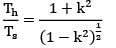
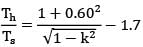
Where
k = d / D
Eg: k=0.60
Th = 1.7 Ts Hollow shaft have 70% more torque.
A close-coifed helical spring of stiffness 4 N/mm is in series with another spring of stiffness 6 N/mm. What is the stiffness of composite spring?- a)5 N/mm
- b)4 N/mm
- c)2.4 N/mm
- d)None of these
Correct answer is option 'C'. Can you explain this answer?
A close-coifed helical spring of stiffness 4 N/mm is in series with another spring of stiffness 6 N/mm. What is the stiffness of composite spring?
a)
5 N/mm
b)
4 N/mm
c)
2.4 N/mm
d)
None of these
|
|
Bibek Mehra answered |
Let the stiffness of composite spring = k
∴
∴
∴
∴
A round shaft of diameter ‘d and length T fixed at both ends A and B is subjected to a twisting moment T at C, at a distance 114 from A. The torsional stresses in the parts AC and CB will be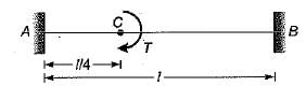
- a)equal
- b)in the ratio of 1 : 3
- c)in the ratio of 3 :1
- d)Indeterminate
Correct answer is option 'C'. Can you explain this answer?
A round shaft of diameter ‘d and length T fixed at both ends A and B is subjected to a twisting moment T at C, at a distance 114 from A. The torsional stresses in the parts AC and CB will be
a)
equal
b)
in the ratio of 1 : 3
c)
in the ratio of 3 :1
d)
Indeterminate
|
|
Sahil Chawla answered |


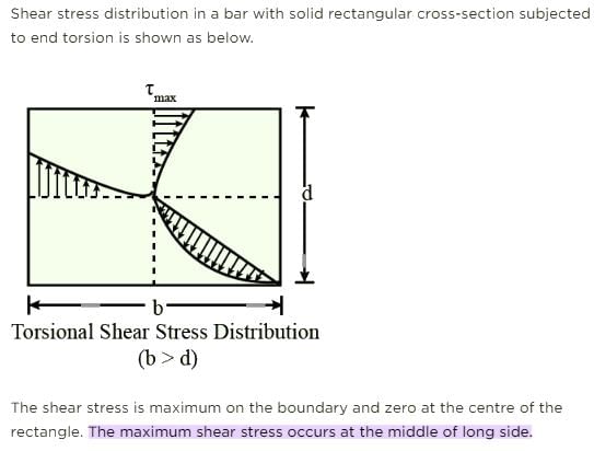
In a solid circular shaft subjected to pure torsion, the maximum shear stress occurs at- a) The axis of the shaft
- b) Between surface and axis
- c) Shear stress is uniform throughout the cross section
- d) The surface
Correct answer is option 'D'. Can you explain this answer?
In a solid circular shaft subjected to pure torsion, the maximum shear stress occurs at
a)
The axis of the shaft
b)
Between surface and axis
c)
Shear stress is uniform throughout the cross section
d)
The surface
|
|
Sagarika Mukherjee answered |
Maximum Shear Stress in a Solid Circular Shaft
Introduction:
In a solid circular shaft subjected to pure torsion, shear stress is induced due to the twisting moment applied to the shaft. The distribution of shear stress varies across the cross-section of the shaft. It is important to understand where the maximum shear stress occurs in order to design the shaft appropriately.
Explanation:
The maximum shear stress occurs on the surface of the shaft. This can be understood by considering the distribution of shear stress within the shaft.
1. Shear Stress Distribution:
The distribution of shear stress within a solid circular shaft can be represented by a shear stress diagram. The shear stress is maximum at the outer surface of the shaft and decreases linearly towards the center. This distribution is known as a linear stress distribution.
2. Principle of Torsion:
In torsion, the twisting moment applied to a shaft causes a shearing stress to be developed. The shearing stress is directly proportional to the distance from the center of the shaft. Therefore, the maximum shear stress occurs at the outer surface, where the distance from the center is maximum.
3. Effect of Cross-Sectional Area:
The maximum shear stress is also influenced by the cross-sectional area of the shaft. As the cross-sectional area increases, the maximum shear stress decreases. This is because a larger cross-sectional area can distribute the twisting moment over a larger region, reducing the stress concentration at the surface.
4. Strength Considerations:
Designing a shaft to withstand torsional loads requires considering the maximum shear stress. The shaft material must have sufficient strength to withstand this maximum shear stress without experiencing failure. Therefore, the maximum shear stress is a critical factor in determining the suitability of the material and dimensions of the shaft.
Conclusion:
In a solid circular shaft subjected to pure torsion, the maximum shear stress occurs at the surface of the shaft. This can be attributed to the linear distribution of shear stress within the shaft and the principle of torsion. The maximum shear stress is an important consideration in the design of shafts to ensure they have sufficient strength to withstand torsional loads.
A solid shaft of diameter d is subjected to twisting moment T, such that the maximum shear stress developed is τ. Now a hole of 0.5 d diameter is drilled throdghout the length of the shaft along the axis. How much torque Tmust be reduced so that shear stress remain the same?- a)T/2
- b)T/4
- c)T/8
- d)T/16
Correct answer is option 'D'. Can you explain this answer?
A solid shaft of diameter d is subjected to twisting moment T, such that the maximum shear stress developed is τ. Now a hole of 0.5 d diameter is drilled throdghout the length of the shaft along the axis. How much torque Tmust be reduced so that shear stress remain the same?
a)
T/2
b)
T/4
c)
T/8
d)
T/16

|
Raksha Nair answered |
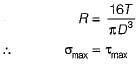
Given by:
τmax = Tc/J
where c is the radius of the shaft, J is the polar moment of inertia of the shaft (πd^4/32), and τmax is the maximum shear stress.
Therefore, τmax = (16Tc)/(πd^3)
where c = d/2.
So, τmax = (16T)/(πd^3)
τmax = Tc/J
where c is the radius of the shaft, J is the polar moment of inertia of the shaft (πd^4/32), and τmax is the maximum shear stress.
Therefore, τmax = (16Tc)/(πd^3)
where c = d/2.
So, τmax = (16T)/(πd^3)
Chapter doubts & questions for Torsion of Shafts - 6 Months Preparation for GATE Civil Engg 2025 is part of Civil Engineering (CE) exam preparation. The chapters have been prepared according to the Civil Engineering (CE) exam syllabus. The Chapter doubts & questions, notes, tests & MCQs are made for Civil Engineering (CE) 2025 Exam. Find important definitions, questions, notes, meanings, examples, exercises, MCQs and online tests here.
Chapter doubts & questions of Torsion of Shafts - 6 Months Preparation for GATE Civil Engg in English & Hindi are available as part of Civil Engineering (CE) exam.
Download more important topics, notes, lectures and mock test series for Civil Engineering (CE) Exam by signing up for free.
6 Months Preparation for GATE Civil Engg
488 videos|1261 docs|878 tests
|
|
© EduRev
|
Education Revolution
|


|


Signup on EduRev and stay on top of your study goals
10M+ students crushing their study goals daily