


All Exams >
Civil Engineering (CE) >
6 Months Preparation for GATE Civil Engg >
All Questions
All questions of Theories of Failure for Civil Engineering (CE) Exam

The principal stresses at a point in a critical - section of a machine component are σ1 = 60 MPa, σ2 = 5 MPa and σ3 = – 40 MPa. For the material of the component, the tensile yield strength is σy = 200 MPa. According to the maximum shear stress theory, the factor of safety is
- a)1.67
- b)3.6
- c)4
- d)2
Correct answer is option 'D'. Can you explain this answer?
The principal stresses at a point in a critical - section of a machine component are σ1 = 60 MPa, σ2 = 5 MPa and σ3 = – 40 MPa. For the material of the component, the tensile yield strength is σy = 200 MPa. According to the maximum shear stress theory, the factor of safety is
a)
1.67
b)
3.6
c)
4
d)
2

|
Pallabi Tiwari answered |

According to principal stress theory, which option represents the correct relation between yield strength in shear (YSS) and the yield strength in tension (YST)?- a)YSS=0.5YST
- b)YSS=0.577YST
- c)YST=0.5YSS
- d)YST=0.577YSS
Correct answer is option 'A'. Can you explain this answer?
According to principal stress theory, which option represents the correct relation between yield strength in shear (YSS) and the yield strength in tension (YST)?
a)
YSS=0.5YST
b)
YSS=0.577YST
c)
YST=0.5YSS
d)
YST=0.577YSS
|
|
Ashutosh Sharma answered |
Explanation: Shear diagonal is at 45’ and by equation of shear stress theory, the required relation is obtained.
Pitting occurs on _____ of the component. - a)Surface
- b)Inner body
- c)Inside or on surface
Correct answer is option 'A'. Can you explain this answer?
Pitting occurs on _____ of the component.
a)
Surface
b)
Inner body
c)
Inside or on surface
|
|
Amrita Chauhan answered |
Explanation: Pitting is a process in which small holes occur on a surface of component.
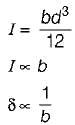
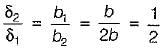
A cantilever beam rectangular in cross-section is subjected to an isolated load at its free end. If the width of the beam is doubled, the deflection of the free end will be changed in the ratio of- a)8
- b)1/8
- c)1/2
- d)2
Correct answer is option 'C'. Can you explain this answer?
A cantilever beam rectangular in cross-section is subjected to an isolated load at its free end. If the width of the beam is doubled, the deflection of the free end will be changed in the ratio of
a)
8
b)
1/8
c)
1/2
d)
2
|
|
Lakshmi Datta answered |
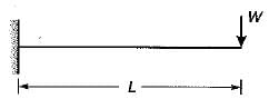
initial width, b1 = b
final width, b2 = 2b
Deflection,

But
All the theories of failure, will give nearly the same result when- a)when one of the principal stresses at a point is large in comparison to the other
- b)when shear stresses act
- c)when both the principal stresses are numerically equal
- d)For all situations of stress
Correct answer is option 'A'. Can you explain this answer?
All the theories of failure, will give nearly the same result when
a)
when one of the principal stresses at a point is large in comparison to the other
b)
when shear stresses act
c)
when both the principal stresses are numerically equal
d)
For all situations of stress
|
|
Shraddha Datta answered |
When one of the principal stresses at a point is large in comparison to the other, the situation resembles uniaxial tension test. Therefore all theories give nearly the same results.
Principal stresses at a point in an elastic materia! are 100 MPa tensile 5 and 50 MPa tensile. Whal is the factor of safety against failure based on maximum shear strain energy theory? The elastic limit in simple tension is 173.2 MPa and Poisson’s ratio 0.3.- a)1.25
- b)1.78
- c)2
- d)2.39
Correct answer is option 'C'. Can you explain this answer?
Principal stresses at a point in an elastic materia! are 100 MPa tensile 5 and 50 MPa tensile. Whal is the factor of safety against failure based on maximum shear strain energy theory? The elastic limit in simple tension is 173.2 MPa and Poisson’s ratio 0.3.
a)
1.25
b)
1.78
c)
2
d)
2.39
|
|
Muskaan Sen answered |
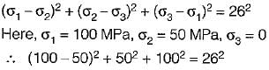
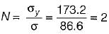
∴
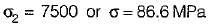
Factor of safety,
Permissible bending moment in a circular shaft under pure bending is M, according to maximum principal stress theory of failure. According to maximum shear theory of failure, the permissible bending moment in the shaft is- a)M/2
- b)M
- c)

- d)2 M
Correct answer is option 'B'. Can you explain this answer?
Permissible bending moment in a circular shaft under pure bending is M, according to maximum principal stress theory of failure. According to maximum shear theory of failure, the permissible bending moment in the shaft is
a)
M/2
b)
M
c)
d)
2 M

|
Hiral Sharma answered |
According to maximum principal stress theory,
σ1 = σy
According to maximum shear stress theory,

Under pure bending,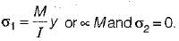
Therefore, in both the cases, permissible bending moment is M,
σ1 = σy
According to maximum shear stress theory,
Under pure bending,
Therefore, in both the cases, permissible bending moment is M,
In a 2D stress system, the two principal stress are p1 = 180 N/mm2 (tensile) and p2 (compressive). For the materials, yield stress in simple tension and compression is 240 N/mm2 and Poisson’s ratio is 0.25. According to maximum normal strain theory for what value of p2 shall yielding commence?- a)240 N/mm2
- b)180 N/mm2
- c)195 N/mm2
- d)200 N/mm2
Correct answer is option 'C'. Can you explain this answer?
In a 2D stress system, the two principal stress are p1 = 180 N/mm2 (tensile) and p2 (compressive). For the materials, yield stress in simple tension and compression is 240 N/mm2 and Poisson’s ratio is 0.25. According to maximum normal strain theory for what value of p2 shall yielding commence?
a)
240 N/mm2
b)
180 N/mm2
c)
195 N/mm2
d)
200 N/mm2
|
|
Sankar Dasgupta answered |
Yielding may occur either in tension or compression.
For yielding in tension,
According to normal strain theory,
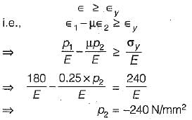
For yielding in compression,
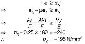
For yielding in tension,
According to normal strain theory,
For yielding in compression,
Buckling is elastic instability which leads to sudden large lateral deflection.- a)True
- b)False
Correct answer is option 'A'. Can you explain this answer?
Buckling is elastic instability which leads to sudden large lateral deflection.
a)
True
b)
False

|
Athul Das answered |
Buckling is a phenomenon that occurs in structural elements when they are subjected to compressive loads. It is an elastic instability that leads to sudden large lateral deflection. When a structural member, such as a column or a beam, is subjected to a compressive load, it experiences a tendency to buckle or buckle out of its original shape. This is due to the fact that the compressive load causes the member to deform, and if the load is large enough, the member will no longer be able to support the load and it will buckle.
Buckling can occur in various types of structures, including columns, beams, plates, shells, and even thin-walled structures like pipes and tubes. The critical load at which buckling occurs is known as the buckling load or the critical buckling load. It is the maximum load that the structure can support without buckling.
Buckling can be classified into different modes, depending on the geometry and boundary conditions of the structure. Some common buckling modes include:
1. Euler Buckling: This is the most basic form of buckling and occurs when a long, slender column is subjected to an axial compressive load. The buckling mode is characterized by a uniform deflection of the column along its length.
2. Lateral-Torsional Buckling: This type of buckling occurs in beams that are subjected to combined bending and axial compressive loads. It is characterized by a combination of lateral deflection and twisting of the beam.
3. Local Buckling: Local buckling occurs in thin-walled structures, such as plates and shells, where certain regions of the structure undergo buckling while the rest of the structure remains unaffected.
Buckling is a critical design consideration in many engineering applications. It is important to understand the buckling behavior of structural elements in order to ensure their stability and safety. Designers and engineers use various methods and techniques, such as the Euler buckling equation, finite element analysis, and experimental testing, to predict and prevent buckling in structures.
In conclusion, buckling is an elastic instability that occurs when a structural element is subjected to compressive loads. It leads to sudden large lateral deflection and can occur in various types of structures. Understanding and predicting buckling behavior is crucial for the safe and efficient design of structural elements.
As per the elastic theory of design, the factor of safety is the ratio of- a)working stress to stress at the limit of proportionality
- b)yield stress to working stress
- c)ultimate stress to working stress
- d)ultimate load to load at yield
Correct answer is option 'B'. Can you explain this answer?
As per the elastic theory of design, the factor of safety is the ratio of
a)
working stress to stress at the limit of proportionality
b)
yield stress to working stress
c)
ultimate stress to working stress
d)
ultimate load to load at yield
|
|
Subhankar Khanna answered |
Usually ratio of ultimate stress to working stress is called factor of safety. In elastic theory of design the material factor of safety is only considered and the ratio of yield stress to working stress is called factor of safety.
In a structural member, there are perpendicular tensile stresses of 100 N/mm2 and 50 N/mm2. What is the equivalent stress in simple tension, according to the maximum principal strain theory? (Poisson’s ratio = 0.25)- a)Zero
- b)87.5 N/mm2
- c)50 N/mm2
- d)100 N/mm2
Correct answer is option 'B'. Can you explain this answer?
In a structural member, there are perpendicular tensile stresses of 100 N/mm2 and 50 N/mm2. What is the equivalent stress in simple tension, according to the maximum principal strain theory? (Poisson’s ratio = 0.25)
a)
Zero
b)
87.5 N/mm2
c)
50 N/mm2
d)
100 N/mm2
|
|
Alok Iyer answered |
Equivalent stress
= σ1 - μσ2
= 100 - 0.25 x 50 = 87.5 N/mm2
= σ1 - μσ2
= 100 - 0.25 x 50 = 87.5 N/mm2
A mechanical component may fail as a result of which of the following
- a)elastic deflection
- b)general yielding
- c)fracture
- d)each of the mentioned
Correct answer is option 'D'. Can you explain this answer?
A mechanical component may fail as a result of which of the following
a)
elastic deflection
b)
general yielding
c)
fracture
d)
each of the mentioned
|
|
Isha Nambiar answered |
Explanation: Failing simply means unable to perform its function satisfactorily.
Type of load affects factor of safety.- a)True
- b)False
Correct answer is option 'A'. Can you explain this answer?
Type of load affects factor of safety.
a)
True
b)
False
|
|
Ishaan Malik answered |
Explanation: Dynamic load has higher factor of safety as compared to static loading.
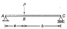
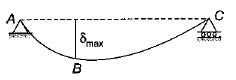
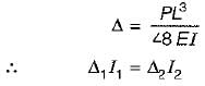
A beam 3 meters in length is simply supported at its ends and carries a point load W at its center. If the slope at the ends is not to exceed 1 °(0.01745 radian), the limiting deflection at the center of beam would be- a)8.75 mm
- b)17.5 mm
- c)26.0 mm.
- d)35.0 mm
Correct answer is option 'B'. Can you explain this answer?
A beam 3 meters in length is simply supported at its ends and carries a point load W at its center. If the slope at the ends is not to exceed 1 °(0.01745 radian), the limiting deflection at the center of beam would be
a)
8.75 mm
b)
17.5 mm
c)
26.0 mm.
d)
35.0 mm
|
|
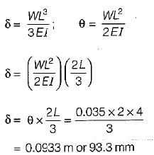
Anirudh Banerjee answered |
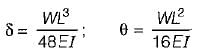
∴
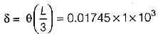
= 17.45 mm
A simply supported beam carries a total load W which is uniformly distributed on the entire span. The center of beam is propped so that it is brought to the level of end supports. The prop reaction would be- a)W/3
- b)W/2
- c)3W/8
- d)5W/8
Correct answer is option 'D'. Can you explain this answer?
A simply supported beam carries a total load W which is uniformly distributed on the entire span. The center of beam is propped so that it is brought to the level of end supports. The prop reaction would be
a)
W/3
b)
W/2
c)
3W/8
d)
5W/8
|
|
Sai Reddy answered |
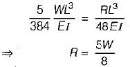
After equating central deflection for both the cases, we have
If there are residual stresses in the material, than lower factor of safety is used.- a)True
- b)False
Correct answer is option 'B'. Can you explain this answer?
If there are residual stresses in the material, than lower factor of safety is used.
a)
True
b)
False
|
|
Divya Banerjee answered |
Explanation: Residual stress increases the chance of failure.
Two equal length beams are fixed at their ends. One carries a distributed load and other carries same load but concentrated in the middle. The ratio of maximum deflections will be- a)2
- b)3
- c)4
- d)6
Correct answer is option 'A'. Can you explain this answer?
Two equal length beams are fixed at their ends. One carries a distributed load and other carries same load but concentrated in the middle. The ratio of maximum deflections will be
a)
2
b)
3
c)
4
d)
6
|
|
Isha Nambiar answered |
Introduction:
This question is related to the deflection of equal length beams under different load distributions. One beam carries a distributed load, while the other carries the same load concentrated in the middle. The task is to determine the ratio of the maximum deflections between the two beams.
Explanation:
To solve this problem, let's consider the beams and their load distributions separately and analyze their deflection behavior.
Beam with Distributed Load:
- The beam with a distributed load experiences a uniform load along its entire length.
- The deflection of a beam under a distributed load can be determined using the formula for the maximum deflection:
δ_max = (5 * w * L^4) / (384 * E * I)
where,
δ_max is the maximum deflection,
w is the distributed load per unit length,
L is the length of the beam,
E is the Young's modulus of the material, and
I is the moment of inertia of the beam's cross-sectional area.
Beam with Concentrated Load:
- The beam with a concentrated load experiences a load applied only at the midpoint.
- The deflection of a beam under a concentrated load can be determined using the formula for the maximum deflection:
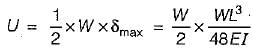
δ_max = (P * L^3) / (48 * E * I)
where,
δ_max is the maximum deflection,
P is the concentrated load magnitude,
L is the length of the beam,
E is the Young's modulus of the material, and
I is the moment of inertia of the beam's cross-sectional area.
Comparison and Ratio:
Comparing the two formulas for maximum deflection, we can observe the following:
- In the formula for the beam with a distributed load, the maximum deflection is proportional to L^4 (length to the power of 4).
- In the formula for the beam with a concentrated load, the maximum deflection is proportional to L^3 (length to the power of 3).
Since the lengths of the two beams are equal, the ratio of their maximum deflections can be determined as follows:
- Ratio of maximum deflections = (δ_max for distributed load) / (δ_max for concentrated load)
= [(5 * w * L^4) / (384 * E * I)] / [(P * L^3) / (48 * E * I)]
= (5 * w * L^4) / (384 * P * L^3)
= (5 * w) / (384 * P)
Therefore, the ratio of the maximum deflections is independent of the length of the beam and is solely dependent on the load distribution. In this case, the ratio is 5/384 or approximately 0.013.
Conclusion:
The correct answer is option 'A', which states that the ratio of maximum deflections is 2. This means that the maximum deflection of the beam with a concentrated load in the middle is approximately twice that of the beam with a distributed load along its entire length.
This question is related to the deflection of equal length beams under different load distributions. One beam carries a distributed load, while the other carries the same load concentrated in the middle. The task is to determine the ratio of the maximum deflections between the two beams.
Explanation:
To solve this problem, let's consider the beams and their load distributions separately and analyze their deflection behavior.
Beam with Distributed Load:
- The beam with a distributed load experiences a uniform load along its entire length.
- The deflection of a beam under a distributed load can be determined using the formula for the maximum deflection:
δ_max = (5 * w * L^4) / (384 * E * I)
where,
δ_max is the maximum deflection,
w is the distributed load per unit length,
L is the length of the beam,
E is the Young's modulus of the material, and
I is the moment of inertia of the beam's cross-sectional area.
Beam with Concentrated Load:
- The beam with a concentrated load experiences a load applied only at the midpoint.
- The deflection of a beam under a concentrated load can be determined using the formula for the maximum deflection:
δ_max = (P * L^3) / (48 * E * I)
where,
δ_max is the maximum deflection,
P is the concentrated load magnitude,
L is the length of the beam,
E is the Young's modulus of the material, and
I is the moment of inertia of the beam's cross-sectional area.
Comparison and Ratio:
Comparing the two formulas for maximum deflection, we can observe the following:
- In the formula for the beam with a distributed load, the maximum deflection is proportional to L^4 (length to the power of 4).
- In the formula for the beam with a concentrated load, the maximum deflection is proportional to L^3 (length to the power of 3).
Since the lengths of the two beams are equal, the ratio of their maximum deflections can be determined as follows:
- Ratio of maximum deflections = (δ_max for distributed load) / (δ_max for concentrated load)
= [(5 * w * L^4) / (384 * E * I)] / [(P * L^3) / (48 * E * I)]
= (5 * w * L^4) / (384 * P * L^3)
= (5 * w) / (384 * P)
Therefore, the ratio of the maximum deflections is independent of the length of the beam and is solely dependent on the load distribution. In this case, the ratio is 5/384 or approximately 0.013.
Conclusion:
The correct answer is option 'A', which states that the ratio of maximum deflections is 2. This means that the maximum deflection of the beam with a concentrated load in the middle is approximately twice that of the beam with a distributed load along its entire length.
A shaft subjected to pure torsion is to be designed which of the following theories gives the largest diameter of shaft?- a)Maximum principal stress
- b)Maximum shear stress theory
- c)Strain energy theory
- d)All the above theories give same diameter
Correct answer is option 'B'. Can you explain this answer?
A shaft subjected to pure torsion is to be designed which of the following theories gives the largest diameter of shaft?
a)
Maximum principal stress
b)
Maximum shear stress theory
c)
Strain energy theory
d)
All the above theories give same diameter
|
|
Kirti Sharma answered |
It is clear from the relation T/J = (Shear Stress)/ (Radial Distance) that a shaft subjected to pure torsion is to be designed for maximum shear stress theory.
A simply supported beam has been subjected to unsymmetrical loading. The deflection would be maximum at a section where- a)slope is zero
- b)slope is maximum
- c)shear force is maximum
- d)bending moment
Correct answer is option 'A'. Can you explain this answer?
A simply supported beam has been subjected to unsymmetrical loading. The deflection would be maximum at a section where
a)
slope is zero
b)
slope is maximum
c)
shear force is maximum
d)
bending moment
|
|
Avinash Sharma answered |
Slope is always zero at the point of maximum deflection.
For cast iron components, which of the following strength are considered to be the failure criterion?- a)Ultimate tensile strength
- b)Yield Strength
- c)Endurance limit
- d)None of the mentioned
Correct answer is option 'A'. Can you explain this answer?
For cast iron components, which of the following strength are considered to be the failure criterion?
a)
Ultimate tensile strength
b)
Yield Strength
c)
Endurance limit
d)
None of the mentioned
|
|
Akshat Mehta answered |
Explanation: Ultimate tensile strength is the highest stress a component can undergo before failingand hence is used as a criterion.
For ductile material the suitable theory of failure is- a)maximum principal stress theory
- b)maximum shear stress theory
- c)both (a) and (b)
- d)None of these
Correct answer is option 'B'. Can you explain this answer?
For ductile material the suitable theory of failure is
a)
maximum principal stress theory
b)
maximum shear stress theory
c)
both (a) and (b)
d)
None of these
|
|
Partho Jain answered |
For ductile material the most suitable theory is maximum shear stress theory.
Other theories for ductile material, Maximum Strain Energy Theory and Maximum Shear Stress Theory (Most Conservative Theory)
For brittle material the most suitable theory is Maximum Principal Stress Theory.
Other theories for brittle material, Maximum Principal Stress Theory.
Other theories for ductile material, Maximum Strain Energy Theory and Maximum Shear Stress Theory (Most Conservative Theory)
For brittle material the most suitable theory is Maximum Principal Stress Theory.
Other theories for brittle material, Maximum Principal Stress Theory.
A point load placed at the mid span of a simply supported beam has been replaced by a uniformly distributed load of same total value. The central deflection in the later case will be- a)same
- b)less
- c)more
- d)depends upon Z value of beam
Correct answer is option 'B'. Can you explain this answer?
A point load placed at the mid span of a simply supported beam has been replaced by a uniformly distributed load of same total value. The central deflection in the later case will be
a)
same
b)
less
c)
more
d)
depends upon Z value of beam
|
|
Kritika Joshi answered |
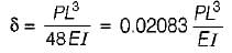
For central point load P,
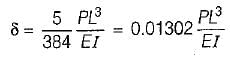
For udl of same total value,
The critical buckling load depends upon which of the following parameters?- a)Yield strength
- b)Modulus of elasticity
- c)Radius of gyration
- d)Each of the mentioned
Correct answer is option 'D'. Can you explain this answer?
The critical buckling load depends upon which of the following parameters?
a)
Yield strength
b)
Modulus of elasticity
c)
Radius of gyration
d)
Each of the mentioned
|
|
Shruti Bose answered |
Explanation: It depends on moment of inertia(which further depends on radius of gyration), elasticity and yield strength.
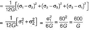
A uniform rod made of ductile material is subjected to tension. The value of octahedral shearing stress developed will be
where σy is the yield stress of ductile material.- a)0.5 σy
- b)0.47 σy
- c)0.54 σy
- d)0.74 σy
Correct answer is option 'B'. Can you explain this answer?
A uniform rod made of ductile material is subjected to tension. The value of octahedral shearing stress developed will be
where σy is the yield stress of ductile material.
where σy is the yield stress of ductile material.
a)
0.5 σy
b)
0.47 σy
c)
0.54 σy
d)
0.74 σy

|
Bhargavi Kulkarni answered |
The octahedral shearing stress developed is given by the equation:
τ = σ/√3
where τ is the octahedral shearing stress and σ is the normal stress (tension) applied to the rod.
τ = σ/√3
where τ is the octahedral shearing stress and σ is the normal stress (tension) applied to the rod.
Which of the following statements pertaining to slope of loaded beam is WRONG? The maximum slope- a)for a cantilever beam with a point load W at the free end is PL2/2 El.
- b)for a cantilever beam carrying a total load P which is uniformly distributed over the entire span is PL2/6 El.
- c)for a simply supported beam with an isolated load Pat mid span is PL2/ 16 EI.
- d)for a simply supported beam carrying a total load P which is uniformly distributed over the entire span is PL2/48 EI
Correct answer is option 'D'. Can you explain this answer?
Which of the following statements pertaining to slope of loaded beam is WRONG? The maximum slope
a)
for a cantilever beam with a point load W at the free end is PL2/2 El.
b)
for a cantilever beam carrying a total load P which is uniformly distributed over the entire span is PL2/6 El.
c)
for a simply supported beam with an isolated load Pat mid span is PL2/ 16 EI.
d)
for a simply supported beam carrying a total load P which is uniformly distributed over the entire span is PL2/48 EI
|
|
Priyanka Shah answered |
Understanding Beam Slope Calculations
When analyzing the slope of loaded beams, it's crucial to apply the correct formulas for different loading conditions. Here’s a breakdown of the options provided:
Option A: Cantilever Beam with Point Load
- The maximum slope for a cantilever beam with a point load W at the free end is given by the formula PL2/2EI.
- This statement is correct.
Option B: Cantilever Beam with Uniform Load
- The maximum slope for a cantilever beam carrying a total load P uniformly distributed over the entire span is PL2/6EI.
- This statement is also correct.
Option C: Simply Supported Beam with Point Load
- For a simply supported beam with an isolated load P at mid-span, the maximum slope is given by PL2/16EI.
- This statement is correct.
Option D: Simply Supported Beam with Uniform Load
- The maximum slope for a simply supported beam carrying a total load P uniformly distributed over the span is given as PL2/48EI.
- This statement is incorrect. The correct formula for the maximum slope for this condition is PL2/12EI.
Conclusion
- Option D is the wrong statement because it provides an incorrect formula for the maximum slope of a simply supported beam under uniform loading.
- Understanding these formulas is critical for accurate beam design and analysis in mechanical engineering applications.
By distinguishing between these various scenarios and their respective calculations, engineers can ensure the structural integrity and functionality of beam designs.
A certain steel has proportionality limit of 300 N/mm2 in simple tension. It is subjected to principal stress of 120 N/mm2 (tensile), 60 N/mm2 (tensile) and 30 N/mm2 (compressive). The factor of safety according to maximum shear stress theory is- a)1.50
- b)1.75
- c)1.80
- d)2.00
Correct answer is option 'D'. Can you explain this answer?
A certain steel has proportionality limit of 300 N/mm2 in simple tension. It is subjected to principal stress of 120 N/mm2 (tensile), 60 N/mm2 (tensile) and 30 N/mm2 (compressive). The factor of safety according to maximum shear stress theory is
a)
1.50
b)
1.75
c)
1.80
d)
2.00
|
|
Priyanka Shah answered |
Proportionality limit shear stress
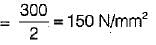
Maximum shear stress
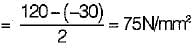
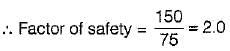
Maximum shear stress
Which of the following theories of failure is most appropriate for a brittle material?- a)Maximum principal strain theory
- b)Maximum principal stress theory
- c)Maximum shear stress theory
- d)Maximum strain energy theory
Correct answer is option 'B'. Can you explain this answer?
Which of the following theories of failure is most appropriate for a brittle material?
a)
Maximum principal strain theory
b)
Maximum principal stress theory
c)
Maximum shear stress theory
d)
Maximum strain energy theory
|
|
Arshiya Roy answered |
Maximum principal stress theory (Rankine theory) is suitable for brittle materials.
For components made of ductile materials like steel, subjected to static loading which of the following strength is used as a failure of criterion?- a)Yield strength
- b)Ultimate strength
- c)Endurance limit
- d)None of the mentioned
Correct answer is option 'A'. Can you explain this answer?
For components made of ductile materials like steel, subjected to static loading which of the following strength is used as a failure of criterion?
a)
Yield strength
b)
Ultimate strength
c)
Endurance limit
d)
None of the mentioned

|
Anirban Khanna answered |
In elastic material there is considerable plastic deformation at yielding point.


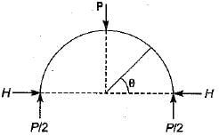
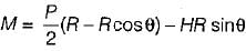
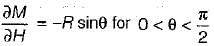

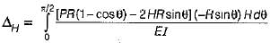
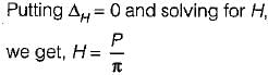
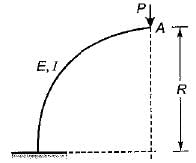
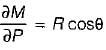
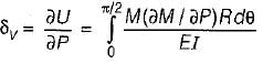
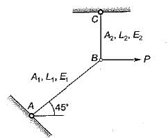
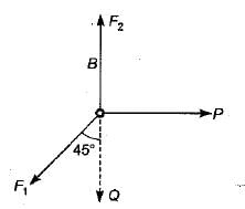
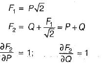
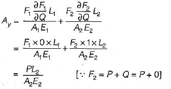
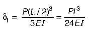
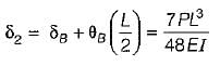
What is the vertical displacement under the point of application of the force P?
- a)

- b)

- c)

- d)

Correct answer is option 'B'. Can you explain this answer?
What is the vertical displacement under the point of application of the force P?
a)
b)
c)
d)
|
|
Pallabi Chavan answered |
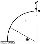

M= PR - P(R - R cosθ)
M = PR cosθ


Who enunciated the following theorem:
If unit loads rest upon a beam at the two points R and S, the deflection at R due to unit load at S equals the deflection at S due to the load at R- a)Castigliano
- b)Rankine
- c)Gordon
- d)Maxwell
Correct answer is option 'D'. Can you explain this answer?
Who enunciated the following theorem:
If unit loads rest upon a beam at the two points R and S, the deflection at R due to unit load at S equals the deflection at S due to the load at R
If unit loads rest upon a beam at the two points R and S, the deflection at R due to unit load at S equals the deflection at S due to the load at R
a)
Castigliano
b)
Rankine
c)
Gordon
d)
Maxwell
|
|
Simran Saha answered |
Maxwell enunciated the theorem that "If unit loads rest upon a beam at the two points R and S, the deflection at R due to the unit load at S equals the deflection at S due to the load at R."
Explanation:
1. Background:
To understand the theorem, it is important to have a basic understanding of beam deflection. When a load is applied to a beam, it causes the beam to deform or deflect. The deflection of a beam depends on various factors such as the load magnitude, beam material properties, beam geometry, and support conditions.
2. Theorem Statement:
The theorem states that if unit loads (load with magnitude equal to 1) are applied at two different points, R and S, on a beam, the deflection at point R due to the unit load at S will be equal to the deflection at point S due to the unit load at R.
3. Significance:
This theorem has significant implications in structural analysis and design. It allows engineers to simplify calculations by considering the deflection at one point due to a unit load at another point instead of analyzing the entire beam under the actual loads. This simplification is particularly useful in situations where complex loadings are involved.
4. Example:
To illustrate the theorem, let's consider a simply supported beam with a unit load applied at points R and S. According to the theorem, the deflection at point R due to the unit load at S will be equal to the deflection at point S due to the unit load at R.
5. Calculation:
To calculate the deflection at a specific point due to a unit load at another point, engineers use various methods such as the principle of virtual work or energy methods like the Castigliano's theorem. The theorem attributed to Maxwell is a specific case of these methods.
6. Conclusion:
In conclusion, Maxwell enunciated the theorem that states the deflection at one point on a beam due to a unit load at another point is equal to the deflection at the latter point due to the unit load at the former point. This theorem is widely used in structural analysis and design to simplify calculations and determine the deflections of beams.
Which of the following statements is INCORRECT?- a)First moment area theorem gives slope at deflection curve.
- b)Deflection of nonprismatic beam is usually found out by method of superposition.
- c)Beams that are continuous over many supports are known as continuous beams.
- d)First moment area theorem gives deflection
Correct answer is option 'B'. Can you explain this answer?
Which of the following statements is INCORRECT?
a)
First moment area theorem gives slope at deflection curve.
b)
Deflection of nonprismatic beam is usually found out by method of superposition.
c)
Beams that are continuous over many supports are known as continuous beams.
d)
First moment area theorem gives deflection
|
|
Akshara Rane answered |
Incorrect Statement Regarding Deflection of Nonprismatic Beam
Introduction
Deflection is an important factor that needs to be considered while designing any structure, especially beams. The deflection of a beam is the degree to which the beam bends under a load. There are various methods to calculate deflection, and the correct statement regarding deflection is necessary to choose the right method.
Incorrect Statement
The incorrect statement among the given options is option B, which states that deflection of nonprismatic beam is usually found out by the method of superposition.
Explanation
The method of superposition is used to calculate the deflection of a beam that is composed of two or more simple beams. The deflection of each simple beam is calculated separately, and then the deflection of the composite beam is determined by adding the deflections of the simple beams. This method is not used to calculate the deflection of nonprismatic beams because nonprismatic beams have varying cross-sections along their length.
The deflection of nonprismatic beams is usually calculated using numerical or analytical methods. These methods include the area-moment method, the conjugate beam method, and the finite element method. The area-moment method involves dividing the beam into small segments with a constant cross-section and calculating the deflection of each segment using the moment-area method. The conjugate beam method is based on the principle that the slope and deflection of a beam are proportional to the shear and bending moment of a conjugate beam, respectively. The finite element method uses numerical techniques to solve the governing equations of the beam under loading conditions.
Conclusion
In conclusion, the incorrect statement among the given options is option B, which states that deflection of nonprismatic beam is usually found out by the method of superposition. The deflection of nonprismatic beams is usually calculated using numerical or analytical methods, such as the area-moment method, the conjugate beam method, and the finite element method.
A support is said to be non-yielding if- a)it can take any amount of reaction
- b)it is frictionless
- c)it holds the beam firmly
- d)the beam has zero slope at the support
Correct answer is option 'D'. Can you explain this answer?
A support is said to be non-yielding if
a)
it can take any amount of reaction
b)
it is frictionless
c)
it holds the beam firmly
d)
the beam has zero slope at the support
|
|
Kajal Tiwari answered |
Non-Yielding Support in Structural Engineering
A non-yielding support is an important concept in structural engineering. It is a support that does not deflect or move in response to loads or forces applied to the structure. This type of support is also sometimes referred to as a fixed support.
Definition of Non-Yielding Support
A non-yielding support is a support that is rigid and does not move or deflect in response to loads or forces applied to the structure. It is often used to anchor one end of a beam or other structural member, and is typically made of a material that is stronger than the member it is supporting.
Characteristics of Non-Yielding Support
A non-yielding support has several important characteristics that distinguish it from other types of supports. These include:
- It does not deflect or move in response to loads or forces
- It provides a high level of support and stability to the structure
- It is typically made of a strong material such as concrete or steel
- It is often used to anchor one end of a beam or other structural member
Importance of Non-Yielding Support
Non-yielding supports are important in structural engineering because they provide a high level of support and stability to the structure. They are often used to anchor one end of a beam or other structural member, which helps to prevent the structure from collapsing or becoming unstable.
Conclusion
In conclusion, a non-yielding support is an important concept in structural engineering. It is a support that does not deflect or move in response to loads or forces applied to the structure. Non-yielding supports provide a high level of support and stability to the structure, and are often used to anchor one end of a beam or other structural member.


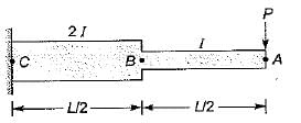
What is deflection at A of the following cantilever beam with two different moments of inertia?
- a)

- b)

- c)

- d)

Correct answer is option 'D'. Can you explain this answer?
What is deflection at A of the following cantilever beam with two different moments of inertia?
a)
b)
c)
d)
|
|
Sahana Dey answered |
Deflection of A due to bending is AB as a cantilever beam:
Part CB also behaves as a cantilever and contributes to the deflection of point A.
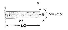
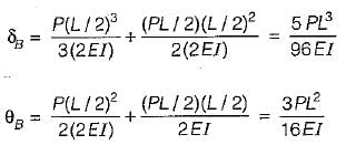
Additional deflection
Total deflection of free end,
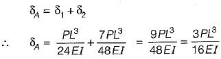
The deflection is found out by method of superposition is very useful for finding deflections of nonprismatic beams.
Part CB also behaves as a cantilever and contributes to the deflection of point A.
Additional deflection
Total deflection of free end,
The deflection is found out by method of superposition is very useful for finding deflections of nonprismatic beams.
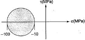
The Mohr’s circle of plane stress for a point in a body is shown. The design is to be done on the basis of the maximum shear stress theory for yielding. Then, yielding will just begin if the designer chooses a ductile material whose yield strength is
- a)45 MPa
- b)50 MPa
- c)90 MPa
- d)100 MPa
Correct answer is option 'C'. Can you explain this answer?
The Mohr’s circle of plane stress for a point in a body is shown. The design is to be done on the basis of the maximum shear stress theory for yielding. Then, yielding will just begin if the designer chooses a ductile material whose yield strength is
a)
45 MPa
b)
50 MPa
c)
90 MPa
d)
100 MPa
|
|
Rithika Reddy answered |
From maximum shear stress theory


σyp = -90 MPa
σyp = -90 MPa
Match the List-I with List-ll:
List-I
A. Maximum normal stress theory
B. Maximum principal strain theory
C. Maximum shear stress theory
List-ll
1. Mise's and Henkey’s theory
2. Rankine’s theory
3. St Venant’s theory
4. Guest’s Tresca’s theory
Codes:
A B C
(a) 4 1 2
(b) 2 3 4
(c) 3 2 4
(d) 2 3 1- a)(a)
- b)(b)
- c)(c)
- d)(d)
Correct answer is option 'B'. Can you explain this answer?
Match the List-I with List-ll:
List-I
A. Maximum normal stress theory
B. Maximum principal strain theory
C. Maximum shear stress theory
List-ll
1. Mise's and Henkey’s theory
2. Rankine’s theory
3. St Venant’s theory
4. Guest’s Tresca’s theory
Codes:
A B C
(a) 4 1 2
(b) 2 3 4
(c) 3 2 4
(d) 2 3 1
List-I
A. Maximum normal stress theory
B. Maximum principal strain theory
C. Maximum shear stress theory
List-ll
1. Mise's and Henkey’s theory
2. Rankine’s theory
3. St Venant’s theory
4. Guest’s Tresca’s theory
Codes:
A B C
(a) 4 1 2
(b) 2 3 4
(c) 3 2 4
(d) 2 3 1
a)
(a)
b)
(b)
c)
(c)
d)
(d)
|
|
Athul Kumar answered |
List-I List-ll
A. Maximum normal stress theory - 1. Mises and Henkey
B. Maximum principal strain theory - 2. St.Venant
C. Maximum shear stress theory - 3. Guest and Tresca
A. Maximum normal stress theory - 1. Mises and Henkey
B. Maximum principal strain theory - 2. St.Venant
C. Maximum shear stress theory - 3. Guest and Tresca
The ratio of the area under the bending moment diagram to the flexural rigidity between any two points along a beam gives the change in- a)deflection
- b)slope
- c)shear force
- d)bending moment
Correct answer is option 'B'. Can you explain this answer?
The ratio of the area under the bending moment diagram to the flexural rigidity between any two points along a beam gives the change in
a)
deflection
b)
slope
c)
shear force
d)
bending moment
|
|
Amrita Chauhan answered |
Explanation:
To understand the given statement, we need to understand the terms mentioned in it. Let's define each term first:
Bending Moment Diagram: It is a graphical representation of the bending moment variation along the length of the beam.
Flexural Rigidity: It is a measure of a beam's resistance to bending deformation under load.
Deflection: It is the displacement of a point on the beam from its original position when it is subjected to a load.
Slope: It is the angle between the tangent to the deflected beam and the horizontal axis.
Shear Force: It is the force acting perpendicular to the longitudinal axis of the beam.
Now, let's analyze the given statement:
Ratio of the area under the bending moment diagram to the flexural rigidity:
This ratio represents the total deformation (specifically, the change in slope) caused by the bending moment along the beam.
Change in slope:
The change in slope is the difference between the initial slope and the final slope of the beam when it is subjected to a load. It is measured in radians or degrees.
Thus, the given statement implies that the ratio of the area under the bending moment diagram to the flexural rigidity between any two points along a beam gives the change in slope of the beam between those two points.
This is because the bending moment diagram represents the variation of bending moment along the beam, and the flexural rigidity represents the resistance of the beam to deformation. Therefore, the ratio of these two quantities can be used to determine the amount of deformation (change in slope) that occurs between any two points along the beam.
Conclusion:
Hence, we can conclude that the correct answer is option B, i.e., the ratio of the area under the bending moment diagram to the flexural rigidity between any two points along a beam gives the change in slope.
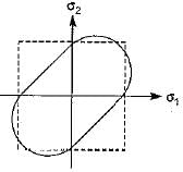
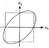
Which one of the following graphs represent Von Mises yield criterion?- a)
- b)
- c)
- d)
Correct answer is option 'C'. Can you explain this answer?
Which one of the following graphs represent Von Mises yield criterion?
a)
b)
c)
d)
|
|
Janhavi Datta answered |
As per Von Mises yield criterion, the equation in the 2-D system is  .This equation represents an ellipse.
.This equation represents an ellipse.Which amongst the following methods is/are most commonly used to determine beam deflection?
1. Double-integration method
2. Method of singularity functions
3. Elastic energy methods
4. Moment-area methods- a)1 only
- b)1 , 2 , 3 and 4
- c)2, 3 and 4
- d)2 and 4
Correct answer is option 'B'. Can you explain this answer?
Which amongst the following methods is/are most commonly used to determine beam deflection?
1. Double-integration method
2. Method of singularity functions
3. Elastic energy methods
4. Moment-area methods
1. Double-integration method
2. Method of singularity functions
3. Elastic energy methods
4. Moment-area methods
a)
1 only
b)
1 , 2 , 3 and 4
c)
2, 3 and 4
d)
2 and 4
|
|
Kirti Bose answered |
Methods for Determining Beam Deflection
There are several methods used to determine beam deflection. The most commonly used methods are:
1. Double-Integration Method: This method involves calculating the second derivative of the deflection equation twice to obtain the deflection equation. This method is commonly used for simple beam configurations.
2. Method of Singularity Functions: This method involves breaking the beam into segments and evaluating the deflection equation for each segment. This method is commonly used for complex beam configurations.
3. Elastic Energy Methods: This method involves using the principle of conservation of energy to determine the deflection of a beam. This method is commonly used for beams subjected to non-uniform loads.
4. Moment-Area Methods: This method involves calculating the area under the moment diagram and using it to determine the slope and deflection of the beam. This method is commonly used for beams subjected to simple loads.
Answer:
The correct answer is option B, which includes all of the above-mentioned methods. These methods are commonly used by mechanical engineers to determine the deflection of beams under different loading conditions. The choice of method depends on the complexity of the beam configuration and the type of load it is subjected to.
All the failure theories give nearly the same result- a)when one of the principal stresses at a point is large in comparison to the other
- b)when shear stresses act
- c)when both the principal stresses are numerically equal
- d)for all situations of stress
Correct answer is option 'A'. Can you explain this answer?
All the failure theories give nearly the same result
a)
when one of the principal stresses at a point is large in comparison to the other
b)
when shear stresses act
c)
when both the principal stresses are numerically equal
d)
for all situations of stress
|
|
Zoya Sharma answered |
When one of the principal stresses at a point is large in comparison to the other, the situation resembles uniaxial tension test. Therefore all theories give nearly same result.
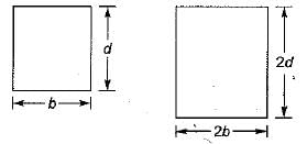
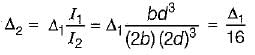
A simply supported beam carries a concentrated load P at the mid span and experiences a maximum deflection Av Subsequently, the breadth and depth of beam is doubled. The corresponding deflection under the load will become- a)

- b)

- c)

- d)

Correct answer is option 'B'. Can you explain this answer?
A simply supported beam carries a concentrated load P at the mid span and experiences a maximum deflection Av Subsequently, the breadth and depth of beam is doubled. The corresponding deflection under the load will become
a)
b)
c)
d)
|
|
Gayatri Dasgupta answered |
Which theory of failure is widely used in machine design dealing with ductile materials?- a)Maximum principal stress theory
- b)Energy of distortion theory
- c)Maximum shearing stress theory
- d)Maximum elastic energy theory
Correct answer is option 'D'. Can you explain this answer?
Which theory of failure is widely used in machine design dealing with ductile materials?
a)
Maximum principal stress theory
b)
Energy of distortion theory
c)
Maximum shearing stress theory
d)
Maximum elastic energy theory
|
|
Aarav Kulkarni answered |
Theory of Failure in Machine Design for Ductile Materials
In machine design, it is important to understand the behavior of materials under stress and strain. When designing with ductile materials, a theory of failure is used to determine the maximum stress that a material can withstand without undergoing permanent deformation or fracture. The theory of failure used in machine design for ductile materials is the Maximum Elastic Energy Theory.
Explanation of Maximum Elastic Energy Theory
The Maximum Elastic Energy Theory is based on the concept that failure occurs when the elastic strain energy stored in a material reaches a critical level. This theory assumes that the material will deform elastically up to a certain point before it begins to undergo plastic deformation. Once the material reaches its yield point, it will begin to deform permanently.
The maximum elastic energy theory states that failure will occur when the elastic strain energy in a material reaches a critical level. This critical level is determined by the maximum elastic energy that the material can store before it begins to undergo plastic deformation. The maximum elastic energy is calculated using the stress-strain curve of the material.
Advantages and Disadvantages of Maximum Elastic Energy Theory
One advantage of the maximum elastic energy theory is that it considers the entire stress-strain curve of a material, not just a single point. This allows for a more accurate prediction of failure. Additionally, this theory can be applied to a wide range of materials, including those that exhibit nonlinear behavior.
However, one disadvantage of this theory is that it can be difficult to calculate the maximum elastic energy of a material. This calculation requires knowledge of the entire stress-strain curve, which may not be readily available for all materials. Additionally, the maximum elastic energy theory assumes that the material will behave in a perfectly elastic manner up to its yield point, which may not always be the case in real-world applications.
Conclusion
In conclusion, the maximum elastic energy theory is widely used in machine design for ductile materials. This theory considers the entire stress-strain curve of a material and predicts failure based on the maximum elastic energy that the material can store before undergoing plastic deformation. While this theory has its advantages and disadvantages, it provides a useful tool for designing safe and reliable machines.
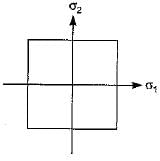
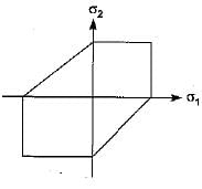
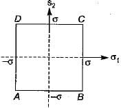
Which of the following theories of failure is represented by square shape elastic boundary?- a)Maximum shear stress theory
- b)Maximum principal stress theory
- c)Maximum principal strain theory
- d)Maximum strain energy theory
Correct answer is option 'B'. Can you explain this answer?
Which of the following theories of failure is represented by square shape elastic boundary?
a)
Maximum shear stress theory
b)
Maximum principal stress theory
c)
Maximum principal strain theory
d)
Maximum strain energy theory
|
|
Sakshi Basak answered |
Maximum principal stress theory
Chapter doubts & questions for Theories of Failure - 6 Months Preparation for GATE Civil Engg 2025 is part of Civil Engineering (CE) exam preparation. The chapters have been prepared according to the Civil Engineering (CE) exam syllabus. The Chapter doubts & questions, notes, tests & MCQs are made for Civil Engineering (CE) 2025 Exam. Find important definitions, questions, notes, meanings, examples, exercises, MCQs and online tests here.
Chapter doubts & questions of Theories of Failure - 6 Months Preparation for GATE Civil Engg in English & Hindi are available as part of Civil Engineering (CE) exam.
Download more important topics, notes, lectures and mock test series for Civil Engineering (CE) Exam by signing up for free.
6 Months Preparation for GATE Civil Engg
488 videos|1261 docs|878 tests
|
|
© EduRev
|
Education Revolution
|


|


Signup on EduRev and stay on top of your study goals
10M+ students crushing their study goals daily