


All Exams >
Civil Engineering (CE) >
6 Months Preparation for GATE Civil Engg >
All Questions
All questions of Connections for Civil Engineering (CE) Exam
For reversal of stresses the most suitable bolt is - a)Black bolt
- b)Turned bolt
- c)Friction grip bolt
- d)None of these
Correct answer is option 'C'. Can you explain this answer?
For reversal of stresses the most suitable bolt is
a)
Black bolt
b)
Turned bolt
c)
Friction grip bolt
d)
None of these

|
Sarthak Kulkarni answered |
Friction grip bolt is also called. High strength friction grip bolt or HSFG. The fatigue strength of these bolts is more because of no stress concentrations in the holes which makes it suitable to withstand reversal of stresses.

The maximum longitudinal pitch allowed in bolted joints of tension members is- a)16 times the diameter of the bolt
- b)32 times the diameter of the bolt
- c)16 times the thickness of the plate
- d)32 times the thickness of the plate
Correct answer is option 'C'. Can you explain this answer?
The maximum longitudinal pitch allowed in bolted joints of tension members is
a)
16 times the diameter of the bolt
b)
32 times the diameter of the bolt
c)
16 times the thickness of the plate
d)
32 times the thickness of the plate
|
|
Devansh Banerjee answered |
Maximum longitudinal pitch in bolted joints of tension members
The maximum longitudinal pitch allowed in bolted joints of tension members is an important consideration in the design of steel structures. It is defined as the distance between the centers of adjacent bolts along the direction of the applied load.
Formula
The maximum longitudinal pitch can be calculated using the following formula:
Maximum longitudinal pitch = 16 x t
Where t is the thickness of the plate.
Explanation
The maximum longitudinal pitch is limited to prevent the occurrence of excessive deformation, bending, or buckling of the connected plates. The value of 16 times the thickness of the plate is based on experimental and theoretical studies of bolted connections, and it has been found to provide a safe and reliable limit for most practical situations.
The maximum longitudinal pitch applies to tension members, which are members that are subjected to axial tension forces. These members include bolts, rods, cables, and other structural elements that carry tensile loads.
Conclusion
In conclusion, the maximum longitudinal pitch allowed in bolted joints of tension members is 16 times the thickness of the plate. This value should be used in the design of bolted connections to ensure the structural integrity and safety of steel structures.
What is the ratio of the yield stress in power driven shop rivets relative to the permissible bearing stress of mild steel?- a)1.0
- b)0.8
- c)0.6
- d)0.4
Correct answer is option 'B'. Can you explain this answer?
What is the ratio of the yield stress in power driven shop rivets relative to the permissible bearing stress of mild steel?
a)
1.0
b)
0.8
c)
0.6
d)
0.4
|
|
Anshul Kumar answered |
The yield stress in power drive rivets is 200MPa and bearing stress of mild steel is 250MPa.
Thus, ratio
= 200/250
=0.8
Thus, ratio
= 200/250
=0.8
A structural member carrying a pull of 700 kN is connected to a gusset plate using rivets of 20 mm diameter. If the pull required for shearing the rivets, to crush the rivets and to tear the plate per pitch length are 60 kN, 35 kN and 70 kN respectively, then the number of rivets required is
- a)12
- b)18
- c)20
- d)22
Correct answer is option 'C'. Can you explain this answer?
A structural member carrying a pull of 700 kN is connected to a gusset plate using rivets of 20 mm diameter. If the pull required for shearing the rivets, to crush the rivets and to tear the plate per pitch length are 60 kN, 35 kN and 70 kN respectively, then the number of rivets required is
a)
12
b)
18
c)
20
d)
22

|
Constructing Careers answered |
The number of rivers required = force/Rivit value.
Rivit value = min value of shearing, bearing and tearing.
So,
700/35= 20.
Rivit value = min value of shearing, bearing and tearing.
So,
700/35= 20.
The centre to centre maximum distance between bolts in tension member of thickness 10 mm is- a)200 mm
- b)160 mm
- c)120 mm
- d)100 mm
Correct answer is option 'B'. Can you explain this answer?
The centre to centre maximum distance between bolts in tension member of thickness 10 mm is
a)
200 mm
b)
160 mm
c)
120 mm
d)
100 mm
|
|
Maulik Das answered |
The distance between centres of two adjacent rivets, in a line lying in the direction of stress, shaff not exceed 16t or 200 mm, whichever is less in tension members and 12t or 200 mm, whichever is less in compression member
∴ c/c distance = Lesser of (16 x 10, 200)
= 160mm.
∴ c/c distance = Lesser of (16 x 10, 200)
= 160mm.
Minimum pitch of rivets in a riveted joint is- a)2.5 times the dia of rivet hole
- b)2.5 times the dia of rivet
- c)2.5 times the total thickness of the main plate
- d)2.0 times the thickness of thinner plate
Correct answer is option 'B'. Can you explain this answer?
Minimum pitch of rivets in a riveted joint is
a)
2.5 times the dia of rivet hole
b)
2.5 times the dia of rivet
c)
2.5 times the total thickness of the main plate
d)
2.0 times the thickness of thinner plate
|
|
Saptarshi Khanna answered |
Minimum pitch = 2.5 times the nomial dia of rivet.
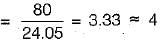
A 6 mm thick mild steel plate is connected to an 8 mm thick plate by 16 mm diameter shop rivets. What is-the number of rivets required to carry an 80 kN load?- a)2
- b)3
- c)4
- d)6
Correct answer is option 'C'. Can you explain this answer?
A 6 mm thick mild steel plate is connected to an 8 mm thick plate by 16 mm diameter shop rivets. What is-the number of rivets required to carry an 80 kN load?
a)
2
b)
3
c)
4
d)
6

|
Poulomi Khanna answered |
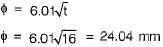
For shop rivets permissible stresses are, In shearing, τs = 100 MPa
In bearing, σb = 300 MPa
The gross diameter of hole (D)
.= 16 + 1.5 = 17.5 mm
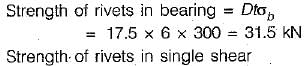
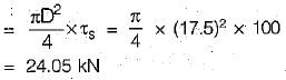
∴ Rivet value = 24.05 kN
Hence, number of rivets required
In bearing, σb = 300 MPa
The gross diameter of hole (D)
.= 16 + 1.5 = 17.5 mm
∴ Rivet value = 24.05 kN
Hence, number of rivets required
According to IS Specifications, the maximum pitch of rivets in compression is
(where t is thickness of thinnest outside plate or angle)
- a)lesser of 200 mm and 12 t
- b)lesser of 200 mm and 16 t
- c)lesser of 300 mm and 32 t
- d)lesser of 300 mm and 24 t
Correct answer is option 'A'. Can you explain this answer?
According to IS Specifications, the maximum pitch of rivets in compression is
(where t is thickness of thinnest outside plate or angle)
a)
lesser of 200 mm and 12 t
b)
lesser of 200 mm and 16 t
c)
lesser of 300 mm and 32 t
d)
lesser of 300 mm and 24 t
|
|
Hiral Sharma answered |
Maximum pitch of rivets in compression = 12t or 200 mm whichever is less
When load line coincides with the C.G. of rivet group, then the rivets are subjected to- a)Shear only
- b)Tension only
- c)Bending only
- d)Both shear and bending
Correct answer is option 'A'. Can you explain this answer?
When load line coincides with the C.G. of rivet group, then the rivets are subjected to
a)
Shear only
b)
Tension only
c)
Bending only
d)
Both shear and bending
|
|
Alok Iyer answered |
Explanation:
Load line coinciding with the C.G. of rivet group:
When the load line coincides with the center of gravity (C.G.) of the rivet group, it means that the load applied is passing through the center of gravity of the rivet group.
Rivets subjected to shear only:
- In this case, the load is directly acting on the C.G. of the rivet group, resulting in shear forces being applied to the rivets.
- Shear forces are forces that act parallel to the plane of the material, causing internal sliding or deformation of the material along the plane.
Therefore, when the load line coincides with the C.G. of the rivet group, the rivets are subjected to shear forces only. This is because the load is directly causing shear stresses within the rivet group, without inducing any tensile or bending stresses.
The difference between gross diameter and nominal diameter for the rivets up to 25 mm diameter is- a)1.0 mm
- b)1.5 mm
- c)2.0 mm
- d)2.5 mm
Correct answer is option 'B'. Can you explain this answer?
The difference between gross diameter and nominal diameter for the rivets up to 25 mm diameter is
a)
1.0 mm
b)
1.5 mm
c)
2.0 mm
d)
2.5 mm
|
|
Bhargavi Sengupta answered |
Gross diameter
= Nominal diameter + 1.5 mm, φ≤ 25 mm
Gross diameter
= Nominal diameter + 2 mm, φ > 25 mm φ = Nominal diameter
= Nominal diameter + 1.5 mm, φ≤ 25 mm
Gross diameter
= Nominal diameter + 2 mm, φ > 25 mm φ = Nominal diameter
When the axis of load lies in the plane of rivet group, then the most heavily loaded rivet will be the one which.where, Fa is the load shared by each rivet due to axial load and Fm is the shearing load due to moment in any rivet- a)is at the CG of the rivet group
- b)is at the minimum distance from CG of the rivet group
- c)gives the maximum angle between the two forces Fa and Fm
- d)gives the minimum angle between the two forces Fa and Fm
Correct answer is option 'D'. Can you explain this answer?
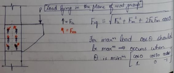
When the axis of load lies in the plane of rivet group, then the most heavily loaded rivet will be the one which.
where, Fa is the load shared by each rivet due to axial load and Fm is the shearing load due to moment in any rivet
a)
is at the CG of the rivet group
b)
is at the minimum distance from CG of the rivet group
c)
gives the maximum angle between the two forces Fa and Fm
d)
gives the minimum angle between the two forces Fa and Fm
|
|
Pallabi Kulkarni answered |
If the same number of rivets has been used in the joints then which of the following pattern will yield highest efficiency- a)Chain
- b)Staggered
- c)Diamond
- d)All of the above yield same efficiency
Correct answer is option 'C'. Can you explain this answer?
If the same number of rivets has been used in the joints then which of the following pattern will yield highest efficiency
a)
Chain
b)
Staggered
c)
Diamond
d)
All of the above yield same efficiency
|
|
Jaideep Malik answered |
The width of the main plate required is less in case diamond riveting. The critical section is diamond riveting passes through one or two rivet holes. The width of the plate required to accommodate diamond pattern is less than that for chain pattern by d(n - 1).
n = Number of rivets in chain riveting at critical section
d = Gross diameter of rivets
n = Number of rivets in chain riveting at critical section
d = Gross diameter of rivets
If the thickness of plate to be connected by a rivet is 16 mm, then suitable size of rivet as per Unwin’s formula will be- a)16 mm
- b)20 mm
- c)24 mm
- d)27 mm
Correct answer is option 'C'. Can you explain this answer?
If the thickness of plate to be connected by a rivet is 16 mm, then suitable size of rivet as per Unwin’s formula will be
a)
16 mm
b)
20 mm
c)
24 mm
d)
27 mm
|
|
Sankar Dasgupta answered |
According to Unwin’s formula nominal diameter of rivet is given by,
What is the permissible tensile stress in bolts used for column bases (fy is the yield stress of the steel)?- a)120N/mm2
- b)150N/mm2
- c)0.6fy
- d)0.4fy
Correct answer is option 'A'. Can you explain this answer?
What is the permissible tensile stress in bolts used for column bases (fy is the yield stress of the steel)?
a)
120N/mm2
b)
150N/mm2
c)
0.6fy
d)
0.4fy
|
|
Snehal Tiwari answered |
Permissible tensile stresses in bolts used for column bases is 120 N/mm2.
The type of stress induced in the foundation bolts fixing a column to its footing is- a)pure compression
- b)bearing
- c)pure tension
- d)bending
Correct answer is option 'C'. Can you explain this answer?
The type of stress induced in the foundation bolts fixing a column to its footing is
a)
pure compression
b)
bearing
c)
pure tension
d)
bending
|
|
Harsh Khanna answered |
The axial force from column needs to be transferred from column to footing and thus, mainly type of stress induced in the foundation bolts is pure tension.
Load on connection is not eccentric for- a)lap joint
- b)single cover butt joint
- c)double cover butt joint :
- d)all the joints mentioned in (a), (b) and (c) of the question
Correct answer is option 'C'. Can you explain this answer?
Load on connection is not eccentric for
a)
lap joint
b)
single cover butt joint
c)
double cover butt joint :
d)
all the joints mentioned in (a), (b) and (c) of the question

|
Anushka Yadav answered |
In the case of double cover butt joint, eccentricity of force does not exist and bending is eliminated whereas it exists in the case of lap joint.
The overlap of batten plates with the main members in welded connections should be more than (where t = thickness of batten plate)- a)2t
- b)4t
- c)6t
- d)8t
Correct answer is option 'B'. Can you explain this answer?
The overlap of batten plates with the main members in welded connections should be more than (where t = thickness of batten plate)
a)
2t
b)
4t
c)
6t
d)
8t
|
|
Aaditya Jain answered |
Overlap of Batten Plates in Welded Connections
Welded connections are commonly used in structural steelwork to join different members together. Batten plates are often used to provide additional support and reinforcement at the connection points. When designing welded connections with batten plates, it is important to ensure that the overlap between the batten plates and the main members is sufficient to ensure the strength and stability of the connection.
Reason for Overlap
The overlap of batten plates with the main members in welded connections is necessary to transfer the load effectively and prevent any failure or instability at the connection point. The batten plates help to distribute the load more evenly across the connection and prevent local stress concentrations. Therefore, the overlap should be designed to ensure that the load is transferred between the batten plates and the main members without any discontinuities or weak points.
Optimum Overlap Length
The optimum length of overlap between the batten plates and the main members depends on various factors, including the thickness of the batten plate (t). A general guideline is to have an overlap of at least 4 times the thickness of the batten plate (4t). This ensures that there is sufficient contact area between the batten plates and the main members to transfer the load effectively.
Reasoning for Option B
In the given options, the correct answer is option B, which states that the overlap of batten plates should be 4t. This is the recommended minimum overlap length based on industry standards and design guidelines. Having an overlap length of 4t provides sufficient contact area and ensures that the load is transferred effectively between the batten plates and the main members.
Conclusion
In welded connections with batten plates, the overlap between the batten plates and the main members is crucial for the strength and stability of the connection. The recommended minimum overlap length is 4 times the thickness of the batten plate. This ensures sufficient contact area and load transfer between the batten plates and the main members. Option B, stating that the overlap should be 4t, is the correct answer.
If the thickness of thinnest outside plate is 10 mm, then the maximum pitch of rivets in tension will be taken as- a)120 mm
- b)160 mm
- c)200 mm
- d)300 mm
Correct answer is option 'B'. Can you explain this answer?
If the thickness of thinnest outside plate is 10 mm, then the maximum pitch of rivets in tension will be taken as
a)
120 mm
b)
160 mm
c)
200 mm
d)
300 mm
|
|
Nidhi Patel answered |
Maximum pitch of rivets in tension = 16t or 200 mm whichever is less,
∴ Pitch = 16 x 10 = 160 mm
∴ Pitch = 16 x 10 = 160 mm
The common assumption that, ‘all rivets share equally a non-eccentric load’ is valid at a load- a)Below the working load
- b)Equal to the working load
- c)Above the working load
- d)Equal to the failure load
Correct answer is option 'D'. Can you explain this answer?
The common assumption that, ‘all rivets share equally a non-eccentric load’ is valid at a load
a)
Below the working load
b)
Equal to the working load
c)
Above the working load
d)
Equal to the failure load
|
|
Sahil Chawla answered |
Actually the outer rivets are subjected to greater shear as compared to the inner rivets. The assumption that all rivets share equally a non-eccentric load is approximately valid when the connection is subjected to static loads approaching ultimate strength.
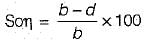
In a diamond riveting, for a plate of width 'b' and rivet diameter 'd', the efficiency of the joint is given by- a)(b - d)/b
- b)(b - 2d)/b
- c)(b - d)/d
- d)(b - 2d)/d
Correct answer is option 'A'. Can you explain this answer?
In a diamond riveting, for a plate of width 'b' and rivet diameter 'd', the efficiency of the joint is given by
a)
(b - d)/b
b)
(b - 2d)/b
c)
(b - d)/d
d)
(b - 2d)/d
|
|
Jay Sharma answered |
Efficiency of riveted joint,
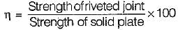
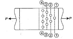
The section 1 - 1 is most critical. The strength of joint at section 1 - 1 is (b - d)tσat.
The strength of solid plate is b tσat
The section 1 - 1 is most critical. The strength of joint at section 1 - 1 is (b - d)tσat.
The strength of solid plate is b tσat
For a standard 45° fillet weld the ratio of size of fillet to throat thickness is- a)1 : 1
- b)√2 : 1
- c)1 : √2
- d)2 : 1
Correct answer is option 'C'. Can you explain this answer?
For a standard 45° fillet weld the ratio of size of fillet to throat thickness is
a)
1 : 1
b)
√2 : 1
c)
1 : √2
d)
2 : 1
|
|
Gauri Sarkar answered |
-minute therapy session, the therapist will typically charge between $100 and $250, depending on their experience, location, and specialty. However, some therapists may offer sliding scale fees based on income or offer discounts for multiple sessions or packages. It is important to discuss fees and payment options with your therapist before starting therapy. Additionally, some insurance plans may cover therapy sessions, so it is important to check with your insurance provider about coverage and any limitations or requirements for reimbursement.
A bolt designated as Hex bolt M 16 x 70 NL will have- a)Diameter of 16 mm
- b)Diameter of 70 mm
- c)Length of 16 mm
- d)Cross-sectional area of 16 x 70 cm2
Correct answer is option 'A'. Can you explain this answer?
A bolt designated as Hex bolt M 16 x 70 NL will have
a)
Diameter of 16 mm
b)
Diameter of 70 mm
c)
Length of 16 mm
d)
Cross-sectional area of 16 x 70 cm2
|
|
Arya Menon answered |
Hex bolt M 16 x 70 NL
Hex bolt M 16 x 70 NL is a type of bolt used in various construction and engineering applications. It is important to understand the specifications of this bolt in order to use it effectively. The specifications of this bolt can be broken down into the following:
1. Hex Bolt
Hex bolt refers to the shape of the head of the bolt. It has six sides, which makes it easier to grip and tighten with a wrench or socket.
2. M 16
M 16 refers to the diameter of the bolt. In this case, the diameter is 16 mm.
3. 70
70 refers to the length of the bolt. In this case, the length is 70 mm.
4. NL
NL refers to the thread type of the bolt. In this case, it stands for "non-locking", which means the bolt does not have any locking features.
Therefore, the correct answer is option A, which states that the bolt has a diameter of 16 mm.
For rivets in tension with countersunk heads, the tensile value shall be- a)Reduced by 25%
- b)Reduced by 33.3%
- c)Increased by 25%
- d)Increased by 33.3%
Correct answer is option 'B'. Can you explain this answer?
For rivets in tension with countersunk heads, the tensile value shall be
a)
Reduced by 25%
b)
Reduced by 33.3%
c)
Increased by 25%
d)
Increased by 33.3%
|
|
Simran Saha answered |
Rivets in Tension with Countersunk Heads
When it comes to rivets in tension with countersunk heads, there are a few things to consider. One of these is the tensile value of the rivets. This is important because it determines how much force the rivets can withstand before they fail.
Effect on Tensile Value
The question asks what happens to the tensile value of rivets in tension with countersunk heads. The correct answer is that the tensile value is reduced by 33.3%. This means that the rivets are not able to withstand as much force as they would if they did not have countersunk heads.
Reason for Reduction
There are a few reasons why the tensile value is reduced for rivets in tension with countersunk heads:
• The countersunk head creates a stress concentration, which can weaken the rivet.
• The countersink also reduces the cross-sectional area of the rivet, which reduces its strength.
• The countersink can also create a notch in the rivet, which can act as a stress concentrator and weaken the rivet further.
Conclusion
In conclusion, rivets in tension with countersunk heads have a reduced tensile value. This means that they are not as strong as rivets without countersunk heads and cannot withstand as much force before they fail. When using these types of rivets, it is important to take this reduction in strength into account and ensure that the design is appropriate for the anticipated loads.
Which one of the following is the mode of failure in a fillet weld material?- a)Tension
- b)Shear
- c)Bearing
- d)Crushing
Correct answer is option 'B'. Can you explain this answer?
Which one of the following is the mode of failure in a fillet weld material?
a)
Tension
b)
Shear
c)
Bearing
d)
Crushing
|
|
Prasad Desai answered |
The mode of failure in a fillet weld material is shear.
Shear failure occurs when the applied load is parallel to the area of the material. In the case of fillet welds, the load is typically applied parallel to the weld, causing shear stress to develop in the weld material.
Here is a detailed explanation of why shear is the mode of failure in fillet welds:
1. Understanding Fillet Welds:
- Fillet welds are commonly used in structural steel connections to join two pieces of metal at an angle.
- They are often used to provide strength and stability in various applications, such as in the construction of buildings, bridges, and other steel structures.
- Fillet welds are typically triangular in shape and are formed by depositing molten filler metal between the two pieces of metal to be joined.
2. Load Transfer in Fillet Welds:
- In fillet welds, the load is transferred from one member to another through the weld.
- When an external force is applied to the joint, the load is distributed across the fillet weld.
- The load is transferred primarily through shear stress, as the applied load is parallel to the weld.
3. Shear Failure in Fillet Welds:
- Shear failure occurs when the shear stress exceeds the shear strength of the weld material.
- The shear strength of a fillet weld depends on various factors, such as the material properties of the weld metal and the base metal, the size of the weld, and the welding process used.
- If the applied load exceeds the shear strength of the fillet weld, shear failure will occur, resulting in the separation or tearing of the weld material.
4. Other Modes of Failure:
- While shear is the primary mode of failure in fillet welds, other failure modes can also occur depending on the specific conditions.
- Tension failure can occur if the applied load causes the base metal adjacent to the weld to elongate and eventually rupture.
- Bearing failure can occur if the load causes the base metal to deform or crush, resulting in a loss of contact between the two pieces being joined.
- Crushing failure can occur if the weld material or the base metal is subjected to excessive compressive forces, causing it to deform or collapse.
In conclusion, the mode of failure in a fillet weld material is shear. Shear failure occurs when the applied load is parallel to the weld, causing the weld material to separate or tear. While other failure modes can also occur in certain circumstances, shear is the primary mode of failure in fillet welds.
By providing sufficient edge distance, which of the following failures of riveted joint can be avoided?- a)Tension failure of the plate
- b)Shear failure of the rivet
- c)Shear failure of the plate
- d)Crushing failure of the rivet
Correct answer is option 'C'. Can you explain this answer?
By providing sufficient edge distance, which of the following failures of riveted joint can be avoided?
a)
Tension failure of the plate
b)
Shear failure of the rivet
c)
Shear failure of the plate
d)
Crushing failure of the rivet
|
|
Jyoti Choudhury answered |
Avoiding Shear Failure of the Plate by Providing Sufficient Edge Distance
Sufficient edge distance is essential in avoiding shear failure of the plate in a riveted joint. The following are the reasons why:
- Shear failure of the plate occurs when the plate is unable to resist the shear force acting on it. This can happen when the rivet is located too close to the edge of the plate.
- Sufficient edge distance refers to the distance between the edge of the plate and the centerline of the rivet hole. This distance should be large enough to prevent shear failure of the plate.
- The required edge distance depends on the thickness of the plate and the diameter of the rivet. Generally, a minimum edge distance of 1.5 times the rivet diameter is recommended.
- When the edge distance is insufficient, the shear force acting on the plate will cause it to deform and eventually fail. This can result in the failure of the entire joint.
- By providing sufficient edge distance, the plate is able to resist the shear force without deforming or failing. This ensures the stability and safety of the joint.
In conclusion, providing sufficient edge distance is crucial in preventing shear failure of the plate in a riveted joint. Civil engineers must take into consideration the thickness of the plate and the diameter of the rivet when determining the required edge distance.
When the effect of wind or earthquake load is considered in the design of rivets and bolts for steel structures, by what percentage the permissible stresses may be exceeded?- a)15%
- b)25%
- c)33.33%
- d)50%
Correct answer is option 'B'. Can you explain this answer?
When the effect of wind or earthquake load is considered in the design of rivets and bolts for steel structures, by what percentage the permissible stresses may be exceeded?
a)
15%
b)
25%
c)
33.33%
d)
50%
|
|
Pallabi Tiwari answered |
In the design of rivets and bolts for steel structures, the effect of wind or earthquake load is taken into consideration to ensure the safety and stability of the structure. These loads can create additional stresses on the connections, and therefore it is important to account for them in the design process.
When considering wind or earthquake load, it is common practice to increase the permissible stresses in rivets and bolts. This is done to provide a safety margin and to account for the uncertainties and variability in the actual loads experienced by the structure. The percentage by which the permissible stresses may be exceeded is typically specified in design codes and standards.
The correct answer to the question is option 'B', which states that the permissible stresses may be exceeded by 25%. This means that the design calculations should be based on a stress level that is 25% higher than the allowable stress for the material. This additional allowance ensures that the connections can withstand the increased loads and provides a factor of safety.
By exceeding the permissible stresses by 25%, the design accounts for the uncertainties and variability in the actual loads. It also ensures that the connections have sufficient strength to resist the wind or earthquake forces without experiencing failure or excessive deformation.
It is worth noting that the specific percentage by which the permissible stresses may be exceeded can vary depending on the design code or standard being used. Different codes may have different requirements and factors of safety. Therefore, it is important to refer to the applicable design code or standard to determine the exact percentage to be used in the design calculations.
In conclusion, when considering the effect of wind or earthquake load in the design of rivets and bolts for steel structures, the permissible stresses may be exceeded by 25%. This provides a safety margin and accounts for the uncertainties and variability in the actual loads experienced by the structure.
The effective length of a fillet weld of length L and size s is given by- a)L - √2 S
- b)L - 2s
- c)

- d)L
Correct answer is option 'B'. Can you explain this answer?
The effective length of a fillet weld of length L and size s is given by
a)
L - √2 S
b)
L - 2s
c)
d)
L
|
|
Sahana Dey answered |
The effective length of a fillet weld is equal to its overall length minus twice the weld size. The effective length of a fillet weld designed to transmit loading should not be. less than four times weld size.
Which of the following does not describe a weld type?- a)Butt
- b)Plug
- c)Zig-Zag
- d)Lap
Correct answer is option 'C'. Can you explain this answer?
Which of the following does not describe a weld type?
a)
Butt
b)
Plug
c)
Zig-Zag
d)
Lap
|
|
Subham Unni answered |
Weld Types in Civil Engineering
Welding is a process of joining two pieces of metal by melting the edges and bringing them together. There are various types of welds used in civil engineering. Some of them are:
1. Butt Weld
A butt weld is a joint made by joining two metal pieces along their edges. This type of weld is commonly used in pipes and other structural applications.
2. Plug Weld
A plug weld is a type of weld where a hole is drilled in one of the metal pieces, and the other piece is welded to it. This type of weld is commonly used in sheet metal applications.
3. Lap Weld
A lap weld is a type of weld where the edges of two metal pieces overlap each other, and the weld is made along the overlapping edges. This type of weld is commonly used in sheet metal and structural applications.
4. Zig-Zag Weld
A zig-zag weld is a type of weld where the welding is done in a zig-zag pattern. This type of weld is commonly used in sheet metal applications.
The answer to the given question is option 'C', which is Zig-Zag. Zig-Zag is not a type of weld used in civil engineering.
Which of the following methods of design would be suitable for metal structures subjected to stress reversals and impact?
1. Simple working stress design
2. Rigid plastic design
3. Semirigid design
4. Elastic rigid designSelect the correct answer using the codes given below:- a)1, 2 and 4
- b)1, 3 and 4
- c)1, 2 and 3
- d)2, 3 and 4
Correct answer is option 'B'. Can you explain this answer?
Which of the following methods of design would be suitable for metal structures subjected to stress reversals and impact?
1. Simple working stress design
2. Rigid plastic design
3. Semirigid design
4. Elastic rigid design
1. Simple working stress design
2. Rigid plastic design
3. Semirigid design
4. Elastic rigid design
Select the correct answer using the codes given below:
a)
1, 2 and 4
b)
1, 3 and 4
c)
1, 2 and 3
d)
2, 3 and 4
|
|
Sankar Dasgupta answered |
Simple Working Stress Design
- Simple working stress design may not be suitable for metal structures subjected to stress reversals and impact as it does not take into account the cyclic loading and impact factors that can lead to fatigue failure.
Semirigid Design
- Semirigid design considers the flexibility of the structure and allows for some movement under stress reversals and impact, making it more suitable for such conditions compared to simple working stress design.
Elastic Rigid Design
- Elastic rigid design takes into account the elastic behavior of the structure under stress reversals and impact, providing a more accurate representation of the structural response compared to simple working stress design.
Therefore, options 1, 3, and 4 (Simple working stress design, Semirigid design, and Elastic rigid design) would be more suitable for metal structures subjected to stress reversals and impact.
What is the maximum permissible longitudinal pitch in staggered riveted compression joints?- a)500 mm
- b)400 mm
- c)300 mm
- d)100 mm
Correct answer is option 'C'. Can you explain this answer?
What is the maximum permissible longitudinal pitch in staggered riveted compression joints?
a)
500 mm
b)
400 mm
c)
300 mm
d)
100 mm
|
|
Harsh Khanna answered |
Longitudinal Pitch in Staggered Riveted Compression Joints
In a staggered riveted compression joint, the longitudinal pitch is the distance between two consecutive rows of rivets along the direction of the main stress. This pitch is crucial in ensuring the joint's stability and strength. The maximum permissible longitudinal pitch is determined by the joint's design and the material properties.
Permissible Maximum Longitudinal Pitch
The maximum permissible longitudinal pitch in staggered riveted compression joints is 300 mm. This value is based on the following considerations:
1. Joint Strength: A larger longitudinal pitch increases the joint's stress concentration and reduces its strength. Therefore, a smaller pitch is preferred.
2. Stability: A smaller longitudinal pitch provides better stability to the joint and prevents buckling.
3. Rivet Spacing: The longitudinal pitch should be smaller than the rivet spacing to maintain the joint's integrity.
4. Material Properties: The maximum permissible longitudinal pitch is influenced by the material's ductility and strength.
Conclusion
The maximum permissible longitudinal pitch in staggered riveted compression joints is 300 mm. This value ensures the joint's strength, stability, and integrity. A smaller pitch is preferred to reduce stress concentration and prevent buckling. The pitch should be smaller than the rivet spacing and should consider the material properties.
Which of the following is in violation of assumptions made in riveted joint analysis- a)Deformation of plates is neglected
- b)Rivets are rigid
- c)Stress concentration is neglected
- d)None of these
Correct answer is option 'A'. Can you explain this answer?
Which of the following is in violation of assumptions made in riveted joint analysis
a)
Deformation of plates is neglected
b)
Rivets are rigid
c)
Stress concentration is neglected
d)
None of these

|
Rutuja Pillai answered |
Deformation of plates is neglected:
Ignoring the deformation of plates in a riveted joint analysis is a violation of one of the assumptions made in the analysis. Let's break down why this assumption is important and how it affects the overall analysis:
- Importance of plate deformation:
- Neglecting the deformation of plates can lead to inaccurate results in the analysis of a riveted joint. When a load is applied to the joint, the plates will deform due to the applied forces. This deformation can affect the stress distribution within the joint and ultimately influence its strength and stability.
- Effects on stress distribution:
- When plates deform under load, the stress distribution in the joint will not be uniform. Ignoring plate deformation can result in underestimating the stresses in certain regions of the joint, leading to a potential failure of the joint.
- Impact on joint behavior:
- The behavior of a riveted joint is significantly influenced by the deformation of plates. If this deformation is not taken into account, the analysis may not accurately predict the joint's response to external loads. This can have serious implications for the structural integrity and safety of the joint.
In conclusion, neglecting the deformation of plates is a critical violation of assumptions in riveted joint analysis. It is essential to consider plate deformation in order to ensure accurate and reliable results in the analysis of such joints.
Consider the following statements:
Aluminum is being increasingly used for structural purposes because
1. Its modulus of elasticity is double that of steel
2. Its coefficient of thermal expansion is half that of steel
3. It requires less maintenance
4. The strength to unit weight ratio of aluminum is highWhich of these statements are correct?- a)1 and 4
- b)2 and 4
- c)1, 2 and 3
- d)3 and 4
Correct answer is option 'D'. Can you explain this answer?
Consider the following statements:
Aluminum is being increasingly used for structural purposes because
1. Its modulus of elasticity is double that of steel
2. Its coefficient of thermal expansion is half that of steel
3. It requires less maintenance
4. The strength to unit weight ratio of aluminum is high
Aluminum is being increasingly used for structural purposes because
1. Its modulus of elasticity is double that of steel
2. Its coefficient of thermal expansion is half that of steel
3. It requires less maintenance
4. The strength to unit weight ratio of aluminum is high
Which of these statements are correct?
a)
1 and 4
b)
2 and 4
c)
1, 2 and 3
d)
3 and 4
|
|
Varun Mukherjee answered |
Modulus of Elasticity and Strength to Weight Ratio
- Statement 1 is correct as aluminum indeed has a modulus of elasticity that is approximately double that of steel. This property makes aluminum a suitable material for structural purposes as it can withstand higher loads without deforming.
- Statement 4 is also correct as aluminum has a high strength to unit weight ratio. This means that it is lightweight but still possesses high strength, making it an excellent choice for structural applications where weight is a concern.
Coefficient of Thermal Expansion and Maintenance
- Statement 2 is not correct as the coefficient of thermal expansion of aluminum is actually higher than that of steel, not half as mentioned. This property can sometimes lead to issues in structures where temperature variations are significant.
- Statement 3 is also not entirely accurate. While aluminum does require less maintenance in terms of corrosion resistance compared to steel, it may still require maintenance due to other factors such as surface finish, potential for fatigue failure, etc.
Conclusion
- Therefore, the correct statements are 1 and 4, highlighting the superior modulus of elasticity and strength to weight ratio of aluminum compared to steel. This makes aluminum an increasingly popular choice for structural purposes in various industries.
When two plates are placed end to end and are joined by two cover plates the joint is known is- a)Lap joint
- b)Butt joint
- c)Chain riveted lap joint
- d)Double cover butt joint
Correct answer is option 'D'. Can you explain this answer?
When two plates are placed end to end and are joined by two cover plates the joint is known is
a)
Lap joint
b)
Butt joint
c)
Chain riveted lap joint
d)
Double cover butt joint
|
|
Harshad Iyer answered |
Introduction:
In civil engineering, when two plates are placed end to end and joined by two cover plates, the joint is known as a double cover butt joint. This type of joint is commonly used in various applications such as bridges, buildings, and other structures.
Explanation:
The double cover butt joint is a specific type of joint used to connect two plates end to end. It involves the use of two cover plates on either side of the joint to provide additional strength and support. This joint configuration offers several advantages in terms of load-carrying capacity and structural integrity.
Key Features:
The key features of a double cover butt joint include:
1. End-to-end connection: The plates are placed in a manner that their ends are aligned, ensuring a continuous connection between the two plates.
2. Cover plates: Two cover plates are used to join the two plates. These cover plates are placed on either side of the joint and extend beyond the edges of the two plates. They are typically welded or bolted to the plates to create a strong connection.
3. Increased strength: The use of cover plates enhances the strength of the joint by distributing the load over a larger area. This helps in minimizing stress concentrations and increases the load-carrying capacity of the joint.
4. Improved stiffness: The double cover butt joint offers improved stiffness compared to other joint types, as the cover plates contribute to the overall rigidity of the joint. This helps in reducing deflections and deformations under applied loads.
Advantages:
The double cover butt joint offers several advantages, including:
1. Increased load-carrying capacity: The use of cover plates enhances the load-carrying capacity of the joint, making it suitable for applications where high strength is required.
2. Improved structural integrity: The joint provides improved structural integrity by minimizing stress concentrations and distributing loads more evenly.
3. Enhanced stiffness: The double cover butt joint offers improved stiffness, reducing deflections and deformations under applied loads.
4. Easy fabrication: The joint is relatively easy to fabricate, making it cost-effective and time-efficient.
Applications:
The double cover butt joint is commonly used in various civil engineering applications, including:
1. Bridges: It is used to join steel or concrete girders in bridge construction, allowing for a continuous load path across the girders.
2. Buildings: The joint is used in the construction of steel structures, such as columns and beams, to provide a strong and rigid connection.
3. Industrial structures: It finds application in the construction of industrial structures, such as warehouses and factories, where high load-carrying capacity is required.
4. Infrastructure projects: The joint is also used in infrastructure projects like tunnels, flyovers, and marine structures to ensure structural stability and integrity.
Conclusion:
The double cover butt joint is a commonly used joint in civil engineering, offering increased load-carrying capacity, improved structural integrity, and enhanced stiffness. It finds application in various construction projects, providing a strong and reliable connection between two plates.
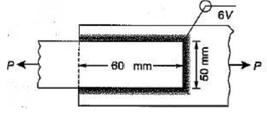
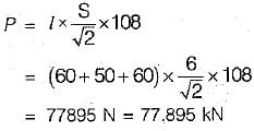
What is the safe load P that can be transmitted by the fillet-welded joint shown in the figure below if the safe allowable shear stress in the fillet weld is 108 MPa?
- a)60 kN
- b)66 kN
- c)77 kN
- d)81 kN
Correct answer is option 'C'. Can you explain this answer?
What is the safe load P that can be transmitted by the fillet-welded joint shown in the figure below if the safe allowable shear stress in the fillet weld is 108 MPa?
a)
60 kN
b)
66 kN
c)
77 kN
d)
81 kN
|
|
Jaideep Malik answered |
The safe load that can be transmitted by the fillet welded joint is given by,
Match List-I (Failure mode) with List-II (Reason) and select the correct answer using the codes given below the lists:
List-I
A. Shear failure of plates
B. Bearing failure of plates
C. Tearing failure of plates
D. Splitting failure of plates
List-II
1. Insufficient edge distance
2. Strength of plate is less than that of the rivets
- a)c
- b)b
- c)a
- d)d
Correct answer is option 'C'. Can you explain this answer?
Match List-I (Failure mode) with List-II (Reason) and select the correct answer using the codes given below the lists:
List-I
A. Shear failure of plates
B. Bearing failure of plates
C. Tearing failure of plates
D. Splitting failure of plates
List-II
1. Insufficient edge distance
2. Strength of plate is less than that of the rivets
List-I
A. Shear failure of plates
B. Bearing failure of plates
C. Tearing failure of plates
D. Splitting failure of plates
List-II
1. Insufficient edge distance
2. Strength of plate is less than that of the rivets
a)
c
b)
b
c)
a
d)
d
|
|
Pranavi Choudhury answered |
The tension and tearing of plates can be avoided by providing enough edge distance and minimum pitch distance
Which one of the following is correct?
The permissible stresses in a weld are usually taken as- a)less than those of the parent body
- b)equal to those of the parent body
- c)more than those of the parent body
- d)any desired value
Correct answer is option 'B'. Can you explain this answer?
Which one of the following is correct?
The permissible stresses in a weld are usually taken as
The permissible stresses in a weld are usually taken as
a)
less than those of the parent body
b)
equal to those of the parent body
c)
more than those of the parent body
d)
any desired value
|
|
Siddharth Datta answered |
Explanation:
Permissible Stresses in a Weld:
- When two metal parts are joined together by welding, a new area of metal is formed at the joint.
- This area is called the weld, and it has different properties than the parent metal.
- The permissible stress for a weld is the maximum stress that the weld can withstand without breaking or failing.
- The permissible stress is determined by the strength and quality of the weld and the type of loading that the weld will be subjected to.
Comparison with Parent Body:
- The permissible stresses in a weld are usually taken as equal to those of the parent body.
- This means that the weld is designed to have the same strength as the parent metal.
- However, in some cases, the permissible stresses in a weld may be less than those of the parent body.
- This is because the weld may have defects or imperfections that reduce its strength.
Importance of Permissible Stresses:
- It is important to take into account the permissible stresses in a weld when designing a structure or component.
- If the weld is not strong enough, it can fail and cause the structure to collapse or the component to malfunction.
- On the other hand, if the weld is stronger than necessary, it can add unnecessary weight and cost to the structure or component.
Conclusion:
- In summary, the permissible stresses in a weld are usually taken as equal to those of the parent body.
- This ensures that the weld is designed to have the same strength as the parent metal.
- However, in some cases, the permissible stresses in a weld may be less than those of the parent body, depending on the quality and strength of the weld.

Chapter doubts & questions for Connections - 6 Months Preparation for GATE Civil Engg 2025 is part of Civil Engineering (CE) exam preparation. The chapters have been prepared according to the Civil Engineering (CE) exam syllabus. The Chapter doubts & questions, notes, tests & MCQs are made for Civil Engineering (CE) 2025 Exam. Find important definitions, questions, notes, meanings, examples, exercises, MCQs and online tests here.
Chapter doubts & questions of Connections - 6 Months Preparation for GATE Civil Engg in English & Hindi are available as part of Civil Engineering (CE) exam.
Download more important topics, notes, lectures and mock test series for Civil Engineering (CE) Exam by signing up for free.
6 Months Preparation for GATE Civil Engg
488 videos|1261 docs|878 tests
|
|
© EduRev
|
Education Revolution
|


|


Signup on EduRev and stay on top of your study goals
10M+ students crushing their study goals daily