


All Exams >
Civil Engineering (CE) >
6 Months Preparation for GATE Civil Engg >
All Questions
All questions of Plastic Analysis for Civil Engineering (CE) Exam
For an I-beam, shape factor is 1.12. The factor of safety in bending is 1.5. if the allowable stress is increased by 20% for wind and earthquake loads, then the load factor is - a)1.10
- b)1.25
- c)1.35
- d)1.40
Correct answer is option 'D'. Can you explain this answer?
For an I-beam, shape factor is 1.12. The factor of safety in bending is 1.5. if the allowable stress is increased by 20% for wind and earthquake loads, then the load factor is
a)
1.10
b)
1.25
c)
1.35
d)
1.40
|
|
Sanvi Kapoor answered |
With increase in allowable stress, the factor of safety will reduce to 1.5/1.2 = 1.25.
∴ Load Factor = FS x shape factor
= 1.25 x 1.12
= 1.40

The plastic hinge formed in a collapse mechanism are 4 and the indeterminacy is 3. The collapse is- a)Partial
- b)Complete
- c)Over complete
- d)Under complete
Correct answer is option 'B'. Can you explain this answer?
The plastic hinge formed in a collapse mechanism are 4 and the indeterminacy is 3. The collapse is
a)
Partial
b)
Complete
c)
Over complete
d)
Under complete

|
Navya Kaur answered |
If the number of plastic hinges in the collapse mechanism are less than (r + 1) the collapse is called partial collapse. In such a case, part of the structure may fail making it useless as a whole. If the number of plastic hinges in the collapse mechanism are (r + 1) the collapse is called complete collapse. Such a mechanism has only one degree of freedom. If the number of plastic hinges developed are more than (r + 1), the collapse is called over complete collapse. In such a case there are two or more mechanisms for which the corresponding value of the load is the same, this load value being the actual coljapse load.
If the degree of indeterminacy is r, and the number of plastic hinges developed is N then,
N < (r + 1) Partial collapse
N = r + 1 Complete collapse .
N > r + 1 Overcomplete collapse
If the degree of indeterminacy is r, and the number of plastic hinges developed is N then,
N < (r + 1) Partial collapse
N = r + 1 Complete collapse .
N > r + 1 Overcomplete collapse
What is the number of plastic hinges formed if an indeterminate beam with redundancy R is to become determinate?- a)R - 1
- b)R
- c)R + 1
- d)R + 2
Correct answer is option 'B'. Can you explain this answer?
What is the number of plastic hinges formed if an indeterminate beam with redundancy R is to become determinate?
a)
R - 1
b)
R
c)
R + 1
d)
R + 2
|
|
Lakshmi Datta answered |
The number of plastic hinges required to make an indeterminate beam determinate is R where R is the degree of redundancy. However, for the complete collapse of the beam (R + 1) plastic hinges will be required.
The effect of axial force and shear force on the plastic moment capacity of a section are - a)to decrease and to increase the plastic moment respectively
- b)to increase and to decrease the plastic moment respectively
- c)to increase the plastic moment capacity in both cases
- d)to decrease the plastic moment capacity in both cases
Correct answer is option 'D'. Can you explain this answer?
The effect of axial force and shear force on the plastic moment capacity of a section are
a)
to decrease and to increase the plastic moment respectively
b)
to increase and to decrease the plastic moment respectively
c)
to increase the plastic moment capacity in both cases
d)
to decrease the plastic moment capacity in both cases
|
|
Gitanjali Chauhan answered |
Effect of Axial Force and Shear Force on Plastic Moment Capacity
Axial force and shear force are two important factors that affect the plastic moment capacity of a section. Let us see how these forces affect the plastic moment capacity.
Effect of Axial Force on Plastic Moment Capacity
Axial force is the force that is applied along the longitudinal axis of the member. When an axial force is applied to a member, it induces additional stresses in the member which can reduce the plastic moment capacity of the section. The effect of axial force on the plastic moment capacity of a section is as follows:
- When the axial force is compressive, it reduces the plastic moment capacity of the section. This is because the compressive force increases the stress in the compression side of the section, which can lead to premature yielding and reduce the plastic moment capacity.
- When the axial force is tensile, it does not affect the plastic moment capacity of the section.
Effect of Shear Force on Plastic Moment Capacity
Shear force is the force that is applied perpendicular to the longitudinal axis of the member. When a shear force is applied to a member, it induces additional stresses in the member which can increase or decrease the plastic moment capacity of the section. The effect of shear force on the plastic moment capacity of a section is as follows:
- When the shear force is applied in the same direction as the plastic moment, it increases the plastic moment capacity of the section. This is because the shear force induces a shear stress in the section which adds to the bending stress and increases the plastic moment capacity.
- When the shear force is applied in the opposite direction as the plastic moment, it reduces the plastic moment capacity of the section. This is because the shear force induces a shear stress in the section which subtracts from the bending stress and reduces the plastic moment capacity.
Conclusion
In conclusion, axial force and shear force are two important factors that affect the plastic moment capacity of a section. Axial force reduces the plastic moment capacity of the section when it is compressive, while shear force increases the plastic moment capacity when it is applied in the same direction as the plastic moment and reduces it when it is applied in the opposite direction. Therefore, both axial force and shear force reduce the plastic moment capacity of a section.
A simply supported beam of uniform cross-section has span L and is loaded by a point load P at its mid-span. What is the length of the elastoplastic zone of the plastic hinge?- a)L/3
- b)2L/3
- c)L/2
- d)3L/4
Correct answer is option 'A'. Can you explain this answer?
A simply supported beam of uniform cross-section has span L and is loaded by a point load P at its mid-span. What is the length of the elastoplastic zone of the plastic hinge?
a)
L/3
b)
2L/3
c)
L/2
d)
3L/4

|
Abhay Banerjee answered |
Question Analysis:
A simply supported beam of uniform cross-section has span L and is loaded by a point load P at its mid-span. We need to find the length of the elastoplastic zone of the plastic hinge.
Given:
Span of the beam = L
Point Load = P at mid-span
To find:
Length of the elastoplastic zone of the plastic hinge
Solution:
The plastic hinge is the region of the beam that has experienced plastic deformation. The length of the elastoplastic zone of the plastic hinge is the distance from the point of the load application to the end of the plastic hinge.
Let us consider the beam as shown below:
The mid-span of the beam is the point of application of the load P. Let the length of the plastic hinge be 'x'. The beam will experience plastic deformation in the region between A and B.
We can calculate the length of the plastic hinge using the following steps:
Step 1: Calculate the maximum moment in the beam
The maximum moment in the beam occurs at mid-span and is given by:
Mmax = PL/4
Step 2: Calculate the plastic moment capacity of the beam
The plastic moment capacity of the beam is given by:
Mp = Zfy/1.5
where Z is the plastic section modulus, fy is the yield strength of the material.
Step 3: Calculate the length of the plastic hinge
The length of the plastic hinge is given by:
x = Mp/Mmax
Substituting the values of Mp and Mmax, we get:
x = (Zfy/1.5)/(PL/4)
x = 2Zfy/(3PL)
Since the beam has uniform cross-section, the plastic section modulus Z is proportional to the cube of the depth of the beam. Therefore, we can write:
Z = kd^3
where k is a constant and d is the depth of the beam.
Substituting the value of Z in the equation for x, we get:
x = 2kd^3fy/(3PL)
Since the beam is simply supported, the maximum moment occurs at mid-span. Therefore, the depth of the beam at mid-span is given by:
d = (PL^3)/(48EI)
where E is the modulus of elasticity of the material.
Substituting the value of d in the equation for x, we get:
x = kfyL^2/(18EI)
x = L/3
Therefore, the length of the elastoplastic zone of the plastic hinge is L/3.
Answer: Option A (L/3)
The mechanism method and the statical methods give- a)lower and upper bounds respectively on the strength of structure
- b)upper and lower bounds respectively on the strength of structure
- c)lower bound on the strength of structure
- d)upper bound on the strength of structure
Correct answer is option 'B'. Can you explain this answer?
The mechanism method and the statical methods give
a)
lower and upper bounds respectively on the strength of structure
b)
upper and lower bounds respectively on the strength of structure
c)
lower bound on the strength of structure
d)
upper bound on the strength of structure
|
|
Ameya Sen answered |
The static method represents the lower limit to the true ultimate load and has a maximum factor of safety.
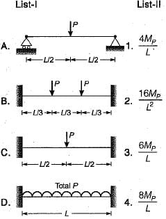
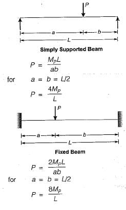
A load P is applied at the middle of a simply supported beam of span L. If the beam is made of ductile material, and Mp is the plastic moment, what is the ultimate value of P?- a)Mp/4L
- b)2Mp/L
- c)2.5Mp/L
- d)4 Mp/L
Correct answer is option 'D'. Can you explain this answer?
A load P is applied at the middle of a simply supported beam of span L. If the beam is made of ductile material, and Mp is the plastic moment, what is the ultimate value of P?
a)
Mp/4L
b)
2Mp/L
c)
2.5Mp/L
d)
4 Mp/L
|
|
Janhavi Datta answered |
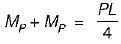
The simply supported beam is a determinate one, hence one plastic hinge will be required for its complete collapse. This plastic hinge will be,
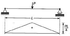
formed under the load. Hence the maximum bending moment can at the most reach to the plastic moment M
∴
formed under the load. Hence the maximum bending moment can at the most reach to the plastic moment M
p
.∴
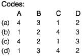
A prismatic beam (shape factor, $) fixed at both ends carries UDL throughout the span. What is the ratio of collapse load to yield load?- a)

- b)

- c)

- d)

Correct answer is option 'A'. Can you explain this answer?
A prismatic beam (shape factor, $) fixed at both ends carries UDL throughout the span. What is the ratio of collapse load to yield load?
a)
b)
c)
d)

|
Gladiators Channel answered |
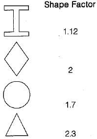
Find the shape factor of the thin ring of diameter D and thickness t.
The plastic section modulus for a rectangular section of width b and depth d is- a)bd2/3
- b)bd2/4
- c)bd2/6
- d)bd2/12
Correct answer is option 'B'. Can you explain this answer?
The plastic section modulus for a rectangular section of width b and depth d is
a)
bd2/3
b)
bd2/4
c)
bd2/6
d)
bd2/12
|
|
Kavya Mehta answered |
Plastic Section Modulus for Rectangular Section
Plastic section modulus is used to calculate the bending capacity of a cross-section of a structural member. In the case of a rectangular section, the plastic section modulus is given by:
Zp = bd2/4
where b is the width of the section and d is the depth of the section.
Explanation of the Formula
To understand the formula for plastic section modulus of a rectangular section, let's consider a beam that is subject to bending. When a beam is subjected to bending, the top and bottom fibers of the beam are in compression and tension, respectively. At some point, the stress in the extreme fibers reaches the yield strength of the material, and plastic deformation begins to occur.
The plastic section modulus is a measure of the ability of a cross-section to resist plastic deformation. It is defined as the ratio of the moment of inertia of the cross-section to the distance from the extreme fiber to the neutral axis. For a rectangular section, the distance from the extreme fiber to the neutral axis is equal to half the depth of the section, i.e., d/2.
The moment of inertia of a rectangular section is given by:
I = bd3/12
Substituting this expression into the formula for plastic section modulus gives:
Zp = I/(d/2) = bd3/12/(d/2) = bd2/4
Therefore, the plastic section modulus for a rectangular section of width b and depth d is given by:
Zp = bd2/4
Conclusion
The plastic section modulus for a rectangular section is an important parameter in the design of structural members. The formula for plastic section modulus of a rectangular section is derived based on the moment of inertia of the section and the distance from the extreme fiber to the neutral axis. The plastic section modulus is a measure of the ability of a cross-section to resist plastic deformation and is used to calculate the bending capacity of a structural member.
In a plastic analysis of structures, the segment between any two successive plastic hinges is assumed to deform as- a)A plastic material
- b)A rigid material
- c)An elastic material
- d)An inelastic material
Correct answer is option 'B'. Can you explain this answer?
In a plastic analysis of structures, the segment between any two successive plastic hinges is assumed to deform as
a)
A plastic material
b)
A rigid material
c)
An elastic material
d)
An inelastic material
|
|
Raghavendra Goyal answered |
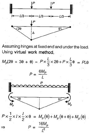
The initial slopes and deflections of the beam do not affect the virtual work equations. Thus the displacement diagram can be simplified to consists of straight and undefiected lines i.e. rigid deformation.
For steel structures proportioned using plastic design, the working load (dead load + imposed load) should be multiplied by which one of the following minimum load factor?- a)1.3
- b)1.5
- c)1.7
- d)2.0
Correct answer is option 'C'. Can you explain this answer?
For steel structures proportioned using plastic design, the working load (dead load + imposed load) should be multiplied by which one of the following minimum load factor?
a)
1.3
b)
1.5
c)
1.7
d)
2.0
|
|
Avinash Mehta answered |
For steel structures proportioned using plastic design, the working load (dead load + imposed load) should be multiplied by 1.7 minimum load factor.
The plastic design method is used to determine the structural capacity of steel members or frames. This method is based on the assumption that the structure has reached its ultimate capacity, and that any additional loads will cause permanent deformation of the structure.
In the plastic design method, a load factor is applied to the working load in order to ensure that the structure has sufficient strength to support the loads. The load factor is used to provide a safety factor for the structure to prevent overloading.
According to the relevant IS codes, for steel structures proportioned using plastic design, the minimum load factor is 1.7. This means that the working load should be multiplied by 1.7 in order to ensure that the structure has enough strength to support the loads. This safety factor ensure that the structure is able to withstand loads higher than the expected loads.
In a T-section shown in figure below, what is the distance of plastic neutral axis as measured down from top?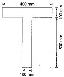
- a)100 mm
- b)150 mm
- c)200 mm
- d)300 mm
Correct answer is option 'B'. Can you explain this answer?
In a T-section shown in figure below, what is the distance of plastic neutral axis as measured down from top?
a)
100 mm
b)
150 mm
c)
200 mm
d)
300 mm
|
|
Ameya Roy answered |
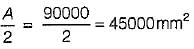
Total area, A = 400 x 100 + 100 x 500
= 90000 mm2
Thus the plastic neutral axis lies outside the flange because the flange area is only 40000 mm2.
Let the plastic neutral axis lies y mm below the junction of flange and web.
∴ y x 100 = 45000 - 40000
⇒ y = 50 mm
∴ Plastic neutral axis as measured from top of flange = 100 + y
= 100 + 50 = 150 mm
Consider the following assumptions made in the plastic theory
1. Distribution of strain across the section is linear
2. There is an axis of symmetry in the cross- section
3. The influence of normal and shearing forces is neglected
4. Strain energy stored due to elastic bending is ignoredWhich of these assumptions are correct?- a)1, 2 and 3
- b)1, 2 and 4
- c)1, 3 and 4
- d)1, 2, 3 and 4
Correct answer is option 'D'. Can you explain this answer?
Consider the following assumptions made in the plastic theory
1. Distribution of strain across the section is linear
2. There is an axis of symmetry in the cross- section
3. The influence of normal and shearing forces is neglected
4. Strain energy stored due to elastic bending is ignored
1. Distribution of strain across the section is linear
2. There is an axis of symmetry in the cross- section
3. The influence of normal and shearing forces is neglected
4. Strain energy stored due to elastic bending is ignored
Which of these assumptions are correct?
a)
1, 2 and 3
b)
1, 2 and 4
c)
1, 3 and 4
d)
1, 2, 3 and 4
|
|
Navya Saha answered |
Assumptions in Plastic Theory:
1. Distribution of strain across the section is linear
2. There is an axis of symmetry in the cross-section
3. The influence of normal and shearing forces is neglected
4. Strain energy stored due to elastic bending is ignored
Explanation:
1. Distribution of strain across the section is linear:
This assumption implies that the strain distribution across the section is assumed to be linear, which means that the strain varies linearly with the distance from the neutral axis. This assumption simplifies the analysis and allows for the determination of plastic moments and plastic section modulus.
2. There is an axis of symmetry in the cross-section:
This assumption assumes the presence of an axis of symmetry in the cross-section. The axis of symmetry divides the section into two equal halves, which simplifies the analysis and allows for the determination of plastic moments and plastic section modulus.
3. The influence of normal and shearing forces is neglected:
This assumption neglects the influence of normal and shearing forces on the behavior of the section. It assumes that only bending moments are present and these moments are the only significant factor in determining the plastic behavior of the section.
4. Strain energy stored due to elastic bending is ignored:
This assumption ignores the strain energy stored in the section due to elastic bending. It assumes that the section behaves plastically and does not consider the elastic response of the material. This assumption simplifies the analysis and allows for the determination of plastic moments and plastic section modulus.
Correct assumptions:
Based on the given options, the correct assumptions are:
- Distribution of strain across the section is linear
- There is an axis of symmetry in the cross-section
- The influence of normal and shearing forces is neglected
- Strain energy stored due to elastic bending is ignored
Therefore, the correct answer is option 'D' - 1, 2, 3, and 4.
Which of the following conditions is to be satisfied both in elastic and plastic analysis?- a)equilibrium condition
- b)yield condition
- c)plastic moment condition
- d)mechanism condition
Correct answer is option 'A'. Can you explain this answer?
Which of the following conditions is to be satisfied both in elastic and plastic analysis?
a)
equilibrium condition
b)
yield condition
c)
plastic moment condition
d)
mechanism condition

|
Om Pillai answered |
Equilibrium condition
The equilibrium condition is a fundamental requirement in both elastic and plastic analysis. It states that the sum of all forces acting on a structure must be zero, and the sum of all moments about any point must also be zero. This condition ensures that the structure is in a state of static equilibrium, meaning that it is not experiencing any external forces or moments that would cause it to move or rotate.
In elastic analysis, the equilibrium condition is used to determine the internal forces and moments within a structure based on the applied loads and the material properties. The analysis assumes that the structure behaves elastically, meaning that it deforms under the applied loads but returns to its original shape once the loads are removed. The equilibrium condition is used to solve for the internal forces and deformations in the structure.
In plastic analysis, the equilibrium condition is used to determine the collapse load of a structure. Plastic analysis assumes that the structure behaves plastically, meaning that it undergoes significant permanent deformation beyond its elastic limit. The equilibrium condition is used to determine the internal forces and moments at the collapse load, which is the maximum load that the structure can support before it becomes unstable.
Yield condition
The yield condition is a condition that must be satisfied in plastic analysis but not in elastic analysis. It states that the internal forces and moments in a structure must not exceed the yield strength of the material. When the yield condition is satisfied, the structure is considered to be in a state of plastic collapse.
The yield condition is used to determine the collapse load of a structure in plastic analysis. It ensures that the structure does not undergo excessive deformation or failure when subjected to the maximum load. If the internal forces and moments exceed the yield strength of the material, the structure will undergo plastic deformation and may fail.
Plastic moment condition
The plastic moment condition is another condition that must be satisfied in plastic analysis but not in elastic analysis. It states that the internal bending moment in a structural member at the collapse load must be equal to or greater than the plastic moment capacity of the section.
The plastic moment condition is used to determine the collapse load of a structure in plastic analysis. It ensures that the bending moment in the structural member does not exceed its plastic moment capacity, which is the maximum bending moment that the section can resist before it undergoes significant plastic deformation. If the bending moment exceeds the plastic moment capacity, the section will undergo plastic deformation and may fail.
Mechanism condition
The mechanism condition is not required to be satisfied in either elastic or plastic analysis. It is a condition that is used in the design of structures to ensure that they have sufficient redundancy and ductility to withstand unexpected loads or failures. The mechanism condition states that the structure should have multiple load paths and alternative load paths that can be activated in case of failure. This condition is not directly related to the equilibrium, yield, or plastic moment conditions, but it is important for the overall safety and performance of the structure.
In summary, the equilibrium condition is the only condition that is required to be satisfied in both elastic and plastic analysis. The yield condition, plastic moment condition, and mechanism condition are specific to plastic analysis and are not required in elastic analysis.
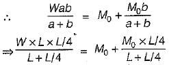
A propped cantilever beam of uniform moment capacity M0 is shown in figure below.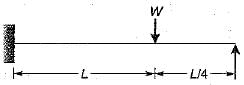 What is the collapse load W?
- a)

- b)

- c)

- d)

Correct answer is option 'C'. Can you explain this answer?
A propped cantilever beam of uniform moment capacity M0 is shown in figure below.
What is the collapse load W?
a)
b)
c)
d)
|
|
Lekshmi Das answered |
Number of plastic hinges required for complete collapse - r + 1
= (3 - 2) + 1 = 2
The plastic hinges will be formed under the load and at the fixed end of the beam respectively.
= (3 - 2) + 1 = 2
The plastic hinges will be formed under the load and at the fixed end of the beam respectively.
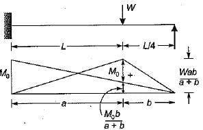
But a = L and b = L/4
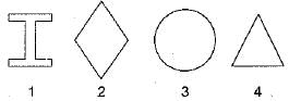
The shape factor for a solid circular section of diameter D is equal to- a)D/2π
- b)15/2π
- c)16/3π
- d)πD/8
Correct answer is option 'C'. Can you explain this answer?
The shape factor for a solid circular section of diameter D is equal to
a)
D/2π
b)
15/2π
c)
16/3π
d)
πD/8
|
|
Sreemoyee Chauhan answered |
B)1/4
c)1/2
d)4/π
The correct answer is c) 1/2.
The shape factor for a solid circular section is defined as the ratio of the area moment of inertia (I) to the section modulus (Z).
For a solid circular section, the area moment of inertia is given by:
I = πD^4/64
And the section modulus is given by:
Z = πD^3/32
Therefore, the shape factor is:
I/Z = (πD^4/64) / (πD^3/32) = 1/2
So, the correct answer is c) 1/2.
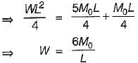
A continuous beam is loaded as shown in the figure below. Assuming a plastic moment capacity equal to Mp, the minimum load at which the beam would collapse is 
- a)4MP/L
- b)6MP/L
- c)8MP/L
- d)10MP/L
Correct answer is option 'B'. Can you explain this answer?
A continuous beam is loaded as shown in the figure below. Assuming a plastic moment capacity equal to Mp, the minimum load at which the beam would collapse is
a)
4MP/L
b)
6MP/L
c)
8MP/L
d)
10MP/L
|
|
Baishali Chopra answered |
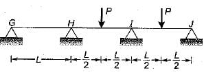
For collapse in IJ
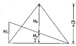
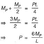
For collapse in HI
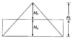
⇒ P = 8MP/L
∴ Minimum load for collapse = 6MP/L
The cross-sectional area and plastic section modulus of the given section are respectively
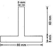
- a)600 mm2,10,000 mm3
- b)700 mm2, 8650 mm3
- c)600 mm2, 9750 mm3
- d)700 mm2,10,500 mm3
Correct answer is option 'C'. Can you explain this answer?
The cross-sectional area and plastic section modulus of the given section are respectively
a)
600 mm2,10,000 mm3
b)
700 mm2, 8650 mm3
c)
600 mm2, 9750 mm3
d)
700 mm2,10,500 mm3
|
|
Divya Kulkarni answered |
Total area, A = 5 x 60 + 5 x 60
= 600 mm2
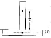
The centroids of half areas on either side of axis

Therefore plastic section modulus
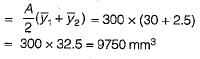
= 600 mm2
The centroids of half areas on either side of axis
Therefore plastic section modulus
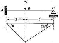
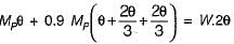
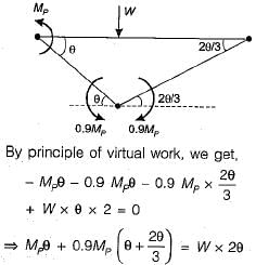
If a uniform beam shown in the figure below has the plastic moment capacity Mp for span AB and 0.9 Mp for span BC, what is the correct virtual work equation?
- a)
- b)
- c)
- d)
Correct answer is option 'C'. Can you explain this answer?
If a uniform beam shown in the figure below has the plastic moment capacity Mp for span AB and 0.9 Mp for span BC, what is the correct virtual work equation?
a)
b)
c)
d)
|
|
Jay Menon answered |
Total number of plastic hinges needed for complete collapse of the beam may be given as,
Number of plastic hinges,
= r + 1 = (3 - 2) + 1 = 2
Number of plastic hinges,
= r + 1 = (3 - 2) + 1 = 2
At the location of a plastic hinge,- a)radius of curvature is infinite
- b)curvature is infinite
- c)moment is infinite
- d)flexible stress in infinite
Correct answer is option 'B'. Can you explain this answer?
At the location of a plastic hinge,
a)
radius of curvature is infinite
b)
curvature is infinite
c)
moment is infinite
d)
flexible stress in infinite
|
|
Arya Menon answered |
The correct answer is option 'B' - curvature is infinite.
Explanation:
A plastic hinge is a phenomenon that occurs in structural elements when they undergo plastic deformation. It is a location where the material has yielded and the deformation becomes permanent. Plastic hinges usually occur in beams and columns under excessive loads or during extreme events like earthquakes.
Plastic Hinge and Curvature:
When a plastic hinge forms in a structural element, it indicates that the material has reached its plastic limit and will not regain its original shape. At the location of a plastic hinge, the curvature of the element becomes infinite.
Curvature is a measure of how much a curve deviates from being a straight line. It is defined as the reciprocal of the radius of curvature. In other words, curvature is inversely proportional to the radius of curvature.
At the location of a plastic hinge, the radius of curvature becomes zero because the material has yielded and undergone permanent deformation. Therefore, the curvature becomes infinite.
Significance of Infinite Curvature:
Infinite curvature at a plastic hinge signifies that the structural element has undergone significant deformation and has lost its ability to carry additional load. It indicates that the element has reached its ultimate capacity and cannot sustain any more load without further damage.
Other Options:
- Option 'A' - radius of curvature is infinite: This is incorrect because the radius of curvature becomes zero at a plastic hinge, not infinite.
- Option 'C' - moment is infinite: This is incorrect because the moment at a plastic hinge is not infinite. It is the bending moment that causes the plastic deformation and the formation of the hinge.
- Option 'D' - flexible stress in infinite: This is incorrect because the stress at a plastic hinge is not infinite. The material has reached its yield point and is subject to the yield stress, but it is not infinite.
In conclusion, the correct answer is option 'B' - curvature is infinite. At the location of a plastic hinge, the curvature becomes infinite, indicating significant plastic deformation and loss of load-carrying capacity.
Position of plastic hinge in the beam shown in figure subjected to collapse ioad will be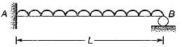
- a)at support A and at mid span
- b)at mid span and at support B
- c)at support A and within L/2 from B
- d)at mid span and within L/2 from B
Correct answer is option 'C'. Can you explain this answer?
Position of plastic hinge in the beam shown in figure subjected to collapse ioad will be
a)
at support A and at mid span
b)
at mid span and at support B
c)
at support A and within L/2 from B
d)
at mid span and within L/2 from B
|
|
Divya Mehta answered |
Because maximum bending moment develops at end A and between mid span and end B.
Chapter doubts & questions for Plastic Analysis - 6 Months Preparation for GATE Civil Engg 2025 is part of Civil Engineering (CE) exam preparation. The chapters have been prepared according to the Civil Engineering (CE) exam syllabus. The Chapter doubts & questions, notes, tests & MCQs are made for Civil Engineering (CE) 2025 Exam. Find important definitions, questions, notes, meanings, examples, exercises, MCQs and online tests here.
Chapter doubts & questions of Plastic Analysis - 6 Months Preparation for GATE Civil Engg in English & Hindi are available as part of Civil Engineering (CE) exam.
Download more important topics, notes, lectures and mock test series for Civil Engineering (CE) Exam by signing up for free.
6 Months Preparation for GATE Civil Engg
488 videos|1261 docs|878 tests
|
|
© EduRev
|
Education Revolution
|


|


Signup to see your scores
go up
within 7 days!
within 7 days!
Takes less than 10 seconds to signup