


All Exams >
Civil Engineering (CE) >
6 Months Preparation for GATE Civil Engg >
All Questions
All questions of Sub-surface investigations for Civil Engineering (CE) Exam
The split tube used in static cone penetration test, is commonly known as ______________- a)Split spoon sampler
- b)Split tube sampler
- c)Tube sampler
- d)All of the mentioned
Correct answer is option 'A'. Can you explain this answer?
The split tube used in static cone penetration test, is commonly known as ______________
a)
Split spoon sampler
b)
Split tube sampler
c)
Tube sampler
d)
All of the mentioned

|
Devansh Banerjee answered |
Split Spoon Sampler in Static Cone Penetration Test:
The split tube used in static cone penetration test is commonly known as a Split spoon sampler. This tool is specifically designed to collect undisturbed soil samples during penetration tests.
Key Points:
- Function: The split spoon sampler is used to collect samples of soil at various depths as the cone penetrometer is pushed into the ground.
- Design: The split tube has a cutting shoe at the bottom to facilitate penetration into the soil. It is split lengthwise to allow the soil sample to be easily extracted once the sampler is pulled out of the ground.
- Usage: During the static cone penetration test, the split spoon sampler is pushed into the ground at the desired depth, and then extracted to obtain a sample for analysis.
- Advantages: The split spoon sampler helps in obtaining relatively undisturbed soil samples, which are crucial for accurate analysis of soil properties.
- Limitations: The split tube sampler is limited in terms of the size of the sample it can collect and the depths it can reach compared to other sampling methods.
In summary, the split spoon sampler plays a vital role in the static cone penetration test by providing undisturbed soil samples for analysis, thus aiding in the evaluation of soil properties and geotechnical assessments.

For a c-φ soil, Housel suggested which of the following expression?- a)Q = A .q + P .s
- b)Q = A .q
- c)q f = M + N( BF/B p )
- d)All of the mentioned
Correct answer is option 'A'. Can you explain this answer?
For a c-φ soil, Housel suggested which of the following expression?
a)
Q = A .q + P .s
b)
Q = A .q
c)
q f = M + N( BF/B p )
d)
All of the mentioned
|
|
Sanvi Kapoor answered |
In 1929, Housel suggested the following expression for a c-φ soil:
Q = A .q + P .s
Where, Q = total load on bearing area;
P = perimeter of footing;
S = perimeter shear;
A = contact area of footing or plate.
Q = A .q + P .s
Where, Q = total load on bearing area;
P = perimeter of footing;
S = perimeter shear;
A = contact area of footing or plate.
From the plate load test, the ultimate bearing capacity of plate of size 0.3 m × 0.3 m on sand deposit is observed to be 200 kN/m2, the ultimate bearing capacity of a footing of size 1.5 m × 1.5 m will be:- a)200 kN/m2
- b)1000 kN/m2
- c)500 kN/m2
- d)2000 kN/m2
Correct answer is option 'B'. Can you explain this answer?
From the plate load test, the ultimate bearing capacity of plate of size 0.3 m × 0.3 m on sand deposit is observed to be 200 kN/m2, the ultimate bearing capacity of a footing of size 1.5 m × 1.5 m will be:
a)
200 kN/m2
b)
1000 kN/m2
c)
500 kN/m2
d)
2000 kN/m2

|
Sravya Tiwari answered |
Calculation:
The ultimate bearing capacity of a plate of size 0.3 m x 0.3 m on sand deposit is 200 kN/m2.
Step 1: Determine the area of the footing
Given that the footing size is 1.5 m x 1.5 m
Area = Length x Width = 1.5 m x 1.5 m = 2.25 m2
Step 2: Calculate the ultimate bearing capacity of the footing
Ultimate bearing capacity of the plate = 200 kN/m2
Ultimate bearing capacity of the footing = Ultimate bearing capacity of the plate x Area of the footing
Ultimate bearing capacity of the footing = 200 kN/m2 x 2.25 m2 = 450 kN
Hence, the ultimate bearing capacity of a footing of size 1.5 m x 1.5 m on sand deposit will be 450 kN or 450 kN/m2. Since the options are not in the same units, we convert 450 kN to kN/m2 by dividing by the area of the footing:
450 kN / 2.25 m2 = 200 kN/m2
Therefore, the ultimate bearing capacity of the footing will be 200 kN/m2, which corresponds to option (b).
The two commonly used penetration tests are ______- a)Standard penetration test
- b)Cone penetration test
- c)All of the mentioned
- d)None of the mentioned
Correct answer is option 'C'. Can you explain this answer?
The two commonly used penetration tests are ______
a)
Standard penetration test
b)
Cone penetration test
c)
All of the mentioned
d)
None of the mentioned
|
|
Sudhir Patel answered |
According to Indian standard, the two commonly used penetration tests are static cone penetration test and standard penetration test.
The plate load test is essentially a ___________- a)Laboratory test
- b)Field test
- c)Graphical method analysis
- d)None of the mentioned
Correct answer is option 'B'. Can you explain this answer?
The plate load test is essentially a ___________
a)
Laboratory test
b)
Field test
c)
Graphical method analysis
d)
None of the mentioned
|
|
Gitanjali Chauhan answered |
Plate Load Test
The plate load test is a field test used to determine the bearing capacity and settlement of a soil. It involves applying a load to a plate placed on the ground surface and measuring the resulting settlement. The test is typically performed to assess the suitability of the soil for construction purposes, such as the design of foundation systems.
Field Test
The correct answer is option 'B' - field test. The plate load test is conducted in the field, directly on the ground surface where the construction will take place. It is performed to evaluate the in-situ behavior of the soil under load, providing more accurate and realistic results compared to laboratory tests.
Laboratory Test
While laboratory tests are commonly used to determine soil properties, they may not always reflect the actual behavior of the soil in the field. The plate load test allows for the assessment of the soil's response to load under realistic conditions, taking into account factors such as soil layering, moisture content, and compaction.
Graphical Method Analysis
The plate load test involves measuring the settlement of the plate as load is applied. The test data is typically plotted on a graph, where the load is plotted on the x-axis and the settlement on the y-axis. The resulting curve can provide insights into the soil's behavior, such as the elastic and plastic deformation characteristics.
Conclusion
In conclusion, the plate load test is a field test used to evaluate the bearing capacity and settlement of a soil. It is conducted directly on the ground surface and provides more realistic results compared to laboratory tests. The test data is typically analyzed using graphical methods to understand the soil's behavior under load. Therefore, the correct answer is option 'B' - field test.
The time taken to drill a hole of diameter 25 mm in a 30 mm thick steel plate with a feed of 1 mm/rev and the drill spindle speed being 60 rpm is _________ seconds.- a)20
- b)30
- c)40
- d)50
Correct answer is option 'B'. Can you explain this answer?
The time taken to drill a hole of diameter 25 mm in a 30 mm thick steel plate with a feed of 1 mm/rev and the drill spindle speed being 60 rpm is _________ seconds.
a)
20
b)
30
c)
40
d)
50
|
|
Akshat Datta answered |
To calculate the time taken to drill a hole in a steel plate, we need to consider the drilling parameters such as the diameter of the hole, the thickness of the plate, the feed rate, and the spindle speed.
Given:
Diameter of the hole (D) = 25 mm
Thickness of the plate (T) = 30 mm
Feed rate (f) = 1 mm/rev
Spindle speed (N) = 60 rpm
To calculate the time taken to drill the hole, we can use the formula:
Time (t) = (π * D) / (f * N)
Now, let's substitute the given values into the formula:
t = (π * 25) / (1 * 60)
t = (3.14 * 25) / 60
t = 78.5 / 60
t = 1.308 seconds (approximately)
Therefore, the time taken to drill a hole of diameter 25 mm in a 30 mm thick steel plate with a feed of 1 mm/rev and a drill spindle speed of 60 rpm is approximately 1.308 seconds.
So, the correct answer is option B) 30 seconds.
Let's summarize the given values and the calculated time:
Given:
Diameter of the hole (D) = 25 mm
Thickness of the plate (T) = 30 mm
Feed rate (f) = 1 mm/rev
Spindle speed (N) = 60 rpm
Calculated:
Time taken (t) = 1.308 seconds (approximately)
Answer: The correct option is B) 30 seconds.
Given:
Diameter of the hole (D) = 25 mm
Thickness of the plate (T) = 30 mm
Feed rate (f) = 1 mm/rev
Spindle speed (N) = 60 rpm
To calculate the time taken to drill the hole, we can use the formula:
Time (t) = (π * D) / (f * N)
Now, let's substitute the given values into the formula:
t = (π * 25) / (1 * 60)
t = (3.14 * 25) / 60
t = 78.5 / 60
t = 1.308 seconds (approximately)
Therefore, the time taken to drill a hole of diameter 25 mm in a 30 mm thick steel plate with a feed of 1 mm/rev and a drill spindle speed of 60 rpm is approximately 1.308 seconds.
So, the correct answer is option B) 30 seconds.
Let's summarize the given values and the calculated time:
Given:
Diameter of the hole (D) = 25 mm
Thickness of the plate (T) = 30 mm
Feed rate (f) = 1 mm/rev
Spindle speed (N) = 60 rpm
Calculated:
Time taken (t) = 1.308 seconds (approximately)
Answer: The correct option is B) 30 seconds.
The value of factor of safety used, for finding safe bearing capacity is __________- a)2.5
- b)2
- c)4
- d)3
Correct answer is option 'B'. Can you explain this answer?
The value of factor of safety used, for finding safe bearing capacity is __________
a)
2.5
b)
2
c)
4
d)
3
|
|
Divya Kulkarni answered |
Factor of Safety for Safe Bearing Capacity
The factor of safety is used in geotechnical engineering to ensure that the stress applied to soil is well within the safe limit. The factor of safety is the ratio of the ultimate or maximum stress that the soil can bear to the actual stress applied. In other words, the factor of safety is the margin of safety that is used to prevent failure of the soil.
Safe Bearing Capacity
The safe bearing capacity of soil refers to the maximum load that can be applied to the soil without failure or excessive settlement. The safe bearing capacity is determined by conducting soil tests and analyzing the soil properties. The safe bearing capacity is an important factor in the design of foundations and structures.
Value of Factor of Safety for Safe Bearing Capacity
The value of the factor of safety used for finding the safe bearing capacity depends on the type of soil, the load that is applied and the level of risk that is acceptable. Generally, a factor of safety of 2 is used for normal soil conditions. However, for more critical structures, a factor of safety of 2.5 or 3 may be used.
Answer:
The correct option is B, which states that the value of factor of safety used for finding safe bearing capacity is 2.
The cone resistance qc, for sandy silt type of soil is __________- a)3.5
- b)6
- c)2
- d)5
Correct answer is option 'C'. Can you explain this answer?
The cone resistance qc, for sandy silt type of soil is __________
a)
3.5
b)
6
c)
2
d)
5
|
|
Kavya Mehta answered |
Explanation:
Soil Type:
- The sandy silt type of soil is a common type of soil found in various locations.
Cone Resistance:
- Cone resistance (qc) is a measure of the resistance to penetration of a cone into the soil.
- It is an important parameter in geotechnical engineering for determining soil properties.
Value for Sandy Silt Soil:
- For sandy silt soil, the typical value of cone resistance (qc) is around 2.
Therefore, the correct answer to the question is option 'C' - 2.
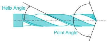
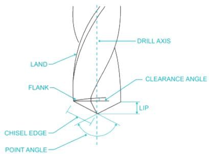
What is the point angle of a twist drill for general purpose work? - a)108°
- b)118°
- c)120°
- d)181°
Correct answer is option 'B'. Can you explain this answer?
What is the point angle of a twist drill for general purpose work?
a)
108°
b)
118°
c)
120°
d)
181°

|
Lekshmi Kaur answered |
Point Angle of a Twist Drill for General Purpose Work
Twist drills are commonly used in various machining operations, including drilling holes in different materials. The point angle of a twist drill is an important parameter that determines the efficiency and effectiveness of the drilling process.
Correct Answer: 118°
Explanation:
- The point angle of a twist drill for general purpose work is typically 118°.
- This angle is considered to be a standard point angle for most drilling applications.
- A 118° point angle is versatile and can be used for drilling a wide range of materials, including metals, plastics, and wood.
- It provides a good balance between cutting efficiency and strength, making it suitable for general drilling tasks.
- Using the correct point angle helps in achieving accurate and precise holes while reducing the chances of drill breakage or damage to the workpiece.
- While other point angles like 108° or 120° can also be used for specific applications, a 118° point angle is widely accepted for general purpose work in various industries.
In conclusion, the point angle of 118° is commonly used for general purpose work with twist drills due to its versatility and effectiveness in drilling different materials.
What is the maximum size of drill can be hold in sensitive drilling machine? - a)10.0 mm
- b)12.5 mm
- c)15.0 mm
- d)20.0 mm
Correct answer is option 'C'. Can you explain this answer?
What is the maximum size of drill can be hold in sensitive drilling machine?
a)
10.0 mm
b)
12.5 mm
c)
15.0 mm
d)
20.0 mm
|
|
Nilesh Verma answered |
The maximum size of drill that can be held in a sensitive drilling machine is 15.0 mm.
Explanation:
A sensitive drilling machine, also known as a bench drilling machine, is a small and compact machine used for precision drilling operations. It is designed for drilling small holes in materials such as metal, plastic, and wood.
When it comes to the maximum size of drill that can be held in a sensitive drilling machine, it depends on the machine's specifications and capabilities. The maximum size is determined by the diameter of the drill chuck, which is the part of the machine that holds the drill bit securely in place.
In this case, the maximum size of drill that can be held in the sensitive drilling machine is 15.0 mm. This means that the drill chuck is designed to accommodate drill bits with a maximum diameter of 15.0 mm.
The size of the drill is an important consideration as it affects the stability and performance of the drilling operation. Using a drill bit that is too large for the machine can put excessive strain on the machine's motor and may result in poor drilling performance or even damage to the machine.
It is always recommended to refer to the machine's manual or specifications provided by the manufacturer to determine the maximum size of drill that can be used. This ensures safe and efficient drilling operations while maximizing the capabilities of the machine.
In summary, the maximum size of drill that can be held in a sensitive drilling machine is 15.0 mm. It is important to follow the manufacturer's guidelines and specifications to ensure safe and effective drilling operations.
The expression for C n as given by Lio and Whitman is _____________- a)C n = √(σ’)
- b)C n = √(100/σ’)
- c)C n = 0.77log10(2000/σ’)
- d)None of the mentioned
Correct answer is option 'B'. Can you explain this answer?
The expression for C n as given by Lio and Whitman is _____________
a)
C n = √(σ’)
b)
C n = √(100/σ’)
c)
C n = 0.77log10(2000/σ’)
d)
None of the mentioned
|
|
Sudhir Patel answered |
In 1986, Lio and Whitman gave the following expression for
Normalizing factor C n:
C n = √ (100/σ’).
Normalizing factor C n:
C n = √ (100/σ’).
The plate load test consists in loading a rigid plate at the _________- a)Base of the footing
- b)Bottom of the construction
- c)Foundation level
- d)All of the mentioned
Correct answer is option 'C'. Can you explain this answer?
The plate load test consists in loading a rigid plate at the _________
a)
Base of the footing
b)
Bottom of the construction
c)
Foundation level
d)
All of the mentioned
|
|
Raghavendra Goyal answered |
The plate load test is a commonly used method in geotechnical engineering to determine the bearing capacity and settlement characteristics of soil. It involves applying a known load to a rigid plate placed at the foundation level of a structure. The correct answer to the question is option 'C', which states that the plate load test is conducted at the foundation level.
Explanation:
1. Purpose of the Plate Load Test:
The plate load test is performed to assess the load-bearing capacity of the soil beneath a proposed structure. It helps in determining the safe design load for the foundation and predicting the settlement of the structure.
2. Test Setup:
During the plate load test, a rigid plate (typically made of steel or concrete) is placed at the foundation level. The plate is usually square or circular in shape and has a known area. It is then loaded with a known load using a hydraulic jack or any other suitable loading mechanism.
3. Load Application:
The load is incrementally applied to the plate in steps, and the corresponding settlement of the plate is measured at each load increment. The load is increased until the desired load capacity or a pre-defined settlement criterion is reached.
4. Measurement of Settlement:
The settlement of the plate is measured using displacement transducers, dial gauges, or other suitable instruments. The settlement readings are recorded at regular intervals until the desired load capacity is achieved.
5. Calculation of Bearing Capacity:
Based on the load applied and the corresponding settlement readings, the bearing capacity of the soil can be calculated. The bearing capacity is determined by dividing the applied load by the plate area. The settlement data is also used to estimate the settlement characteristics of the soil.
6. Interpretation of Results:
The results obtained from the plate load test provide valuable information about the soil's strength and its ability to support the intended structure. The data can be used to optimize the foundation design and ensure the structural stability of the building.
In conclusion, the plate load test is conducted at the foundation level to evaluate the bearing capacity and settlement characteristics of the soil. This test helps in determining the safe design load for the foundation and predicting the settlement of the structure.
For harder materials, the helix angle of the drill is- a)Less than 45 degree
- b)Equal to 45 degree
- c)Between 45 to 60 degree
- d)Between 60 to 90 degree
Correct answer is option 'A'. Can you explain this answer?
For harder materials, the helix angle of the drill is
a)
Less than 45 degree
b)
Equal to 45 degree
c)
Between 45 to 60 degree
d)
Between 60 to 90 degree
|
|
Sudhir Patel answered |
The helix angle is the angle between the leading edge of the land and the axis of the drill. Sometimes it is also called a spiral angle.
- The helix results in a positive cutting rake. This angle is equivalent to the back rake angle of a single-point cutting tool.
- The usual range of helix angle used in the drill is 20° to 35°.
- Large helix angle 45° to 60° suitable for deep holes and softer work materials.
- The small helix angle of less than 45° is suitable for harder and stronger materials.
- Zero helix angles are used in spade drills for high production drilling, micro‐drilling, and hard work materials.
Important Points
- An increase in helix angle is given for more quick removal of chips but a decrease in helix angle will give greater strength of cutting edges.
- The larger the value of helix angle lesser will be the power required in drilling.
Low helix angle drills are used for drilling holes in- a)Plastics
- b)Copper
- c)Cast steel
- d)Carbon steel
Correct answer is option 'A'. Can you explain this answer?
Low helix angle drills are used for drilling holes in
a)
Plastics
b)
Copper
c)
Cast steel
d)
Carbon steel
|
|
Sudhir Patel answered |
Helix angle
- It is the angle formed by the leading edge of the land with a plane having the axis of the drill.
- Its usual value is 30°.
- The low-helix drill was developed primarily to drill brass and other thin materials like plastics. Because of its design, the low-helix drill can remove the larger volume of chips formed by high rates of penetration.
- High helix-drills are designed for drilling deep holes in aluminium, copper, die-cast material, and other metals where the chips have a tendency to jam in a hole. The angles vary between (35° - 45°).
The observed value of N in static cone penetration test is corrected by _________- a)Overburden and Dilatancy /submergence
- b)Effective pressure
- c)None of the mentioned
- d)All of the mentioned
Correct answer is option 'A'. Can you explain this answer?
The observed value of N in static cone penetration test is corrected by _________
a)
Overburden and Dilatancy /submergence
b)
Effective pressure
c)
None of the mentioned
d)
All of the mentioned
|
|
Naina Das answered |
Understanding N Value in Static Cone Penetration Test
The static cone penetration test (CPT) is widely used in geotechnical engineering to assess soil properties. The observed value of N, which represents the cone resistance, often needs correction to reflect more accurate soil behavior under various conditions.
Corrections for Overburden Pressure
- The overburden pressure affects the effective stress in the soil.
- As depth increases, the weight of the overlying material increases, which can lead to higher cone penetration resistance.
- Correcting for overburden pressure helps in comparing cone resistance values at different depths accurately.
Dilatancy / Submergence Effects
- Dilatancy refers to the volume change observed in granular soils when they are subjected to shear stress.
- When soils are submerged, their effective stress changes, which can also alter the cone resistance readings.
- Adjusting the N value for these effects provides a more reliable assessment of soil behavior under varying conditions.
Conclusion: Importance of Corrections
- By correcting the observed N value for overburden pressure and dilatancy/submergence, engineers can better understand soil strength and behavior.
- This ensures safer and more effective designs in civil engineering projects.
Therefore, the correct answer to the question is option 'A', as it encompasses both critical correction factors necessary for accurate interpretations of the CPT results.
The size of bearing plate, which used in plate load test varies from ___________- a)300 to 750 mm
- b)25 to 100 mm
- c)100 to 300 mm
- d)25 to 300 mm
Correct answer is option 'A'. Can you explain this answer?
The size of bearing plate, which used in plate load test varies from ___________
a)
300 to 750 mm
b)
25 to 100 mm
c)
100 to 300 mm
d)
25 to 300 mm
|
|
Sanvi Kapoor answered |
The bearing plate used varies in size from 300 to 750 mm with a chequered or grooved bottom.
The standard penetration test is useful to measure- a)Consistency of clays
- b)Shear strength of soft clays
- c)Shear strength of sands
- d)Shear strength of stiff clay
Correct answer is option 'C'. Can you explain this answer?
The standard penetration test is useful to measure
a)
Consistency of clays
b)
Shear strength of soft clays
c)
Shear strength of sands
d)
Shear strength of stiff clay
|
|
Sudhir Patel answered |
Standard Penetration Test (SPT):
- It is specially used for cohesionless soils. It is used to determine the relative density and the angle of shearing resistance of cohesionless soils.
- It can also be used to determine the unconfined compressive strength of cohesive soils.
- The standard penetration number is equal to the number of blows required for 300 mm of penetration beyond a seating drive of 150 mm.
- If the number of blows for 150 mm drive exceeds 50, it is taken as refusal and the test is discontinued.
- Hence the standard penetration test is useful to measure the angle of shearing resistance of cohesionless soils, i.e Shear strength of sands.
Important Points
Some of the other methods for in-situ site exploration are
Some of the other methods for in-situ site exploration are
- Pressure Meter Test (PMT)
- Static Cone Penetration Test (SCPT)
- Vane Shear Test (VST)
The bearing plate used in plate load test is in the shape of __________- a)Square
- b)Rectangular and Circular
- c)None of the mentioned
- d)All of the mentioned
Correct answer is option 'B'. Can you explain this answer?
The bearing plate used in plate load test is in the shape of __________
a)
Square
b)
Rectangular and Circular
c)
None of the mentioned
d)
All of the mentioned
|
|
Sanya Agarwal answered |
The bearing plate is either circular or square, made of mild steel of not less than 25 mm in thickness.
Which drilling machine is capable of drilling upto 12.5 mm diameter?- a)Pillar drilling machine
- b)Radial drilling machine
- c)Column drilling machine
- d)Sensitive drilling machine
Correct answer is option 'D'. Can you explain this answer?
Which drilling machine is capable of drilling upto 12.5 mm diameter?
a)
Pillar drilling machine
b)
Radial drilling machine
c)
Column drilling machine
d)
Sensitive drilling machine
|
|
Sudhir Patel answered |
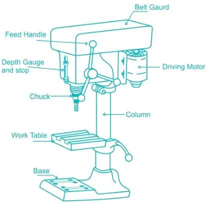
Drilling machine:
- The drilling machine is one of the most important machine tools in a workshop and is second to lathe. It was primarily designed to originate a hole. Drilling machines are made in many different types and sizes, each designed to handle a class of work or specific job to the best advantage.
The different types of drilling machines are:
- Portable drilling machine
- Sensitive drilling machine
- Upright drilling machine
- Radial drilling machine
- Gang drilling machine
- Multiple spindle drilling machine
- Automatic drilling machine
- Deep hole drilling machine
Sensitive Drilling Machine:
- The sensitive drilling machine is a small machine designed for drilling a small hole at high speed in light jobs, the base of the machine may be mounted on a bench or on the floor.
- The maximum size of drill that can be held in a sensitive drilling machine is 12.5 mm.
- It consists of a vertical column, a horizontal table, a head supporting the motor and driving mechanism, and a vertical spindle for driving and rotating the drill.
- There is no arrangement for any automatic feed of the drill spindle.
- The drill is fed into the work by purely hand control. High-speed and hand feed are necessary for drilling small holes.
- High speeds are necessary to attain the required cutting speed by a small-diameter drill.
- Hand feed permits the operator to feel or sense the progress of the drill into the work so that the drill becomes worn out or jams on any account, the pressure on the drill may be released immediately to prevent it from breaking.
The values derived from penetration tests can be used for finding ____________- a)Depth of hard stratum and Strength of soil
- b)Soil saturation
- c)None of the mentioned
- d)All of the mentioned
Correct answer is option 'A'. Can you explain this answer?
The values derived from penetration tests can be used for finding ____________
a)
Depth of hard stratum and Strength of soil
b)
Soil saturation
c)
None of the mentioned
d)
All of the mentioned
|
|
Sudhir Patel answered |
The penetration test are useful for general exploration of erratic soil profiles, for finding depth to bed rock or hard stratum, and to have an approximation indication of the strength and other properties of soils.
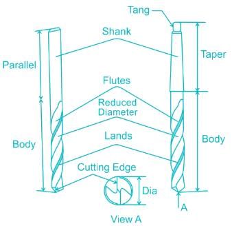
What is the maximum size of parallel shank twist drill?- a)10 mm
- b)11 mm
- c)12 mm
- d)13 mm
Correct answer is option 'D'. Can you explain this answer?
What is the maximum size of parallel shank twist drill?
a)
10 mm
b)
11 mm
c)
12 mm
d)
13 mm
|
|
Jithin Choudhury answered |
The maximum size of a parallel shank twist drill is 13 mm.
Explanation:
A parallel shank twist drill is a type of drill bit that is commonly used in various drilling applications. It consists of a cylindrical shank with two flutes that spiral around the body of the drill bit. The flutes are designed to remove the material as the drill bit rotates, allowing it to create a hole in the workpiece.
The size of a parallel shank twist drill is determined by its diameter, which is measured in millimeters (mm). The maximum size refers to the largest diameter available for this type of drill bit.
Key Points:
- A parallel shank twist drill is used for drilling holes in materials such as wood, metal, and plastic.
- The drill bit is inserted into a drill chuck or collet and secured in place before drilling.
- The diameter of the drill bit determines the size of the hole it can create.
- Smaller diameters are used for drilling smaller holes, while larger diameters are used for drilling larger holes.
- The maximum size of a parallel shank twist drill is 13 mm, which means it can create holes with a diameter of up to 13 mm.
- It is important to use the right size drill bit for the desired hole size to ensure accuracy and efficiency.
- Using a drill bit that is too small may result in a hole that is too small or requires excessive force to create.
- On the other hand, using a drill bit that is too large may result in a hole that is too large or causes damage to the workpiece.
- It is recommended to refer to the manufacturer's guidelines or consult a drilling chart to determine the appropriate drill bit size for a specific application.
In conclusion, the maximum size of a parallel shank twist drill is 13 mm, which indicates the largest diameter available for this type of drill bit.
The settlement of the plate in a load test is measured with the help of _________- a)Sensitive dial gauges
- b)Test plate
- c)Measuring unit
- d)Datum bar
Correct answer is option 'A'. Can you explain this answer?
The settlement of the plate in a load test is measured with the help of _________
a)
Sensitive dial gauges
b)
Test plate
c)
Measuring unit
d)
Datum bar

|
Raksha Nair answered |
Measurement of Settlement in Load Test
Measuring settlement in a load test is crucial for determining the behavior of the soil under the applied load. The settlement of the plate can be accurately measured using sensitive dial gauges.
Sensitive Dial Gauges
- Sensitive dial gauges are devices used to measure small displacements with high precision.
- These gauges have a pointer that moves along a scale, allowing for accurate readings of settlement.
- The sensitivity of these gauges is essential for detecting even minor settlements during the load test.
Procedure
- The sensitive dial gauge is placed in contact with the test plate or the surface being monitored for settlement.
- As the load is applied, the settlement of the plate causes the dial gauge to move, indicating the amount of settlement that has occurred.
- Multiple readings are taken at different intervals to track the settlement over time accurately.
Accuracy
- The use of sensitive dial gauges ensures that even the smallest settlement can be detected and measured.
- This accuracy is crucial for assessing the stability and load-bearing capacity of the soil under consideration.
In conclusion, sensitive dial gauges are essential tools for measuring settlement in load tests accurately. Their high precision and sensitivity allow engineers to gather reliable data on the behavior of soil under various loading conditions.
The cone test is useful in determining the bearing capacity of ___________- a)Cohesion less soil and Fine sand
- b)Clay soil
- c)None of the mentioned
- d)All of the mentioned
Correct answer is option 'A'. Can you explain this answer?
The cone test is useful in determining the bearing capacity of ___________
a)
Cohesion less soil and Fine sand
b)
Clay soil
c)
None of the mentioned
d)
All of the mentioned
|
|
Rounak Saini answered |
The cone test, also known as the cone penetration test (CPT), is a widely used in-situ testing method in geotechnical engineering. It involves pushing a cone-shaped penetrometer into the ground and measuring the resistance encountered. The cone test is primarily used to determine the bearing capacity of cohesionless soil and fine sand.
Cohesionless soil and fine sand are types of soils that do not have any cohesive properties. They are composed of loose particles that do not stick together. These types of soils are commonly found in coastal areas, riverbanks, and deserts. Due to their loose nature, they have different mechanical properties compared to cohesive soils such as clay.
Here are the reasons why the cone test is useful in determining the bearing capacity of cohesionless soil and fine sand:
1. Penetration Resistance: The cone penetrometer measures the resistance encountered as it is pushed into the ground. In cohesionless soil and fine sand, the resistance is primarily due to the friction between the cone and the soil particles. The higher the resistance, the denser the soil and the greater its bearing capacity.
2. Friction Ratio: The cone test also provides information about the friction ratio, which is the ratio of the skin friction to the cone tip resistance. In cohesionless soil and fine sand, the friction ratio is an important parameter for determining the soil's shear strength and bearing capacity.
3. Soil Classification: The cone test can also be used to classify the type of soil encountered. For example, the cone resistance and friction ratio values can be compared to standardized charts or correlations to determine whether the soil is a cohesionless soil or fine sand.
4. Design Parameters: The results of the cone test can be used to determine important design parameters for geotechnical engineering projects. These parameters include the allowable bearing capacity, foundation design, and settlement analysis.
In conclusion, the cone test is a useful method for determining the bearing capacity of cohesionless soil and fine sand. It provides valuable information about the soil's mechanical properties, friction ratio, and classification, which are essential for geotechnical engineering design and analysis.
Correction for increasing effective overburden pressure have been proposed by ___________- a)Gibbs and Holtz
- b)Peck
- c)Thornburn
- d)All of the mentioned
Correct answer is option 'D'. Can you explain this answer?
Correction for increasing effective overburden pressure have been proposed by ___________
a)
Gibbs and Holtz
b)
Peck
c)
Thornburn
d)
All of the mentioned
|
|
Sudhir Patel answered |
For a constant density index, the N value increase with increasing effective overburden pressure for which correction have been proposed by Gibbs and Holtz, peck, Thornburn, Whitman and others.
The machining time for drilling process is calculated by:
(Where L = Length of axial travel in mm; N = rpm of the drill; f = feed per rev in mm)- a)

- b)

- c)

- d)

Correct answer is option 'B'. Can you explain this answer?
The machining time for drilling process is calculated by:
(Where L = Length of axial travel in mm; N = rpm of the drill; f = feed per rev in mm)
(Where L = Length of axial travel in mm; N = rpm of the drill; f = feed per rev in mm)
a)
b)
c)
d)
|
|
Sudhir Patel answered |
Machining time for drilling:
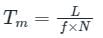
D = diameter, N = speed in rpm of the drill, L = Length of axial travel in mm, f = feed
D = diameter, N = speed in rpm of the drill, L = Length of axial travel in mm, f = feed
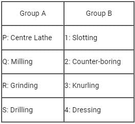
Match the Machine Tools (Group A) with the probable Operations (Group B):
- a)P-1, Q-2, R-4, S-3
- b)P-2, Q-1, R-4, S-3
- c)P-3, Q-1, R-4, S-2
- d)P-3, Q-4, R-2, S-1
Correct answer is option 'C'. Can you explain this answer?
Match the Machine Tools (Group A) with the probable Operations (Group B):
a)
P-1, Q-2, R-4, S-3
b)
P-2, Q-1, R-4, S-3
c)
P-3, Q-1, R-4, S-2
d)
P-3, Q-4, R-2, S-1
|
|
Sudhir Patel answered |
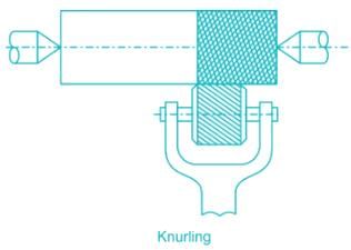
Centre Lathe → Knurling
Milling → Slotting
Grinding → Dressing
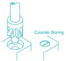
Drilling → Counter-boring
Knurling
Knurling is the operation of producing a straight-lined, diamond-shaped pattern or cross lined pattern on a cylindrical external surface by pressing a tool called knurling tool. Knurling is not a cutting operation but it is a forming operation.
A lathe is used for many operations such as turning, threading, facing, grooving, Knurling, Chamfering, centre drilling
Counter - boring
Counter - boring is an operation of enlarging a hole to a given depth, to house heads of socket heads or cap screws with the help of a counterbore tool.
Dressing:
When the sharpness of grinding wheel becomes dull because of glazing and loading, dulled grains and chips are removed (crushed or fallen) with a proper dressing tool to make sharp cutting edges.
The dressing is the operation of cleaning and restoring the sharpness of the wheel face that has become dull or has lost some of its cutting ability because of loading and glazing.
Slot Milling:
Slot milling is an operation of producing slots like T - slots, plain slots, dovetail slots etc.
Milling → Slotting
Grinding → Dressing
Drilling → Counter-boring
Knurling
Knurling is the operation of producing a straight-lined, diamond-shaped pattern or cross lined pattern on a cylindrical external surface by pressing a tool called knurling tool. Knurling is not a cutting operation but it is a forming operation.
A lathe is used for many operations such as turning, threading, facing, grooving, Knurling, Chamfering, centre drilling
Counter - boring
Counter - boring is an operation of enlarging a hole to a given depth, to house heads of socket heads or cap screws with the help of a counterbore tool.
Dressing:
When the sharpness of grinding wheel becomes dull because of glazing and loading, dulled grains and chips are removed (crushed or fallen) with a proper dressing tool to make sharp cutting edges.
The dressing is the operation of cleaning and restoring the sharpness of the wheel face that has become dull or has lost some of its cutting ability because of loading and glazing.
Slot Milling:
Slot milling is an operation of producing slots like T - slots, plain slots, dovetail slots etc.
The loading to the test plate is applied with __________- a)Fluid tube
- b)Hydraulic jack
- c)Sand bags
- d)Cross-joists
Correct answer is option 'B'. Can you explain this answer?
The loading to the test plate is applied with __________
a)
Fluid tube
b)
Hydraulic jack
c)
Sand bags
d)
Cross-joists
|
|
Sanya Agarwal answered |
The loading to the test plate may be applied with the help of a hydraulic jack. The reaction of the hydraulic jack may be borne by either any of gravity loading methodor reaction truss method.
A seating pressure of ___________ is applied on the plate before starting the load test.- a)70 g/cm2
- b)30 g/cm2
- c)50 g/cm2
- d)100 g/cm2
Correct answer is option 'A'. Can you explain this answer?
A seating pressure of ___________ is applied on the plate before starting the load test.
a)
70 g/cm2
b)
30 g/cm2
c)
50 g/cm2
d)
100 g/cm2
|
|
Sanvi Kapoor answered |
A minimum seating pressure of 70 g/cm2 (0.7 t/m2), shall be applied and removed before starting the load test.
The main advantage of the radial drilling machine is that- a)It is very compatible and handy for machining
- b)It is accurate, economical, portable and least time consuming while machining
- c)Heavy work pieces can be machined in any position without moving them
- d)Small work pieces can be machined and it can be used for mass production as well
Correct answer is option 'C'. Can you explain this answer?
The main advantage of the radial drilling machine is that
a)
It is very compatible and handy for machining
b)
It is accurate, economical, portable and least time consuming while machining
c)
Heavy work pieces can be machined in any position without moving them
d)
Small work pieces can be machined and it can be used for mass production as well
|
|
Sudhir Patel answered |
Advantages of radial drilling machine
- Drill head can be moved up and down.
- Drill head can be moved along the radial arm
- Radial drilling machines are used for heavy job which cannot moved around easily
- Radial drilling machines used for drilling number of holes in the job
- Radial drilling machine is powerful machine used for drilling large diameter hole.
Chapter doubts & questions for Sub-surface investigations - 6 Months Preparation for GATE Civil Engg 2025 is part of Civil Engineering (CE) exam preparation. The chapters have been prepared according to the Civil Engineering (CE) exam syllabus. The Chapter doubts & questions, notes, tests & MCQs are made for Civil Engineering (CE) 2025 Exam. Find important definitions, questions, notes, meanings, examples, exercises, MCQs and online tests here.
Chapter doubts & questions of Sub-surface investigations - 6 Months Preparation for GATE Civil Engg in English & Hindi are available as part of Civil Engineering (CE) exam.
Download more important topics, notes, lectures and mock test series for Civil Engineering (CE) Exam by signing up for free.
6 Months Preparation for GATE Civil Engg
488 videos|1261 docs|878 tests
|
|
© EduRev
|
Education Revolution
|


|


Signup to see your scores
go up within 7 days!
Access 1000+ FREE Docs, Videos and Tests
Takes less than 10 seconds to signup