


All Exams >
Electrical Engineering (EE) >
6 Months Preparation for GATE Electrical >
All Questions
All questions of Single Phase Transformers for Electrical Engineering (EE) Exam
A 10 kVA, 400/200 V, 1-phase transformer with 2% resistance and 2% leakage reactance. It draws steady short circuit current at angle of
- a)45°
- b)75°
- c)135°
- d)0°
Correct answer is option 'A'. Can you explain this answer?
A 10 kVA, 400/200 V, 1-phase transformer with 2% resistance and 2% leakage reactance. It draws steady short circuit current at angle of
a)
45°
b)
75°
c)
135°
d)
0°
|
|
Mihir Khanna answered |
Given Data:
- Transformer Rating: 10 kVA, 400/200 V, 1-phase
- Resistance (R): 2%
- Leakage Reactance (X): 2%
Steps to Calculate the Angle of Short-Circuit Current:
-
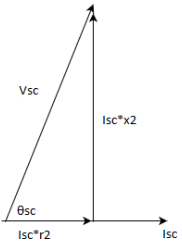
Determine the Impedance: The impedance ZZZ of the transformer can be calculated using the given percentage values for resistance and reactance:Z=R+jXZ = R + jXZ=R+jXwhere RRR and XXX are the resistance and reactance.Given:R=2% of Z (assuming Z as base impedance, Z = 100)R = 2\% \text{ of } Z \text{ (assuming Z as base impedance, Z = 100)}R=2% of Z (assuming Z as base impedance, Z = 100) X=2% of Z (assuming Z as base impedance, Z = 100)X = 2\% \text{ of } Z \text{ (assuming Z as base impedance, Z = 100)}X=2% of Z (assuming Z as base impedance, Z = 100)
-
Calculate the Impedance Angle: The impedance angle θ\thetaθ is determined by:θ=tan−1(XR)\theta = \tan^{-1} \left(\frac{X}{R}\right)θ=tan−1(RX)Substituting R=2R = 2R=2 and X=2X = 2X=2:θ=tan−1(22)=tan−1(1)=45°\theta = \tan^{-1} \left(\frac{2}{2}\right) = \tan^{-1}(1) = 45°θ=tan−1(22)=tan−1(1)=45°
Angle of the Short-Circuit Current:
The angle of the short-circuit current is equal to the angle of the impedance because the current in a short-circuit condition is essentially the same as the impedance angle.
Conclusion:
The steady short-circuit current draws at an angle of:
1. 45°

Which if the conditions is must be fulfilled for a satisfactory parallel operation of transformers?- a)Same voltage ratio
- b)Leakage impedances should be inversely proportional to kVA of the transformer
- c)Same pu impedance
- d)Correct polarity
Correct answer is option 'D'. Can you explain this answer?
Which if the conditions is must be fulfilled for a satisfactory parallel operation of transformers?
a)
Same voltage ratio
b)
Leakage impedances should be inversely proportional to kVA of the transformer
c)
Same pu impedance
d)
Correct polarity
|
|
Om Saini answered |
out of all, polarity must be correct for the connected transformers.
A. Positive sequence components – 5th harmonic component
B. Negative sequence components – 7th harmonic component
C. Zero sequence components – 3rd harmonic component
Above are the matching made for the harmonics and the associated harmonic component, then the correct marking is- a)A,B,C
- b)C
- c)A,B
- d)B,C
Correct answer is option 'B'. Can you explain this answer?
A. Positive sequence components – 5th harmonic component
B. Negative sequence components – 7th harmonic component
C. Zero sequence components – 3rd harmonic component
Above are the matching made for the harmonics and the associated harmonic component, then the correct marking is
B. Negative sequence components – 7th harmonic component
C. Zero sequence components – 3rd harmonic component
Above are the matching made for the harmonics and the associated harmonic component, then the correct marking is
a)
A,B,C
b)
C
c)
A,B
d)
B,C
|
|
Sanya Agarwal answered |
3m-1 phases are displaced 120° in opposite and (3m+1) in the same direction as the fundamental. Here ‘m’ is even integer. So 5th harmonic is in negative sequence and 7th harmonic component in positive sequence.
While conducting open circuit test and short circuit test on a transformer, status of low-voltage and high-voltage windings will be such that in
- a)OC test – l.v. open, SC test-h.v. short-circuited
- b)OC test – h.v. open, SC test-l.v. short-circuited
- c)OC test – l.v. open, SC test-l.v. short-circuited
- d)OC test – h.v. open, SC test-h.v. short-circuited
Correct answer is option 'A'. Can you explain this answer?
While conducting open circuit test and short circuit test on a transformer, status of low-voltage and high-voltage windings will be such that in
a)
OC test – l.v. open, SC test-h.v. short-circuited
b)
OC test – h.v. open, SC test-l.v. short-circuited
c)
OC test – l.v. open, SC test-l.v. short-circuited
d)
OC test – h.v. open, SC test-h.v. short-circuited
|
|
Harshitha Pillai answered |
For transformer testing:
-
Open Circuit (OC) Test:
- This test is used to determine the core losses and no-load characteristics of the transformer. In this test, the high-voltage (HV) winding is energized, and the low-voltage (LV) winding is kept open.
-
Short Circuit (SC) Test:
- This test is used to measure the copper losses and the impedance of the transformer. In this test, the low-voltage (LV) winding is short-circuited, and the high-voltage (HV) winding is energized.
So, the correct configuration is:
2. OC test – l.v. open, SC test – h.v. short-circuited
The efficiency of two identical transformers under load conditions can be determined by
- a)Short-circuit test
- b)Back-to-back test
- c)Open circuit test
- d)Any of the above
Correct answer is option 'B'. Can you explain this answer?
The efficiency of two identical transformers under load conditions can be determined by
a)
Short-circuit test
b)
Back-to-back test
c)
Open circuit test
d)
Any of the above
|
|
Ritika Sarkar answered |
Voltage regulation is the change in secondary voltage with secondary rated voltage.
Two single phase transformers A and B are operating in parallel having same impedance. But the x/r ratio of them are not equal. Then total kVA output of the output will be- a)less than sum of kVA of A and B
- b)more than sum of kVA of A and B
- c)equal to sum of kVA of A and B
- d)any of the mentioned
Correct answer is option 'A'. Can you explain this answer?
Two single phase transformers A and B are operating in parallel having same impedance. But the x/r ratio of them are not equal. Then total kVA output of the output will be
a)
less than sum of kVA of A and B
b)
more than sum of kVA of A and B
c)
equal to sum of kVA of A and B
d)
any of the mentioned
|
|
Vaibhav Mukherjee answered |
As the leakage reactances are not same for both the transformers, then Ia < I2 and Ib < I/2.
So the kVA will also be less than sum of individual A and B.
So the kVA will also be less than sum of individual A and B.
While conducting testing on the single phase transformer, one of the student tries to measure the resistance by putting an ammeter across one terminal of primary and other to secondary, the reading obtained will be- a)infinite
- b)zero
- c)finite
- d)negative finite
Correct answer is option 'A'. Can you explain this answer?
While conducting testing on the single phase transformer, one of the student tries to measure the resistance by putting an ammeter across one terminal of primary and other to secondary, the reading obtained will be
a)
infinite
b)
zero
c)
finite
d)
negative finite

|
Sagarika Patel answered |
As the primary and secondary are physically isolated, the impedance will be infinite for not electrically connected circuit.
A 200/400 V single phase transformer has leakage impedance z= r+jx. Then we can expect magnitude of load pf of ____ at zero voltage regulation.
- a)x/r leading
- b)x/r lagging
- c)r/x leading
- d)r/x lagging
Correct answer is option 'A'. Can you explain this answer?
A 200/400 V single phase transformer has leakage impedance z= r+jx. Then we can expect magnitude of load pf of ____ at zero voltage regulation.
a)
x/r leading
b)
x/r lagging
c)
r/x leading
d)
r/x lagging
|
|
Sagarika Patel answered |
ZVR occurs at the leading pf of load at x/r.
Operating transformers in parallel gives the advantage of
- a)reliable loading
- b)increased capacity of power system
- c)reducing the capacity of substation
- d)all of the mentioned
Correct answer is option 'D'. Can you explain this answer?
Operating transformers in parallel gives the advantage of
a)
reliable loading
b)
increased capacity of power system
c)
reducing the capacity of substation
d)
all of the mentioned

|
Rahul Chatterjee answered |
All are advantages of having parallel connection of transformers.
While estimating voltage regulation of a transformer, keeping- a)primary voltage constant
- b)secondary voltage constant
- c)voltage changes constant at primary
- d)all of the mentioned
Correct answer is option 'A'. Can you explain this answer?
While estimating voltage regulation of a transformer, keeping
a)
primary voltage constant
b)
secondary voltage constant
c)
voltage changes constant at primary
d)
all of the mentioned

|
Swara Dasgupta answered |
V.R. is calculated keeping the primary constant because then the core flux will change and the change of secondary voltage can not be fixed.
Two single phase transformers A and B are operating in parallel having different impedance and identical x/r ratio. Also impedance of A is more than that of B,then- a)Za/Zb = Sb/Sa
- b)Za/Zb = Sa/Sb
- c)Za/Zb = 1
- d)Za/Zb = (Sb/Sa)2
Correct answer is option 'A'. Can you explain this answer?
Two single phase transformers A and B are operating in parallel having different impedance and identical x/r ratio. Also impedance of A is more than that of B,then
a)
Za/Zb = Sb/Sa
b)
Za/Zb = Sa/Sb
c)
Za/Zb = 1
d)
Za/Zb = (Sb/Sa)2
|
|
Hridoy Chakraborty answered |
Leakage impedance in ‘ohms’ are inverse ratio of their respective kVA ratings.
If the pu impedance of a single phase transformer is 0.01+j0.05, then its regulation at p.f. of 0.8 lagging will be- a)3.8%
- b)2.2%
- c)-3.8%
- d)-2.2%
Correct answer is option 'A'. Can you explain this answer?
If the pu impedance of a single phase transformer is 0.01+j0.05, then its regulation at p.f. of 0.8 lagging will be
a)
3.8%
b)
2.2%
c)
-3.8%
d)
-2.2%
|
|
Divya Nair answered |
V.R. = (r(pu)*cosθ+x(pu)*sinθ)*100 % = (0.01*0.8 + 0.05*0.6)*100 = 3.8%
A 2000/1000/500 three winding transformer is to be used as auto transformer with supply of 3000 V. Two loads of 1050 kVA at 3500V,and other one at 180 kVA at 1000V. The total kVA supplied will be- a)1230 kVA
- b)1440 kVA
- c)1680 kVA
- d)1150 kVA
Correct answer is option 'A'. Can you explain this answer?
A 2000/1000/500 three winding transformer is to be used as auto transformer with supply of 3000 V. Two loads of 1050 kVA at 3500V,and other one at 180 kVA at 1000V. The total kVA supplied will be
a)
1230 kVA
b)
1440 kVA
c)
1680 kVA
d)
1150 kVA

|
Bijoy Kapoor answered |
Total kVA = 1050+180 = 1230 kVA.

If the per unit leakage impedance for the primary of a transformer is ‘x’ on the given rated base value. If the voltage and volt-amperes are doubled, then the changed per unit impedance will be- a)0.5x
- b)2x
- c)4x
- d)x
Correct answer is option 'A'. Can you explain this answer?
If the per unit leakage impedance for the primary of a transformer is ‘x’ on the given rated base value. If the voltage and volt-amperes are doubled, then the changed per unit impedance will be
a)
0.5x
b)
2x
c)
4x
d)
x
|
|
Swara Dasgupta answered |
pu(new base)=(x)*(MVA(new)/MVA(old))*(kV(old)/kV(new))^2
=x*2*(1/4)
=0.5x.
In a transformer, the load current is kept constant, while the power factor is varied. Under this situation, zero voltage regulation will be observed- a)independent of load power factor
- b)load power factor is leading
- c)load power factor is lagging
- d)at power factor equal to unity
Correct answer is option 'B'. Can you explain this answer?
In a transformer, the load current is kept constant, while the power factor is varied. Under this situation, zero voltage regulation will be observed
a)
independent of load power factor
b)
load power factor is leading
c)
load power factor is lagging
d)
at power factor equal to unity

|
Engineers Adda answered |
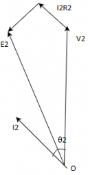
Voltage regulation is the change in secondary terminal voltage from no load to full load at a specific power factor of load and the change is expressed in percentage.
E2 = no-load secondary voltage
V2 = full load secondary voltage
Voltage regulation for the transformer is given by the ratio of change in secondary terminal voltage from no load to full load to no load secondary voltage.
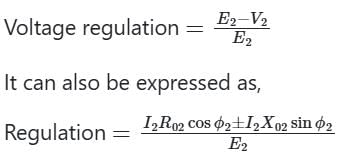
+ sign is used for lagging loads and
+ sign is used for lagging loads and
- ve sign is used for leading loads
Hence voltage regulation can be negative only for capacitive loads
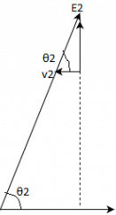
In transformer minimum voltage regulation occurs when the power factor of the load is leading.
The voltage regulation of the transformer is zero at a leading power factor load such as a capacitive load.
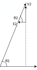
For zero voltage regulation, E2 = V2
> IR cos φ = IX sin φ (negative sign represents leading power factor loads)
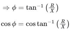
This is the leading power factor at which voltage regulation becomes zero while supplying the load.
This is the leading power factor at which voltage regulation becomes zero while supplying the load.
Two single phase transformers A and B are operating in parallel having same impedance. But the x/r ratio of them are not equal and xa > xb. Then- a)A has poorer pf than B
- b)B has poorer pf than B
- c)lesser power factor angle
- d)both operate at same power factor
Correct answer is option 'A'. Can you explain this answer?
Two single phase transformers A and B are operating in parallel having same impedance. But the x/r ratio of them are not equal and xa > xb. Then
a)
A has poorer pf than B
b)
B has poorer pf than B
c)
lesser power factor angle
d)
both operate at same power factor
|
|
Swati Tiwari answered |
It is not clear what you mean by "xa" in the question. If you provide more information, I can try to help you further.
Transformer operating in parallel will share a common load in the best possible manner if- a)leakage impedances are proportional to their kVA rating
- b)pu leakage impedances are equal
- c)leakage impedances are equal
- d)any of the mentioned
Correct answer is 'B'. Can you explain this answer?
Transformer operating in parallel will share a common load in the best possible manner if
a)
leakage impedances are proportional to their kVA rating
b)
pu leakage impedances are equal
c)
leakage impedances are equal
d)
any of the mentioned

|
Shivam Sharma answered |
For same pu leakage impedance, parallel operation of transformers become feasible.
Chapter doubts & questions for Single Phase Transformers - 6 Months Preparation for GATE Electrical 2025 is part of Electrical Engineering (EE) exam preparation. The chapters have been prepared according to the Electrical Engineering (EE) exam syllabus. The Chapter doubts & questions, notes, tests & MCQs are made for Electrical Engineering (EE) 2025 Exam. Find important definitions, questions, notes, meanings, examples, exercises, MCQs and online tests here.
Chapter doubts & questions of Single Phase Transformers - 6 Months Preparation for GATE Electrical in English & Hindi are available as part of Electrical Engineering (EE) exam.
Download more important topics, notes, lectures and mock test series for Electrical Engineering (EE) Exam by signing up for free.
6 Months Preparation for GATE Electrical
795 videos|1417 docs|800 tests
|
|
© EduRev
|
Education Revolution
|


|


Signup to see your scores
go up within 7 days!
Access 1000+ FREE Docs, Videos and Tests
Takes less than 10 seconds to signup