


All Exams >
Electrical Engineering (EE) >
6 Months Preparation for GATE Electrical >
All Questions
All questions of Mathematical Modelling of Systems for Electrical Engineering (EE) Exam


In liquid level systems, the units of capacitance of a tank is- a)m2
- b)m3
- c)

- d)m-2 s
Correct answer is option 'A'. Can you explain this answer?
In liquid level systems, the units of capacitance of a tank is
a)
m2
b)
m3
c)
d)
m-2 s
|
|
Rajesh Saha answered |
If q = flow; A = Area of cross-section and h = height of water in tank.
Then, ...(i)
Also, ...(ii)
On comparing equations.(i) and (ii), we have C (Farad) = A = m2
Then,
...(i)Also,
...(ii)On comparing equations.(i) and (ii), we have C (Farad) = A = m2
Which of the following is not a desirable property of a servomotor in feedback control systems?- a)Response should be fast.
- b)Torque-speed characteristic should be linear.
- c)It should be reversible.
- d)Relation between electrical control system and rotor speed should be non-linear.
Correct answer is option 'D'. Can you explain this answer?
Which of the following is not a desirable property of a servomotor in feedback control systems?
a)
Response should be fast.
b)
Torque-speed characteristic should be linear.
c)
It should be reversible.
d)
Relation between electrical control system and rotor speed should be non-linear.
|
|
Jaya Pillai answered |
Relation between electrical control system and rotor speed should be linear.
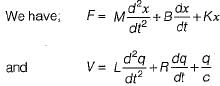
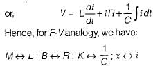
Assertion (A): D’Alembert’s principle states that “for any- body, the algebraic sum of externally applied forces and the forces resisting motion in any given direction is zero.
”Reason (R): D’Alembert principle is used in writing the equation of motion of mechanical systems.- a)Both A and R are true and R is a correct explanation of A.
- b)Both A and R are true but R is not a correct explanation of A.
- c)A is true but R is false.
- d)A is false but R is true.
Correct answer is option 'B'. Can you explain this answer?
Assertion (A): D’Alembert’s principle states that “for any- body, the algebraic sum of externally applied forces and the forces resisting motion in any given direction is zero.
”Reason (R): D’Alembert principle is used in writing the equation of motion of mechanical systems.
”Reason (R): D’Alembert principle is used in writing the equation of motion of mechanical systems.
a)
Both A and R are true and R is a correct explanation of A.
b)
Both A and R are true but R is not a correct explanation of A.
c)
A is true but R is false.
d)
A is false but R is true.
|
|
Vaibhav Mukherjee answered |
Both assertion and reason are true. However, the correct reason is that ali the forces in the direction of reference direction are considered as positive and the forces opposite to the reference direction are taken as negative due to which the algebraic sum of forces is zero.
Assertion (A): Stepper motors can be used for speed control.
Reason (R): The motor speed is proportional to the rate of command pulses.- a)Both A and R are true and R is a correct explanation of A.
- b)Both A and R are true but R is not a correct explanation of A.
- c)A is true but R is false.
- d)A is false but R is true.
Correct answer is option 'A'. Can you explain this answer?
Assertion (A): Stepper motors can be used for speed control.
Reason (R): The motor speed is proportional to the rate of command pulses.
Reason (R): The motor speed is proportional to the rate of command pulses.
a)
Both A and R are true and R is a correct explanation of A.
b)
Both A and R are true but R is not a correct explanation of A.
c)
A is true but R is false.
d)
A is false but R is true.
|
|
Avik Saha answered |
Stepper motors can be used for speed control because the motor speed is proportional to the rate of command pulses.
Assertion (A): An a.c. servomotor used in control system applications must have high starting torque and low inertia.
Reason (R): A large value of rotor diameter and small axial length gives a higher value of starting torque and a low value of inertia.- a)Both A and R are true and R is a correct explanation of A.
- b)Both A and R are true but R is not a correct explanation of A.
- c)A is true but R is false.
- d)A is false but R is true.
Correct answer is option 'C'. Can you explain this answer?
Assertion (A): An a.c. servomotor used in control system applications must have high starting torque and low inertia.
Reason (R): A large value of rotor diameter and small axial length gives a higher value of starting torque and a low value of inertia.
Reason (R): A large value of rotor diameter and small axial length gives a higher value of starting torque and a low value of inertia.
a)
Both A and R are true and R is a correct explanation of A.
b)
Both A and R are true but R is not a correct explanation of A.
c)
A is true but R is false.
d)
A is false but R is true.
|
|
Ashwin Mukherjee answered |
Reason is a false statement because small diameter and large axial length will give a lower value of inertia of motor.
Consider the following statements related to A.C. servomotors compared to D.C. servomotor used in control system applications.
1. It has less efficiency.
2. It is maintenance free.
3. It gives smooth operation.
4. It gives high power output.Which of these statements is/are true regarding an A.C. servomotor?- a)1,3, and 4
- b)4 only
- c)1,2 and 3
- d)2, 3 and 4
Correct answer is option 'C'. Can you explain this answer?
Consider the following statements related to A.C. servomotors compared to D.C. servomotor used in control system applications.
1. It has less efficiency.
2. It is maintenance free.
3. It gives smooth operation.
4. It gives high power output.
1. It has less efficiency.
2. It is maintenance free.
3. It gives smooth operation.
4. It gives high power output.
Which of these statements is/are true regarding an A.C. servomotor?
a)
1,3, and 4
b)
4 only
c)
1,2 and 3
d)
2, 3 and 4
|
|
Arindam Rane answered |
An A.C. servomotor doesn’t require brushes compared to a D.C. servomotor. So, it gives maintenance free operation. It’s efficiency is less due to low power output but, gives smooth operation.
The electrical time-constant of an armature- controlled dc servomotor is- a)larger than mechanical time-constant
- b)not related to mechanical time-constant
- c)equal to mechanical time-constant
- d)smaller than mechanical time-constant
Correct answer is option 'D'. Can you explain this answer?
The electrical time-constant of an armature- controlled dc servomotor is
a)
larger than mechanical time-constant
b)
not related to mechanical time-constant
c)
equal to mechanical time-constant
d)
smaller than mechanical time-constant
|
|
Dipanjan Nambiar answered |
Explanation:
Armature-controlled DC servomotors are widely used in various applications such as robotics, automation, and control systems. The electrical time constant of a DC servomotor is an important parameter that determines the response time of the motor to a change in the input signal. The electrical time constant of a motor is defined as the time required for the motor to reach 63.2% of its steady-state speed when subjected to a step change in the input voltage.
The mechanical time constant of a motor is the time required for the motor to reach 63.2% of its steady-state torque when subjected to a step change in the load torque. The mechanical time constant is related to the moment of inertia of the rotor and the load attached to the motor shaft.
The relationship between the electrical and mechanical time constants can be derived from the transfer function of the motor. The transfer function of a DC servomotor is given by:
G(s) = K / (s(Tm*Te) + 1)
where G(s) is the transfer function, K is the motor gain, Tm is the mechanical time constant, and Te is the electrical time constant.
From the transfer function, it can be seen that the electrical time constant is inversely proportional to the product of the mechanical time constant and the electrical time constant. Therefore, the electrical time constant is smaller than the mechanical time constant.
Hence, the correct answer is option D, i.e., the electrical time constant of an armature-controlled DC servomotor is smaller than the mechanical time constant.
Assertion (A): When the rotor of the synchro is inclined along any one of the stator axis completely, then this position is called electrical zero position.
Reason (R): When the rotor of the synchro is inclined along any one of the stator axis completely, then maximum voltage will be induced in that winding and almost zero voltage will be induced in the other two windings.- a)Both A and R are true and R is a correct explanation of A.
- b)Both A and R are true but R is not a correct explanation of A.
- c)A is true but R is false.
- d)A is false but R is true.
Correct answer is option 'A'. Can you explain this answer?
Assertion (A): When the rotor of the synchro is inclined along any one of the stator axis completely, then this position is called electrical zero position.
Reason (R): When the rotor of the synchro is inclined along any one of the stator axis completely, then maximum voltage will be induced in that winding and almost zero voltage will be induced in the other two windings.
Reason (R): When the rotor of the synchro is inclined along any one of the stator axis completely, then maximum voltage will be induced in that winding and almost zero voltage will be induced in the other two windings.
a)
Both A and R are true and R is a correct explanation of A.
b)
Both A and R are true but R is not a correct explanation of A.
c)
A is true but R is false.
d)
A is false but R is true.
|
|
Jayant Chopra answered |
Understanding the Assertion and Reason
The assertion (A) and reason (R) provided relate to the operation of a synchro, a device used in various applications for angular position measurement and control.
Assertion (A) Explained
- The assertion states that when the rotor of the synchro is aligned with one of the stator axes, it reaches an "electrical zero position."
- This position indicates that the rotor is optimally aligned with the stator, which is crucial for accurate measurements.
Reason (R) Explained
- The reason elaborates that at this position, the maximum voltage is induced in the aligned winding while minimal voltage is induced in the other two windings.
- This phenomenon occurs due to the principles of electromagnetic induction and the relationship between the rotor's position and the stator windings.
Relationship Between A and R
- Both A and R are true. The rotor's alignment indeed corresponds to the electrical zero position, where maximum voltage is induced in one winding.
- The explanation provided by R correctly supports the assertion A, as it clarifies why the electrical zero position is significant in the context of voltage induction.
Conclusion
- The correct answer is option 'A': Both A and R are true, and R is a correct explanation of A.
- Understanding this relationship is essential for applications in control systems and instrumentation within Electronics and Communication Engineering.
A synchro transmitter-receiver unit is a- a)two phase ac device
- b)3-phase ac device
- c)dc device
- d)single phase ac device
Correct answer is option 'D'. Can you explain this answer?
A synchro transmitter-receiver unit is a
a)
two phase ac device
b)
3-phase ac device
c)
dc device
d)
single phase ac device
|
|
Gautam Rao answered |
Understanding Synchro Transmitter-Receiver Units
A synchro transmitter-receiver unit is primarily used in control systems, allowing for the transmission of angular information between different locations. Understanding the type of device is crucial for applications in electronics and communication engineering.
What is a Synchro Device?
- Synchros are electromechanical devices that convert angular position into an electrical signal and vice versa.
- They are commonly used in applications such as aircraft instrumentation and radar systems.
Why is it a Single Phase AC Device?
- Synchros operate on the principle of electromagnetic induction, which requires alternating current (AC) for effective operation.
- The correct answer is option 'D' because:
- Single Phase AC Operation:
- Synchros typically use a single-phase AC supply for their operations, which allows them to function effectively in transmitting angular positions.
- Two-Phase vs. Three-Phase:
- While some devices may use two-phase or three-phase systems, synchros are designed to work efficiently with single-phase AC.
- DC Devices:
- Synchros cannot operate on direct current (DC) because they depend on the changing magnetic fields created by alternating current.
Applications in Engineering
- Synchro devices are utilized for feedback in control systems, enabling precise positioning and control in various applications.
- Their design specifications make them suitable for environments where reliability and accuracy are critical.
In summary, the synchro transmitter-receiver unit is classified as a single-phase AC device due to its operational reliance on alternating current for effective performance in angular position transmission.
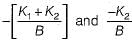
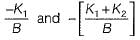
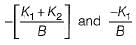
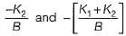
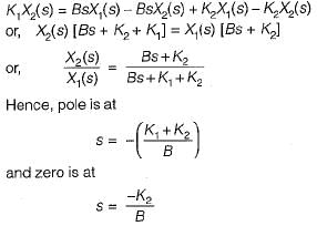
The poles-and zeros of the transfer function  for the mechanical system shown below are respectively
- a)
- b)
- c)
- d)
Correct answer is option 'A'. Can you explain this answer?
The poles-and zeros of the transfer function for the mechanical system shown below are respectively
for the mechanical system shown below are respectivelya)
b)
c)
d)
|
|
Tanishq Chavan answered |
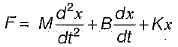
The differential equation for the given mechanical system is
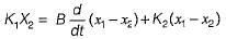
Taking Laplace transform on both sides, we get
Taking Laplace transform on both sides, we get
Assertion (A): When two time constant elements are cascaded interactively, the overall transfer function of such an arrangement is the product of two individual transfer functions.
Reason (R): There is loading effect present in such an arrangement.- a)Both A and R are true and R is a correct explanation of A.
- b)Both A and R are true but R is not a correct explanation of A.
- c)A is true but R is false.
- d)A is false but R is true.
Correct answer is option 'D'. Can you explain this answer?
Assertion (A): When two time constant elements are cascaded interactively, the overall transfer function of such an arrangement is the product of two individual transfer functions.
Reason (R): There is loading effect present in such an arrangement.
Reason (R): There is loading effect present in such an arrangement.
a)
Both A and R are true and R is a correct explanation of A.
b)
Both A and R are true but R is not a correct explanation of A.
c)
A is true but R is false.
d)
A is false but R is true.
|
|
Raj Singh answered |
When two time constant elements are cascaded non-interactively, then the overall transfer function is the product of two individual TFs.
Hence, assertion is false.
Hence, assertion is false.
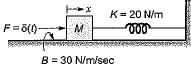
A mass spring system under equilibrium condition is shown in figure below.
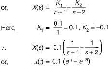
The output displacement x(t) for M = 10 kg is given by- a)e-t - e-2t
- b)10 (e-t - e-2t)
- c)0.1 (e-t -e-2t)
- d)5 (e-t + e-2t)
Correct answer is option 'C'. Can you explain this answer?
A mass spring system under equilibrium condition is shown in figure below.
The output displacement x(t) for M = 10 kg is given by
The output displacement x(t) for M = 10 kg is given by
a)
e-t - e-2t
b)
10 (e-t - e-2t)
c)
0.1 (e-t -e-2t)
d)
5 (e-t + e-2t)
|
|
Ipsita Gupta answered |
The differential equation for the given system is
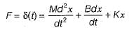
or,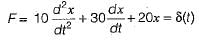
Taking Laplace transform on both sides, we get: (10s2 + 30s + 20) X(s) = 1
or,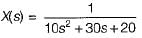
or,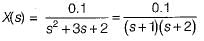
or,
Taking Laplace transform on both sides, we get: (10s2 + 30s + 20) X(s) = 1
or,
or,
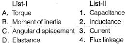
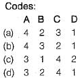
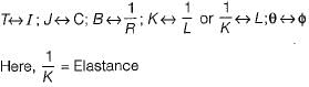
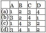
Match List-I with List-II and select the correct answer using the codes given below the lists:
- a)a
- b)b
- c)c
- d)d
Correct answer is option 'C'. Can you explain this answer?
Match List-I with List-II and select the correct answer using the codes given below the lists:
a)
a
b)
b
c)
c
d)
d
|
|
Yashvi Saha answered |
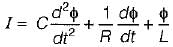
For mechanical rotational system, we have:

For electrical system, we have
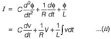
Comparing equations (i) and (ii), we have:
For electrical system, we have
Comparing equations (i) and (ii), we have:
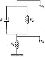
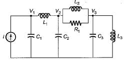
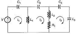
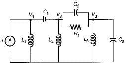
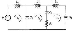
Consider the mechanical system shown in figure below.
Which one of the following circuits shows the force-voltage analogous electrical circuit for the mechanical diagram shown above?- a)
- b)
- c)
- d)
Correct answer is option 'D'. Can you explain this answer?
Consider the mechanical system shown in figure below.
Which one of the following circuits shows the force-voltage analogous electrical circuit for the mechanical diagram shown above?
Which one of the following circuits shows the force-voltage analogous electrical circuit for the mechanical diagram shown above?
a)
b)
c)
d)
|
|
Anjali Datta answered |
Thus, option (d) will be the correct circuit.
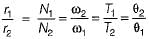
Two wheels are mechanically coupled as shown in figure below.
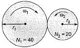
Here, ω1 and ω2 = angular velocities (in rad/s)
T1 and T2 = Torque (in N-m)
r1 and r2 = radius of the wheels (in cm)
θ1 and θ2 = angular displacements (in degrees)
N1, and N2 = No. of teeths on wheels
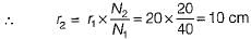
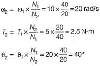
It is given that ω1 = 10 rad/s, N1 = 40, N2 - 20,
T1 = 5 N-m, r1 = 20 cm and θ1 = 20°.
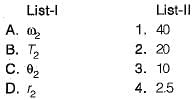
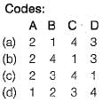
Match List-I with List-ll and select the correct answer using the codes given below the lists:
- a)a
- b)b
- c)c
- d)d
Correct answer is option 'B'. Can you explain this answer?
Two wheels are mechanically coupled as shown in figure below.
Here, ω1 and ω2 = angular velocities (in rad/s)
T1 and T2 = Torque (in N-m)
r1 and r2 = radius of the wheels (in cm)
θ1 and θ2 = angular displacements (in degrees)
N1, and N2 = No. of teeths on wheels
It is given that ω1 = 10 rad/s, N1 = 40, N2 - 20,
T1 = 5 N-m, r1 = 20 cm and θ1 = 20°.
Match List-I with List-ll and select the correct answer using the codes given below the lists:
a)
a
b)
b
c)
c
d)
d
|
|
Kirti Sen answered |
We know that,
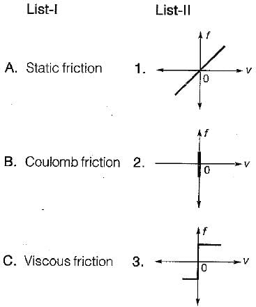
Match List - I (Types of friction) with List - II (Corresponding frictional force vs Velocity curve) and select the correct answer using the codes given below the lists:
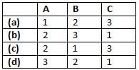
- a)d
- b)b
- c)c
- d)a
Correct answer is option 'A'. Can you explain this answer?
Match List - I (Types of friction) with List - II (Corresponding frictional force vs Velocity curve) and select the correct answer using the codes given below the lists:
a)
d
b)
b
c)
c
d)
a

|
Imtiaz Ahmad answered |
let's analyze the characteristics of each type of friction:
- Static friction (A) - This type of friction occurs when there is no relative motion between the surfaces in contact. The frictional force increases up to a maximum value as the applied force increases, and it equals the applied force until motion starts. After this point, it transitions to kinetic friction. This corresponds to a frictional force that stays at zero until the velocity starts changing.
- Coulomb friction (B) - Also known as kinetic or dry friction, this type of friction remains constant regardless of the velocity once the object is in motion. It is independent of the velocity of the moving surfaces. This corresponds to a horizontal line for the frictional force versus velocity curve.
- Viscous friction (C) - This type of friction is proportional to the velocity. The frictional force increases linearly with the velocity. This corresponds to a linear relationship between frictional force and velocity.
Now, match these characteristics with the curves in List-II:
- Curve 1 shows a frictional force that increases linearly with velocity. This corresponds to Viscous friction.
- Curve 2 shows a constant frictional force regardless of the velocity. This corresponds to Coulomb friction.
- Curve 3 shows a frictional force that is zero until a certain point (indicating no movement) and then jumps to a certain value once motion starts. This corresponds to Static friction.
So, the correct matching is:
- A: 3 (Static friction)
- B: 2 (Coulomb friction)
- C: 1 (Viscous friction)
The correct answer is (d): 3 2 1
The stator of the synchros is made of- a)laminated silicon steel
- b)cast iron
- c)stainless steel
- d)none of the above
Correct answer is option 'C'. Can you explain this answer?
The stator of the synchros is made of
a)
laminated silicon steel
b)
cast iron
c)
stainless steel
d)
none of the above
|
|
Avantika Kaur answered |
Introduction
The stator of synchros is a critical component in electrical engineering, particularly in applications requiring precise angular position sensing and control. Understanding the materials used in its construction is essential for optimizing performance.
Material Composition
- Stainless Steel: The correct answer is option 'C' because the stator is often made from stainless steel. This material offers several advantages:
- Corrosion Resistance: Stainless steel is highly resistant to corrosion, making it suitable for various environmental conditions.
- Durability: It provides excellent mechanical strength, ensuring longevity and reliability in operation.
Comparison with Other Materials
- Laminated Silicon Steel:
- Often used in transformers and electric motors for its magnetic properties.
- However, it is less suitable for synchros due to potential issues with corrosion and mechanical wear.
- Cast Iron:
- While it has good strength and is cost-effective, cast iron is heavy and brittle, making it less favorable for applications requiring precise movement and minimal weight.
Conclusion
In summary, the choice of stainless steel for the stator of synchros is driven by its unique combination of strength, resistance to environmental degradation, and overall suitability for precision applications in electrical engineering. This ensures optimal performance and reliability in various operational environments.
A field controlled DC servomotor is a- a)open loop system with a large time constant.
- b)closed loop system with a small time constant.
- c)open loop system with a small time constant.
- d)closed loop system with a large time constant.
Correct answer is option 'A'. Can you explain this answer?
A field controlled DC servomotor is a
a)
open loop system with a large time constant.
b)
closed loop system with a small time constant.
c)
open loop system with a small time constant.
d)
closed loop system with a large time constant.
|
|
Diya Kumar answered |
Explanation:
A field controlled DC servomotor is a type of motor that is used in control systems to perform precise movements. These motors are widely used in robotics, automation, and other applications where precise control is required. The motor works by controlling the magnetic field around the rotor and the stator. The magnetic field is controlled by a DC current that flows through the field winding.
Open Loop System:
An open-loop system is a type of control system where there is no feedback between the output and the input. In other words, the output is not fed back to the input to make adjustments. The system relies on the input signal to control the output. An open-loop system is simple and easy to implement, but it has some drawbacks. It does not take into account any disturbances or changes in the system, and it is less accurate than a closed-loop system.
Large Time Constant:
The time constant of a system is a measure of the system's response time. It is the time it takes for the response to reach 63.2% of its final value when subjected to a step change. A large time constant means that the system's response is slow. The system takes longer to reach its steady-state value, and it is less responsive to changes in the input.
Field Controlled DC Servomotor:
A field controlled DC servomotor is an open-loop system with a large time constant. The motor's response time is slow, and it is less responsive to changes in the input. The motor's magnetic field is controlled by a DC current that flows through the field winding. The output of the motor depends on the input signal and the magnetic field strength. The motor does not take into account any disturbances or changes in the system, and it is less accurate than a closed-loop system.
Conclusion:
In conclusion, a field controlled DC servomotor is an open-loop system with a large time constant. The motor's response time is slow, and it is less responsive to changes in the input. The motor's magnetic field is controlled by a DC current that flows through the field winding. The motor does not take into account any disturbances or changes in the system, and it is less accurate than a closed-loop system.
A synchro is used to- a)accelerate a rotating shaft.
- b)convert an angular position of shaft into an electrical signal
- c)convert linear motion into angular position
- d)amplify low frequency signals
Correct answer is option 'B'. Can you explain this answer?
A synchro is used to
a)
accelerate a rotating shaft.
b)
convert an angular position of shaft into an electrical signal
c)
convert linear motion into angular position
d)
amplify low frequency signals
|
|
Naveen Mukherjee answered |
Understanding Synchros
A synchro is an electromechanical device primarily used in control systems to transmit angular position information. It converts mechanical rotation into an electrical signal, making it crucial for various applications in electrical engineering.
Key Functionality of a Synchro
- Position Sensing: Synchros are designed to detect the angular position of a rotating shaft. When the shaft rotates, the synchro generates a corresponding electrical output.
- Electrical Signal Conversion: The primary function of a synchro is to convert angular position into an electrical signal. This output can be used in control systems to monitor and control the position of machinery or equipment.
Components of a Synchro
- Rotor: The rotating part that is connected to the shaft whose position is being measured.
- Stator: The stationary part that interacts with the rotor to produce an electrical output based on its position.
Applications of Synchros
- Control Systems: Used in various control applications, such as aircraft navigation and industrial automation.
- Feedback Mechanisms: Synchros provide feedback in systems requiring precise position control, enhancing overall system accuracy.
Conclusion
In summary, option 'B' is correct because a synchro's primary role is to convert the angular position of a shaft into an electrical signal, making it an essential component in numerous engineering applications. This functionality enables precise control and monitoring in various systems.
Match List - I (Control system components) with List - II (Principle of operation) and select the correct answer using the codes given below the lists:
List - I
A. Synchronous
B. Potentiometer
C. Tachometer
List - lI
1. Mechanical displacement into electrical energy.
2. Angular position of a shaft into an electrical signal.
3. Electrical output proportional to speed.
Codes:
- a)a
- b)b
- c)c
- d)d
Correct answer is option 'B'. Can you explain this answer?
Match List - I (Control system components) with List - II (Principle of operation) and select the correct answer using the codes given below the lists:
List - I
A. Synchronous
B. Potentiometer
C. Tachometer
List - lI
1. Mechanical displacement into electrical energy.
2. Angular position of a shaft into an electrical signal.
3. Electrical output proportional to speed.
Codes:
List - I
A. Synchronous
B. Potentiometer
C. Tachometer
List - lI
1. Mechanical displacement into electrical energy.
2. Angular position of a shaft into an electrical signal.
3. Electrical output proportional to speed.
Codes:
a)
a
b)
b
c)
c
d)
d

|
Ritu Kumari answered |
Ya correct answer is b


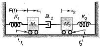
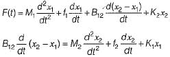
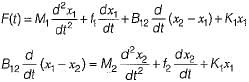
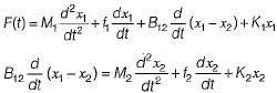
Consider the mechanical system shown below:
The system is described by the differential equations:- a)
- b)
- c)
- d)none of the above
Correct answer is option 'C'. Can you explain this answer?
Consider the mechanical system shown below:
The system is described by the differential equations:
The system is described by the differential equations:
a)
b)
c)
d)
none of the above
|
|
Maulik Chawla answered |
The free-body diagram for the two masses will be shown as below.
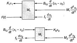
Hence, the differential equations for the two masses can be written as follows:
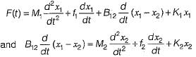
Hence, the differential equations for the two masses can be written as follows:
An a.c. servomotor- a)is noise free and has smaller R to X ratio.
- b)is noisy and has higher R to X ratio.
- c)is noise free and has larger R to X ratio,
- d)is noisy and has smaller R to X ratio.
Correct answer is option 'C'. Can you explain this answer?
An a.c. servomotor
a)
is noise free and has smaller R to X ratio.
b)
is noisy and has higher R to X ratio.
c)
is noise free and has larger R to X ratio,
d)
is noisy and has smaller R to X ratio.
|
|
Anirban Gupta answered |
Explanation:
AC Servomotor:
An AC servomotor is a type of motor that is commonly used in automation and control systems to achieve precise and accurate motion control.
Noise:
One of the key differences between different types of servomotors is the level of noise they produce during operation. AC servomotors are known for being noise-free compared to other types of motors such as DC servomotors.
R to X Ratio:
The R to X ratio of a motor refers to the ratio of its resistance (R) to its reactance (X). In the case of an AC servomotor, it typically has a larger R to X ratio compared to other types of motors.
Explanation of Answer:
In the given options, option 'c' states that an AC servomotor is noise-free and has a larger R to X ratio. This is the correct answer because AC servomotors are indeed known for their quiet operation and they typically have a larger R to X ratio, which contributes to their efficiency and performance in various applications.
Therefore, option 'c' accurately describes the characteristics of an AC servomotor, making it the correct choice in this scenario.
Chapter doubts & questions for Mathematical Modelling of Systems - 6 Months Preparation for GATE Electrical 2025 is part of Electrical Engineering (EE) exam preparation. The chapters have been prepared according to the Electrical Engineering (EE) exam syllabus. The Chapter doubts & questions, notes, tests & MCQs are made for Electrical Engineering (EE) 2025 Exam. Find important definitions, questions, notes, meanings, examples, exercises, MCQs and online tests here.
Chapter doubts & questions of Mathematical Modelling of Systems - 6 Months Preparation for GATE Electrical in English & Hindi are available as part of Electrical Engineering (EE) exam.
Download more important topics, notes, lectures and mock test series for Electrical Engineering (EE) Exam by signing up for free.
6 Months Preparation for GATE Electrical
675 videos|1297 docs|786 tests
|
|
© EduRev
|
Education Revolution
|


|


Signup on EduRev and stay on top of your study goals
10M+ students crushing their study goals daily