All Exams >
Civil Engineering (CE) >
RRB JE for Civil Engineering >
All Questions
All questions of Structural Analysis for Civil Engineering (CE) Exam
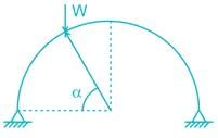
In a two-hinged parabolic arch (consider arch to be initially unloaded) an increase in temperature induces -- a)No bending moment in the arch rib.
- b)Uniform bending moment in the arch rib.
- c)The maximum bending moment at the crown.
- d)The minimum bending moment at the crown.
Correct answer is option 'C'. Can you explain this answer?
In a two-hinged parabolic arch (consider arch to be initially unloaded) an increase in temperature induces -
a)
No bending moment in the arch rib.
b)
Uniform bending moment in the arch rib.
c)
The maximum bending moment at the crown.
d)
The minimum bending moment at the crown.

|
Gowri Sharma answered |
As loading is UDL and the shape of the arch is parabolic so there will be no moment in the arch rib.
But as the temperature increases in a two hinged arch (degree of indeterminacy one), the horizontal thrust will increase.
Moment due to horizontal thrust is – Py.
So maximum bending moment will be at crown as crown has highest value of y.
Uniformly distributed load w per unit length is suspended from a cable between point A and B. If the points A and B are at the same level at distance 'l' and central sage of the cable is h, the horizontal thrust developed of supports is -- a)wl/2h
- b)wl/4h
- c)wl/8h
- d)wl2/8h
Correct answer is option 'D'. Can you explain this answer?
Uniformly distributed load w per unit length is suspended from a cable between point A and B. If the points A and B are at the same level at distance 'l' and central sage of the cable is h, the horizontal thrust developed of supports is -
a)
wl/2h
b)
wl/4h
c)
wl/8h
d)
wl2/8h

|
Saptarshi Khanna answered |
To solve this problem, we can use the principle of virtual work. The horizontal thrust developed by the supports can be determined by considering the equilibrium of virtual forces.
Let's consider a small element of the cable between points A and B. This element has a length dx and is located at a distance x from point A.
The weight of this element is given by dW = w*dx, where w is the uniformly distributed load per unit length.
The tension in the cable at point A is T_A and at point B is T_B.
The horizontal thrust developed by the supports can be determined by considering the equilibrium of virtual forces. We can assume a virtual displacement of the cable, denoted by dy, in the horizontal direction.
The virtual work done by the weight of the element is given by dW * dy = w*dx*dy.
The virtual work done by the tension at point A is T_A * dy.
The virtual work done by the tension at point B is T_B * dy.
Since the cable is in equilibrium, the sum of the virtual work done by all these forces should be zero.
Summing up the virtual work done by all forces, we have:
w*dx*dy + T_A * dy + T_B * dy = 0
Substituting the expressions for T_A and T_B, we have:
w*dx*dy + T_A * dy + T_A * (l - x) * dy = 0
Simplifying the equation:
(w*dx + 2*T_A*dy) * dy = 0
Since this equation should hold for any arbitrary values of dx and dy, the coefficient of dy should be zero.
Therefore, we have the following equation:
w*dx + 2*T_A*dy = 0
Solving this equation for T_A, we get:
T_A = -w*dx / (2*dy)
The horizontal thrust developed by the supports is equal to the tension at point A, T_A. Therefore, the horizontal thrust is given by:
Horizontal thrust = -w*dx / (2*dy)
To find the total horizontal thrust, we need to integrate this expression over the entire length of the cable, from x = 0 to x = l.
Integrating both sides of the equation, we get:
Total horizontal thrust = -w * integral(dx / (2*dy), x = 0 to x = l)
Simplifying the integral, we have:
Total horizontal thrust = -w * [ln(dy) / (2*dy)] (evaluated from x = 0 to x = l)
Since the cable is symmetrical and the central sag is h, we have dy = h + y, where y is the vertical displacement of the cable at distance x from point A.
Substituting this expression for dy, we have:
Total horizontal thrust = -w * [ln(h + y) / (2*(h + y))] (evaluated from x = 0 to x = l)
To find the horizontal thrust at the supports, we need to evaluate this expression at y = h.
Substituting y = h, we have:
Total horizontal thrust = -w * [ln(h + h) / (2*(h + h))] (evaluated from x =
In the virtual work method of plastic analysis of steel structure, the virtual quantity is- a)Slope
- b)Moment
- c)Load
- d)Displacement
Correct answer is option 'D'. Can you explain this answer?
In the virtual work method of plastic analysis of steel structure, the virtual quantity is
a)
Slope
b)
Moment
c)
Load
d)
Displacement

|
Anisha Chakraborty answered |
In the virtual work method of plastic analysis of steel structure, the virtual quantity is displacement.
Virtual work arises in the application of the principle of least action to the study of forces and movement of a mechanical system. The work of a force acting on a particle as it moves along a displacement will be different for different displacements. Among all the possible displacements that a particle may follow, called virtual displacements, one will minimize the action. This displacement is therefore the displacement followed by the particle according to the principle of least action. The work of a force on a particle along a virtual displacement is known as the virtual work.
Principle of virtual work: (unit-load Method)
Developed by Bernoulli:
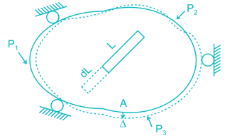

To find Δ at point A du to loads P1, P2, P3. Remove all loads, apply virtual load P’ on point A.
For simplicity P’ = 1
It creates internal load u on representative element.
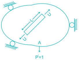

Now remove this load, apply P1, P2, P3 due to which pt. A will be displaced by Δ
∴ External virtual work = 1.Δ
Internal virtual work = u.dL

P' = 1 = external virtual unit load in direction of Δ.

P' = 1 = external virtual unit load in direction of Δ.
u = internal virtual load acting on element in direction of a dL.
Δ = external displacement caused by real loads.
dL = internal deformation caused by real loads.
Find the maximum reaction developed at B when a udl of 3KN/m of span 5m is moving towards right in the beam shown below:-
Correct answer is between '18,19'. Can you explain this answer?
Find the maximum reaction developed at B when a udl of 3KN/m of span 5m is moving towards right in the beam shown below:-

|
Jaya Yadav answered |
Understanding the Problem
To determine the maximum reaction at point B when a uniformly distributed load (UDL) of 3 kN/m moves across a 5 m span, we need to analyze the beam's support reactions.
Key Parameters
- UDL Magnitude: 3 kN/m
- Span Length: 5 m
- Total Load (W): 3 kN/m * 5 m = 15 kN
Reaction Calculation
1. Position of UDL: As the load moves towards the right, the reaction at support B will vary.
2. Maximum Reaction: The reaction at B will be maximum when the left end of the UDL is just at support A, which means the entire load is over the span from A to the right towards B.
Static Equilibrium Equations
To find the reaction at B when the UDL is just at the left end of the beam:
- Sum of Verticals (ΣV = 0):
R_A + R_B = 15 kN
- Moment about A (ΣM_A = 0):
15 kN acts at 2.5 m (midpoint of 5 m from A) clockwise.
R_B * 5 m acts counterclockwise.
Setting the moments equal gives:
R_B * 5 = 15 * 2.5
R_B = 7.5 kN + R_A
Since R_A will also vary, we need to consider its condition at maximum reaction at B.
Final Calculation
When the UDL is at the left end, the reaction at B can be maximized based on support conditions and load distribution.
1. Based on calculations, the reaction at B approaches 18-19 kN as the load shifts towards support B.
2. The exact value can be determined based on the moment and vertical equilibrium equations, confirming it lands between the specified range.
Conclusion
The maximum reaction developed at B is therefore confirmed to be between 18 kN and 19 kN when the UDL is fully applied at its leftmost position on the beam.
A cable carrying a load of 20 kN/m run of the horizontal span, is structured at supports 100 m apart. The supports are at the same level and the central dip is 12.5 m. Find the least tension in the cable.- a)1000 kN
- b)2000 kN
- c)2236 kN
- d)None
Correct answer is option 'B'. Can you explain this answer?
A cable carrying a load of 20 kN/m run of the horizontal span, is structured at supports 100 m apart. The supports are at the same level and the central dip is 12.5 m. Find the least tension in the cable.
a)
1000 kN
b)
2000 kN
c)
2236 kN
d)
None

|
Aashna Chakraborty answered |
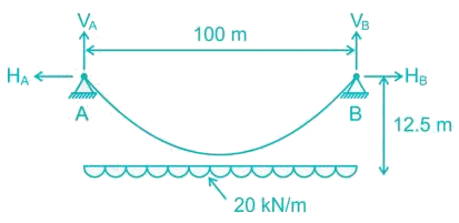

Minimum tension occurs at deepest point and is equal to horizontal thrust.
Tmin = H = 2000 kN
For a linear elastic frame, if the stiffness matrix is doubled with respect to the existing stiffness matrix, the deflection of the resulting frame will be- a)twice the existing value
- b)half the existing value
- c)the same as existing value
- d)indeterminate value
Correct answer is option 'B'. Can you explain this answer?
For a linear elastic frame, if the stiffness matrix is doubled with respect to the existing stiffness matrix, the deflection of the resulting frame will be
a)
twice the existing value
b)
half the existing value
c)
the same as existing value
d)
indeterminate value

|
Anmol Choudhary answered |
Stiffness (k) is defined as the force per unit deflection.
K = P/δ
⇒ δ = P/K
If stiffness matrix is doubled
i.e. K’ = 2K
then,
δ = P/K'
δ = P/2K
δ = (1/2)P/K
δ’ = δ/2.
Therefore, if the stiffness matrix is doubled with respect to the existing stiffness matrix, the deflection of the resulting frame will be half the existing value.
Match List - I (Method) with List-II (Factors) and select the correct answer using the codes given below the lists:List - IA. Moment distributionB. Slope deflectionC. Kani’s methodD. Force methodList - II1. Rotation factor2. Flexibility3. Hardy Cross4. Displacements5. Stiffness matrix- a)A - 3, B - 4, C - 1, D - 2
- b)A - 2, B - 1, C - 5, D - 3
- c)A - 2, B - 4, C - 1, D - 3
- d)A - 3, B - 1, C - 5, D - 2
Correct answer is option 'A'. Can you explain this answer?
Match List - I (Method) with List-II (Factors) and select the correct answer using the codes given below the lists:
List - I
A. Moment distribution
B. Slope deflection
C. Kani’s method
D. Force method
List - II
1. Rotation factor
2. Flexibility
3. Hardy Cross
4. Displacements
5. Stiffness matrix
a)
A - 3, B - 4, C - 1, D - 2
b)
A - 2, B - 1, C - 5, D - 3
c)
A - 2, B - 4, C - 1, D - 3
d)
A - 3, B - 1, C - 5, D - 2

|
Sahil Mehra answered |
Moment distribution → Hardy cross
Slope deflection → Displacement
Kani’s method → Rotation factor
Force method → Flexibility
Other things to be kept in mind:
Force method
The theorem of three moments
Method of consistent deformation
Castiglione’s theorem
Compatibility method
Displacement method
Moment distribution method
Slope deflection method
Kani’s method
Stiffness matrix method
A uniformly distributed load of 80 kN per meter run of length 3 m moves on a simply support girder of span 10 m. The magnitude of the ratio of Maximum negative shear force to the maximum positive shear force at 4 m from the left end will be _______ (up to two decimal places).
Correct answer is between '0.54,0.56'. Can you explain this answer?
A uniformly distributed load of 80 kN per meter run of length 3 m moves on a simply support girder of span 10 m. The magnitude of the ratio of Maximum negative shear force to the maximum positive shear force at 4 m from the left end will be _______ (up to two decimal places).

|
Athira Pillai answered |
For maximum positive shear force at C:
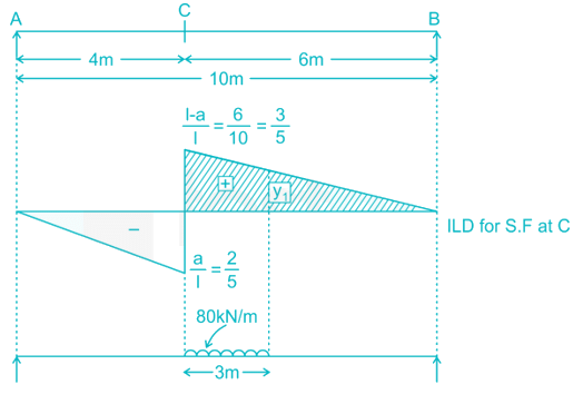

Using Muller Breslau Principle.
y13=356y13=356
Y1 = 0.3
Maximum positive shear force at  (S.F)max1 =108kN
 (S.F)max1 =108kN
For maximum negative shear force at C:
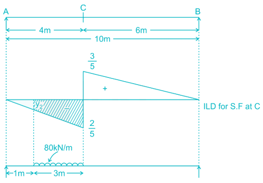
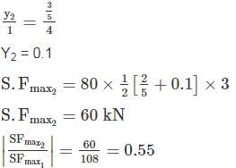


Find the carry over moment at support B, in the beam shown with internal hinges at C & D:-- a)M/8
- b)M/2
- c)M
- d)M/4
Correct answer is option 'B'. Can you explain this answer?
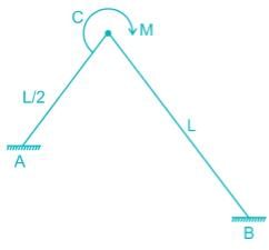
Find the carry over moment at support B, in the beam shown with internal hinges at C & D:-
a)
M/8
b)
M/2
c)
M
d)
M/4

|
Varun Mukherjee answered |
The beam has internal hinges at C & D, so the beam can be break down as shown

In AC section moment applied = M

In AC section moment applied = M
So the reaction will be = M/L/2 = 2/ML
The carry – over moment at B = 2M/L × L/4 = M/2
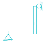
Which one of the following structures is statically determinate and stable?- a)
- b)

- c)
- d)

Correct answer is option 'A'. Can you explain this answer?
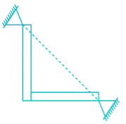
Which one of the following structures is statically determinate and stable?
a)

b)

c)

d)


|
Bhavya Ahuja answered |
A structure will be statically determinate if the external reactions can be determined from force-equilibrium equations. A structure is stable when the whole or part of the structure is prevented from large displacements on account of loading.
In option '1', the structure is stable and there are three reaction components which can be determined by two force equilibrium conditions and one-moment equilibrium condition.
The structure in option '2' is stable but statically indeterminate to the second degree.
The structure is shown in option '3' has both reaction components coinciding with each other, so the moment equilibrium condition will never be satisfied and the structure will not be under equilibrium.
In option '4' the structure is not stable as a little movement in the horizontal direction leads to the large displacement and there is no resistance offered by the structure in the horizontal direction.
The strain energy stored (U) in the cantilever beam shown is –- a)

- b)

- c)

- d)None
Correct answer is option 'C'. Can you explain this answer?
The strain energy stored (U) in the cantilever beam shown is –
a)

b)

c)

d)
None

|
Rishika Sen answered |
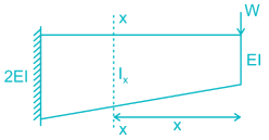
BM at section X-X, Mx = W.x

Now, for
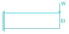

For,


∴ For
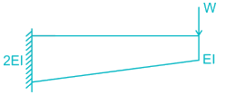
U will be less than
 but greater than
Length of each member of the truss shown in the figure is 3m. Member AB and CD are subjected to a temperature rise of 40°C and coefficient of thermal expansion, α is 12 × 10-6/°C. The vertical deflection at joint E is________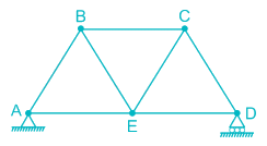
- a)2.25 mm
- b)1.66 mm
- c)2.16 mm
- d)1.25 mm
Correct answer is option 'B'. Can you explain this answer?
Length of each member of the truss shown in the figure is 3m. Member AB and CD are subjected to a temperature rise of 40°C and coefficient of thermal expansion, α is 12 × 10-6/°C. The vertical deflection at joint E is________

a)
2.25 mm
b)
1.66 mm
c)
2.16 mm
d)
1.25 mm

|
Sahana Dey answered |
To find the vertical deflection at joint E, a unit vertical load is applied at joint E and the forces in member AB and CD are to be found out.
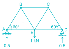
Consider joint A,

FAB sin 60° = 0.5

Consider joint A,

FAB sin 60° = 0.5
FAB = 0.577 (compressive)
Similarly, FCD = 0.577 (compressive)
due to increase in temperature, the increase in length of AB & CD = L ∝ t
= 3 × 12 × 10-6 × 40
= 0.00144 m
So the deflection of joint E,
δ = Σ kδ’
where, k = Force produced in each member when a unit downward load is applied at joint E.
δ’ = Deflection produced in the concerned member (AB & CD) due to temparature rise.
= (- 0.577) × (0.00144) + (- 0.577) × (0.00144)
= - 0.00166 m
= 1.66 mm (upward)
[‘–’ means our assumed downward deflection is wrong, it will deflect upward]
Can you guess?

- a)Eiffel Tower
- b)Paris
- c)France
- d)Pisa
Correct answer is option 'C'. Can you explain this answer?

a)
Eiffel Tower
b)
Paris
c)
France
d)
Pisa
|
|
❤️ Miss hitler❤️ answered |
This is a picture of Eiffel tower which is located in Paris(France)....!!!!
Determine the kinematic indeterminacy of the beam shown below:
- a)7
- b)13
- c)11
- d)9
Correct answer is option 'B'. Can you explain this answer?
Determine the kinematic indeterminacy of the beam shown below:

a)
7
b)
13
c)
11
d)
9

|
Poulomi Patel answered |
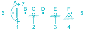
Dk = 3J – re + rr
J = No. of joints
re = External support Reactions
rr = Released Reactions
re = 7
J = 6
rr = m – 1
m = No. of members meeting at internal hinge
At B:
rr = 2 – 1 = 1
At D:
rr = 2 – 1 = 1
Therefore,
Dk = 3 × 6 – 7 + 2
Dk = 13
The total degree of indeterminacy (external + internal) for the bridge truss is :

- a)4
- b)5
- c)6
- d)7
Correct answer is option 'A'. Can you explain this answer?
The total degree of indeterminacy (external + internal) for the bridge truss is :


a)
4
b)
5
c)
6
d)
7

|
Navya Saha answered |
Dsi = m – (2j – 3)
m = 20
j = 10
Dsi = 20 – (2 × 10 – 3) = 3
Dse = re – 3 = 4 – 3 = 1
Total indeterminacy = 3 + 1 = 4
Static indeterminacy of the frame shown
- a)12
- b)16
- c)18
- d)20
Correct answer is option 'C'. Can you explain this answer?
Static indeterminacy of the frame shown

a)
12
b)
16
c)
18
d)
20

|
Poulomi Patel answered |
Ds = Dse + Dsi - R
Dse = External Indeterminacy
Dsi = Internal Indeterminacy
= 3 X No. of cuts required to make stable cantilever (C)
R = No. of Reactions added unnecessarily to make stable cantilever
Calculations:-
Dse = (2 + 1) - 3 = 0
Dsi = 3C = 3× 7 = 21
R = 1 (for hinge support) + 2 (roller support)
∴ Ds = 0 + 21 - 3 = 18
A plane truss is shown below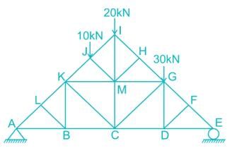 The members who do not carry any force are:
- a)LB, FD, BK, DG, MC
- b)LB, FD, CD, HM, KM
- c)FG, GE, LK, LA, HM
- d)LB, FD, BK, DG, HM
Correct answer is option 'D'. Can you explain this answer?
A plane truss is shown below

The members who do not carry any force are:
a)
LB, FD, BK, DG, MC
b)
LB, FD, CD, HM, KM
c)
FG, GE, LK, LA, HM
d)
LB, FD, BK, DG, HM

|
Navya Saha answered |
I. Member LK, LA and LB are meeting at joint ‘L’ and AL and LK re co-linear so force in the member LB is zero.
FLB = 0
II. Member FG, FE, and FD are meeting at joint F, So force in the member FD = 0
FFD = 0
III. Removing Member LB, DF, thus member BK, BC and BA meets at point B out of which BA and BC are co-linear and vice versa for member DG, DC and DE.
So, FBK = 0
FDG = 0
IV. Similarly, Member HM, HI and HG are meeting at joint H
FHM = 0
The figure below shows the displacement caused by ... moreload P at two points 1 and 2 respectively. According to Maxwell reciprocal theorem which option is CORRECT.
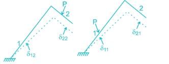
a) δ21 = δ22b) δ22 = δ12c) δ21 = δ11d) δ21= δ12Correct answer is option 'D'. Can you explain this answer?
a) δ21 = δ22
b) δ22 = δ12
c) δ21 = δ11
d) δ21= δ12
Correct answer is option 'D'. Can you explain this answer?

|
Anand Kumar answered |
The Maxwell reciprocal theorem, states that the deflection at a point A in the direction of 1 due to load at point B in the direction of 2 is equal in the magnitude to the deflection of point B in the direction of 2 produced by a load applied at A in direction 1.

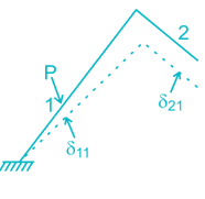


Hence,
δ12 = δ21
Can you guess?

- a)Stark Industries
- b)Avengers
- c)Black-Berry
- d)Motorola
Correct answer is option 'C'. Can you explain this answer?

a)
Stark Industries
b)
Avengers
c)
Black-Berry
d)
Motorola

|
Divyansh Gupta answered |
All are names of industries, however, black-berry is also a fruit, therefore, is odd one here.
A three – hinged parabolic arch rid of span L and crown rise ‘h’ carries a uniformly distributed superimposed load of intensity ‘w’ per unit length. The hinges are located on two abutments at the same level and the third hinge at a quarter span location from the left-hand abutment. The horizontal trust on the abutment is:- a)

- b)

- c)

- d)

Correct answer is option 'C'. Can you explain this answer?
A three – hinged parabolic arch rid of span L and crown rise ‘h’ carries a uniformly distributed superimposed load of intensity ‘w’ per unit length. The hinges are located on two abutments at the same level and the third hinge at a quarter span location from the left-hand abutment. The horizontal trust on the abutment is:
a)

b)

c)

d)


|
Aditya Jain answered |
VA = VB = wL/2
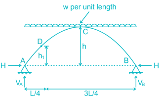


⇒ 4 (h – h1) = h
3h = 4h1
aking moment about hinge at D
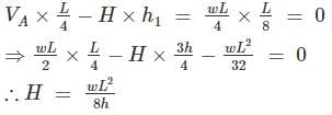
aking moment about hinge at D

The forces in members BE, CD, BC in the truss shown
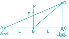
- a)P, P/2,0
- b)P/2, P,0
- c)P, P, P
- d)P/2, P/2,0
Correct answer is option 'A'. Can you explain this answer?
The forces in members BE, CD, BC in the truss shown


a)
P, P/2,0
b)
P/2, P,0
c)
P, P, P
d)
P/2, P/2,0

|
Sahil Chawla answered |

At joint C, there is no horizontal reaction,
So, FBC=0,
Due to Loading Symmetricity,
Va = Vc = P
∴ Vc = P/2
∴ FCD = P/2
Now at joint E,
Due to Loading Symmetricity,
Va = Vc = P
∴ Vc = P/2
∴ FCD = P/2
Now at joint E,
∑Falong the line BE = 0
FBE = P KN
Stiffness coefficient k23 for the beam shown below is

- a)4 EI/L
- b)0
- c)12 EI/L2
- d)6 EI/L2
Correct answer is option 'D'. Can you explain this answer?
Stiffness coefficient k23 for the beam shown below is


a)
4 EI/L
b)
0
c)
12 EI/L2
d)
6 EI/L2

|
Sravya Rane answered |
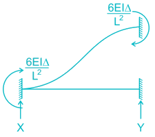
For k33 Apply unit displacement along 3 and restraining the displacement in 2 and 1
Δ → unity

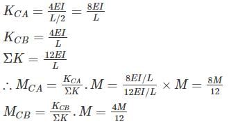
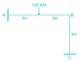
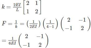
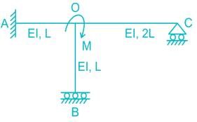
All members of the frame shown below have equal flexural rigidity EI. Calculate the rotation of joint O if moment M is applied?
- a)ML/13EI
- b)2ML/13EI
- c)3ML/13EI
- d)ML/12EI
Correct answer is option 'B'. Can you explain this answer?
All members of the frame shown below have equal flexural rigidity EI. Calculate the rotation of joint O if moment M is applied?


a)
ML/13EI
b)
2ML/13EI
c)
3ML/13EI
d)
ML/12EI

|
Tanishq Nair answered |
Concept :-
Stiffness value, K when far end is fixed = 4EI/L
Stiffness value, K when far end is roller = 3EI/L
Stiffness value, K when far end is guided roller = EI/L
Calculation:-
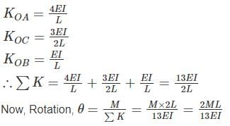
For stiffness coefficient when far end is guided roller support refer :-

For stiffness coefficient when far end is guided roller support refer :-
Advanced Structural Analysis, Prof. Devdas MenonDepartment of Civil Engineering, Indian Institute of Technology, Madras
Module - 5.3 ,Lecture - 29Matrix Analysis of Beams and GridsPage No. - 9
The correct order of strain energy in the beams:-

- a)i < iv < ii < iii
- b)i < ii < iii < iv
- c)iv < iii < ii < i
- d)i < ii < iv < iii
Correct answer is option 'A'. Can you explain this answer?
The correct order of strain energy in the beams:-


a)
i < iv < ii < iii
b)
i < ii < iii < iv
c)
iv < iii < ii < i
d)
i < ii < iv < iii

|
Subhankar Khanna answered |
Deflection, δ = ∂U/∂F
In which beam deflection is higher, strain energy stored will be maximum.
In cantilever, the deflection will be highest.
The deflection of a simply supported beam is higher than propped cantilever as one of the support is fixed.
In a fixed beam, the deflection will be minimum.
So,
δcantilever > δsimple-support > δpropped cantilever > δfixed
∴ Ufixed < Uproped-cantilever < Usimple-support < Ucantliver
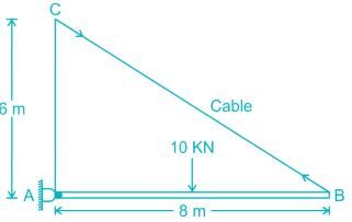
Find the maximum tension in the cable in KN if a unit load of 10 KN can move in either direction in the beam AB?
Correct answer is between '16,17'. Can you explain this answer?
Find the maximum tension in the cable in KN if a unit load of 10 KN can move in either direction in the beam AB?


|
Pallabi Tiwari answered |
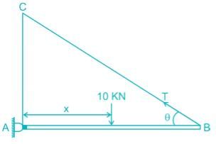
Let the 10 KN load is at a distance x from support A

Taking moment about A
T sin θ × 8 = 10x
⇒ T=
So ‘T’ will be maximum when ‘x’ becomes maximum i.e; x = 8 m

⇒ T=

So ‘T’ will be maximum when ‘x’ becomes maximum i.e; x = 8 m

Find the vertical displacement of joint B if the spring constant k = 1 KN/mm and the rigid beam is loaded as shown below:-

- a)20 mm
- b)30 mm
- c)40 mm
- d)10 mm
Correct answer is option 'C'. Can you explain this answer?
Find the vertical displacement of joint B if the spring constant k = 1 KN/mm and the rigid beam is loaded as shown below:-


a)
20 mm
b)
30 mm
c)
40 mm
d)
10 mm

|
Anagha Mehta answered |
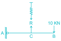
The FBD of the beam will be
Taking moment about A,


Taking moment about A,

R × L = 10 × 2L
R = 20 KN
So the extension of the spring will be
R = Kx
20 = 1. x
x = 20 mm

From similar triangle

From similar triangle
δB = 20 × 2 = 40 mm
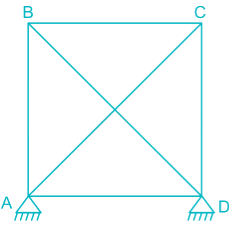
While fabricating a square truss, the member BD was somehow defectively short (fabrication defect) as shown in the figure. So stress developed in the member AC immediately after constructing the truss by force would be
- a)Tensile
- b)compressive
- c)can’t say
- d)zero
Correct answer is option 'A'. Can you explain this answer?
While fabricating a square truss, the member BD was somehow defectively short (fabrication defect) as shown in the figure. So stress developed in the member AC immediately after constructing the truss by force would be


a)
Tensile
b)
compressive
c)
can’t say
d)
zero

|
Partho Jain answered |
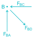
At joint B, FBC → Compressive
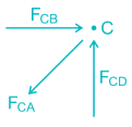
At joitnt C, FCA → Tensile
Chapter doubts & questions for Structural Analysis - RRB JE for Civil Engineering 2025 is part of Civil Engineering (CE) exam preparation. The chapters have been prepared according to the Civil Engineering (CE) exam syllabus. The Chapter doubts & questions, notes, tests & MCQs are made for Civil Engineering (CE) 2025 Exam. Find important definitions, questions, notes, meanings, examples, exercises, MCQs and online tests here.
Chapter doubts & questions of Structural Analysis - RRB JE for Civil Engineering in English & Hindi are available as part of Civil Engineering (CE) exam.
Download more important topics, notes, lectures and mock test series for Civil Engineering (CE) Exam by signing up for free.
RRB JE for Civil Engineering
1 docs|42 tests
|
Signup to see your scores go up within 7 days!
Study with 1000+ FREE Docs, Videos & Tests
10M+ students study on EduRev

Contact Support
Our team is online on weekdays between 10 AM - 7 PM
Typical reply within 3 hours
|
Free Exam Preparation
at your Fingertips!
Access Free Study Material - Test Series, Structured Courses, Free Videos & Study Notes and Prepare for Your Exam With Ease

 Join the 10M+ students on EduRev
|

|
Forgot Password
OR
Signup to see your scores
go up
within 7 days!
within 7 days!
Takes less than 10 seconds to signup

