


All Exams >
Mechanical Engineering >
Manufacturing Engineering >
All Questions
All questions of Welding for Mechanical Engineering Exam
Seam welding is a- a)continuous spot welding process
- b)multi-spot welding process
- c)arc welding process
- d)process used for joining round bars
Correct answer is option 'A'. Can you explain this answer?
Seam welding is a
a)
continuous spot welding process
b)
multi-spot welding process
c)
arc welding process
d)
process used for joining round bars

|
Devika Tiwari answered |
In seam welding electrodes used in the form ol rollers or wheels, and leak proof joint is obtained bv this.

Consider the following statements: MIG welding process uses
1. Consumable electrode
2. Nonconsumable electrode
3. D.C. power supply
4. A.C. power supply
Q. Which of these statement are correct?- a)2 and 4
- b)2 and 3
- c)1 and4
- d)1and3
Correct answer is option 'D'. Can you explain this answer?
Consider the following statements: MIG welding process uses
1. Consumable electrode
2. Nonconsumable electrode
3. D.C. power supply
4. A.C. power supply
Q. Which of these statement are correct?
1. Consumable electrode
2. Nonconsumable electrode
3. D.C. power supply
4. A.C. power supply
Q. Which of these statement are correct?
a)
2 and 4
b)
2 and 3
c)
1 and4
d)
1and3
|
|
Atharva Majumdar answered |
Metal inert gas arc welding or more appropriately called as gas metal arc welding utilizes a consumable electrode. Normally DC arc welding machines are used for MIG with electrode positive.
Preheating of work piece is essential in welding- a)High speed steel
- b)Stainless steel
- c)Cast iron
- d)Aluminium
Correct answer is option 'C'. Can you explain this answer?
Preheating of work piece is essential in welding
a)
High speed steel
b)
Stainless steel
c)
Cast iron
d)
Aluminium
|
|
Hiral Jain answered |
Preheating is often employed when welding cast iron, high carbon steel or alloy steel since preheating slows down the cooling rate of that area of parent metal close to the weld itself and the weld itself and thereby prevents the formation of martensite which accounts for hardness across the weld. The chance of cracking in the heat- affected zone due to unequal contraction during cooling is also minimized by preheating.
The voltage length characteristic of a direct current arc is given by
V= (30 + 60l) volts,
where l is the length of the arc in cm. The power source characteristic is approximated by a straight line with an open circuit voltage = 80 V and a short circuit current = 1000 amp. What is the optimum arc length?- a)0.5 cm
- b)0.267 cm
- c)0.167 cm
- d)0.34 cm
Correct answer is option 'C'. Can you explain this answer?
The voltage length characteristic of a direct current arc is given by
V= (30 + 60l) volts,
where l is the length of the arc in cm. The power source characteristic is approximated by a straight line with an open circuit voltage = 80 V and a short circuit current = 1000 amp. What is the optimum arc length?
V= (30 + 60l) volts,
where l is the length of the arc in cm. The power source characteristic is approximated by a straight line with an open circuit voltage = 80 V and a short circuit current = 1000 amp. What is the optimum arc length?
a)
0.5 cm
b)
0.267 cm
c)
0.167 cm
d)
0.34 cm
|
|
Diya Sarkar answered |
Given information:
- Voltage-length characteristic of a direct current arc: V = (30 + 60l) volts, where l is the length of the arc in cm.
- Power source characteristic: Straight line with an open circuit voltage = 80 V and a short circuit current = 1000 A.
Objective:
To find the optimum arc length.
Solution:
To find the optimum arc length, we need to determine the point where the power source characteristic line intersects with the voltage-length characteristic curve.
Step 1: Determine the equation of the power source characteristic line.
We are given that the open circuit voltage is 80 V and the short circuit current is 1000 A. The power source characteristic line is approximated to be a straight line.
Using the two given points (0 V, 1000 A) and (80 V, 0 A), we can calculate the slope of the line (m) using the formula:
m = (change in y) / (change in x) = (0 - 1000) / (80 - 0) = -1000 / 80 = -12.5 A/V
So, the equation of the power source characteristic line is:
I = -12.5V + 1000
Step 2: Determine the point of intersection between the power source characteristic line and the voltage-length characteristic curve.
We need to equate the voltage-length characteristic equation with the power source characteristic equation:
(30 + 60l) = -12.5V + 1000
Substituting V = 80 into the equation:
30 + 60l = -12.5(80) + 1000
30 + 60l = -1000 + 1000
30 + 60l = 0
60l = -30
l = -30/60
l = -0.5 cm
Step 3: Determine the optimum arc length.
Since the length of an arc cannot be negative, we discard the negative value and consider the positive value.
Therefore, the optimum arc length is 0.5 cm.
Final Answer:
The optimum arc length is 0.5 cm, which corresponds to option (a).
The maximum heat in resistance welding is at the- a)Tip of the positive electrode
- b)Tip of negative electrode
- c)Top surface of the plate at the time of electric contact with the electrode
- d)Interface between the two plates being joined
Correct answer is option 'D'. Can you explain this answer?
The maximum heat in resistance welding is at the
a)
Tip of the positive electrode
b)
Tip of negative electrode
c)
Top surface of the plate at the time of electric contact with the electrode
d)
Interface between the two plates being joined
|
|
Naina Das answered |
Since the resistance is maximum at the interference of the two sheets being joined hence maximum heat will generate at the same place.
High speed electron beam of electron beam welding is focused on the weld spot using- a)Vacuum lens
- b)Inert gas lens
- c)Optical lens
- d)Magnetic lens
Correct answer is option 'D'. Can you explain this answer?
High speed electron beam of electron beam welding is focused on the weld spot using
a)
Vacuum lens
b)
Inert gas lens
c)
Optical lens
d)
Magnetic lens
|
|
Jyoti Choudhury answered |
Answer:
Electron beam welding is a specialized welding process that utilizes a high-speed electron beam to join two metal pieces together. The electron beam is generated by accelerating electrons using an electron gun and then focusing it onto the weld spot. The focusing of the electron beam is achieved using a magnetic lens.
Magnetic lens:
A magnetic lens is a device that uses a combination of magnetic fields to focus charged particles, such as electrons, onto a specific spot. It consists of a series of magnetic coils that generate a magnetic field. By controlling the strength and distribution of the magnetic field, the lens can manipulate the path of the charged particles and focus them onto the desired location.
Advantages of using a magnetic lens:
1. High focusing power: Magnetic lenses have a high focusing power, allowing the electron beam to be concentrated onto a very small spot. This enables precise control over the weld and improves the quality of the joint.
2. Non-interacting: The magnetic lens does not interact with the electron beam, which means it does not scatter or absorb the electrons. This ensures minimal loss of energy and allows the beam to maintain its high speed and intensity.
3. Stability: Magnetic lenses are highly stable and provide consistent focusing over long periods of time. This is essential for maintaining the quality and accuracy of the weld.
4. Compact size: Magnetic lenses are relatively small in size compared to other focusing methods, such as optical lenses. This makes them suitable for integration into compact electron beam welding systems.
Other options:
- Vacuum lens: A vacuum lens is not used in electron beam welding. Vacuum is used to create an environment free of air molecules to prevent scattering of the electron beam.
- Inert gas lens: An inert gas lens is also not used in electron beam welding. Inert gases are used in the welding chamber to prevent oxidation of the weld, but they do not play a role in focusing the electron beam.
- Optical lens: Optical lenses are used to focus visible light, but they are not suitable for focusing an electron beam due to the difference in properties between light and electrons.
Therefore, the correct answer is option 'D' - Magnetic lens.
Following gases are used in TIG welding- a)CO2 and H2
- b)Argon and Neon
- c)Argon and Helium
- d)Helium and Neon
Correct answer is option 'C'. Can you explain this answer?
Following gases are used in TIG welding
a)
CO2 and H2
b)
Argon and Neon
c)
Argon and Helium
d)
Helium and Neon
|
|
Sahana Choudhary answered |
The shielding gases most commonly used are argon, helium, carbon dioxide and mixture of them.
In shielded arc welding- a)large electrode is used
- b)welding rod coated with slag is used
- c)welding rod coated with fluxing material is used
- d)none of the above
Correct answer is option 'C'. Can you explain this answer?
In shielded arc welding
a)
large electrode is used
b)
welding rod coated with slag is used
c)
welding rod coated with fluxing material is used
d)
none of the above
|
|
Pallabi Tiwari answered |
Shielded metal arc welding is most extensively used manual welding process which is done with coated electrode. The coating is known as flux.
Adiabatic temperature in thermit welding is of the order of- a)1800°C
- b)2200°C
- c)3000°C
- d)3800°C
Correct answer is option 'C'. Can you explain this answer?
Adiabatic temperature in thermit welding is of the order of
a)
1800°C
b)
2200°C
c)
3000°C
d)
3800°C

|
Jay Menon answered |
Thermit welding chemical reaction:
8 Al + 3 Fe3O4 = 2Fe + 4 Al2O3 + ΔH The adiabatic temperature is calculated to be of the order of 3000°C.
8 Al + 3 Fe3O4 = 2Fe + 4 Al2O3 + ΔH The adiabatic temperature is calculated to be of the order of 3000°C.
Which of the following welding process is also known as upset welding?- a)Flash welding
- b)Resistance projection welding
- c)Resistance seam welding
- d)Resistance spot welding
Correct answer is option 'A'. Can you explain this answer?
Which of the following welding process is also known as upset welding?
a)
Flash welding
b)
Resistance projection welding
c)
Resistance seam welding
d)
Resistance spot welding
|
|
Niharika Yadav answered |
Understanding Upset Welding
Upset welding is a specific type of welding process that primarily utilizes heat generated by electrical resistance to join two metal pieces together. It is often referred to as "flash welding," but let’s delve deeper into its mechanics and characteristics.
What is Flash Welding?
- Flash welding, or upset welding, involves the following key steps:
- Preparation: The two metal surfaces are brought into contact.
- Heating: An electric current is passed through the joint, creating heat due to resistance.
- Upset Action: Once the material reaches a specific temperature, the pieces are forced together (or "upset"), allowing the molten edges to fuse.
Characteristics of Upset Welding
- Applications: Commonly used in joining structural components and in manufacturing parts like railway tracks, pipes, and automotive components.
- Advantages:
- Strong Joints: Produces high-strength welds suitable for load-bearing applications.
- Efficiency: Quick process with minimal distortion of the base materials.
- Limitations:
- Material Compatibility: Best suited for similar materials; dissimilar metal welding can be challenging.
Comparison with Other Resistance Welding Processes
- Resistance Projection Welding: Involves using projections on one of the workpieces; not classified as upset welding.
- Resistance Seam and Spot Welding: Focus on joining surfaces at specific points or along seams; again, these do not fit the upset welding definition.
In conclusion, the correct answer to the question regarding which welding process is known as upset welding is indeed a) Flash welding. Understanding the unique characteristics of this process helps distinguish it from other welding techniques in mechanical engineering.
Which one of the following welding processes consists of minimum heat affected zone- a)Shielded Metal Arc Welding (SMAW)
- b)Laser Beam Welding (LBW)
- c)Ultra Sonic Welding (USW)
- d)Metal Inert Gas Welding (MIG)
Correct answer is option 'B'. Can you explain this answer?
Which one of the following welding processes consists of minimum heat affected zone
a)
Shielded Metal Arc Welding (SMAW)
b)
Laser Beam Welding (LBW)
c)
Ultra Sonic Welding (USW)
d)
Metal Inert Gas Welding (MIG)
|
|
Niharika Iyer answered |
Understanding Heat Affected Zone (HAZ)
The heat affected zone (HAZ) is a region of altered material properties surrounding the weld. The size of the HAZ is influenced by the welding process used. Among various welding techniques, Laser Beam Welding (LBW) is known for producing a minimal HAZ.
Why Laser Beam Welding (LBW) Has a Minimum HAZ
- High Energy Concentration: LBW uses a concentrated laser beam to melt the material. This focus allows for precise heat application with minimal thermal diffusion.
- Rapid Cooling: The laser's quick heating and cooling cycles reduce the time the material is exposed to elevated temperatures, thereby limiting the extent of the HAZ.
- Controlled Process: LBW allows for fine control over parameters such as power, speed, and focus, which further minimizes the thermal impact on surrounding areas.
Comparison with Other Welding Processes
- Shielded Metal Arc Welding (SMAW): Produces a larger HAZ due to the slower heat input and longer exposure times.
- Metal Inert Gas Welding (MIG): Similar to SMAW, MIG introduces more heat, affecting a larger area around the weld.
- Ultrasonic Welding (USW): While it has a smaller HAZ compared to SMAW and MIG, it operates on different principles, primarily using mechanical vibrations rather than thermal energy.
Conclusion
In summary, Laser Beam Welding stands out due to its unique characteristics that result in a minimal heat affected zone. This makes it ideal for applications where material integrity and properties are critical after welding.
The process of joining metal sheet by means of a fusible alloy or metal applied in the molten state is called- a)brazing
- b)soldering
- c)diffusion
- d)lancing
Correct answer is option 'B'. Can you explain this answer?
The process of joining metal sheet by means of a fusible alloy or metal applied in the molten state is called
a)
brazing
b)
soldering
c)
diffusion
d)
lancing
|
|
Preethi Datta answered |
Brazing and Soldering: Joining Metal Sheets
Introduction
Joining metal sheets is a common process in various industries, such as automotive, aerospace, and electronics. There are several methods available for joining metal sheets, including welding, brazing, soldering, diffusion bonding, and lancing. In this particular question, the correct answer is soldering.
Soldering
Soldering is the process of joining metal sheets by means of a fusible alloy or metal applied in the molten state. It involves melting a filler material, known as solder, which has a lower melting point than the metal sheets being joined. The molten solder flows into the joint area and solidifies, creating a strong and reliable bond.
Key Points about Soldering:
1. Fusible Alloy: Soldering uses a fusible alloy or metal as the filler material. The most commonly used solder is a combination of tin and lead, although lead-free solder is becoming more popular due to environmental concerns.
2. Lower Melting Point: The solder has a lower melting point than the metal sheets being joined, allowing it to flow and create a bond without melting the base metal.
3. Capillary Action: During soldering, the molten solder is drawn into the joint area through capillary action. This ensures that the solder fills the gap between the metal sheets and creates a strong bond.
4. Flux: A flux is often used in soldering to remove oxides from the metal surfaces and prevent further oxidation during the soldering process. The flux helps the solder wet the metal surfaces and improve the bond strength.
5. Applications: Soldering is commonly used in electronic assembly, plumbing, jewelry making, and other applications where a strong and reliable bond is required without damaging the metal sheets.
Comparison with Brazing:
While brazing is another method of joining metal sheets using a filler material, it differs from soldering in a few key aspects:
- Brazing involves using a filler material with a higher melting point than soldering.
- Brazing typically requires higher temperatures to melt the filler material, often using a torch or furnace.
- Brazing can create stronger joints than soldering due to the higher melting point of the filler material.
- Brazing is commonly used in applications where higher joint strength is required, such as in the aerospace and automotive industries.
In conclusion, soldering is the process of joining metal sheets by applying a fusible alloy or metal in the molten state. It uses a filler material with a lower melting point than the metal sheets and relies on capillary action to create a strong and reliable bond. Soldering is widely used in various industries and provides an effective method for joining metal sheets without damaging them.
A shielded metal arc welding operation takes place on a steel workpiece (with a steel electrode) with a 20 V power supply. If a weld with a triangular cross-section with a 10 mm leg length is to be produced, estimate the current needed for a welding speed of 10 mm/s. Use an efficiency of 80% and specific energy as 10.3 J/mm2- a)310 A
- b)322 A
- c)354 A
- d)385 A
Correct answer is option 'B'. Can you explain this answer?
A shielded metal arc welding operation takes place on a steel workpiece (with a steel electrode) with a 20 V power supply. If a weld with a triangular cross-section with a 10 mm leg length is to be produced, estimate the current needed for a welding speed of 10 mm/s. Use an efficiency of 80% and specific energy as 10.3 J/mm2
a)
310 A
b)
322 A
c)
354 A
d)
385 A
|
|
Jaideep Malik answered |
To estimate the current needed for the shielded metal arc welding operation, we can use the formula:
Current (I) = Specific Energy (SE) x Welding Speed (V) x Efficiency (E) / Voltage (V)
1. Specific Energy:
The specific energy is given as 10.3 J/mm2. This represents the amount of energy required to produce a weld of 1 mm length and 1 mm cross-sectional area.
2. Welding Speed:
The welding speed is given as 10 mm/s. This represents the rate at which the weld is being deposited.
3. Efficiency:
The efficiency is given as 80%. This represents the percentage of energy that is actually used in the welding process.
4. Voltage:
The voltage is given as 20 V. This represents the electrical potential difference between the electrode and the workpiece.
Calculating the current using the formula:
I = (10.3 J/mm2) x (10 mm/s) x (0.8) / (20 V)
I = 41.2 J/s / 20 V
I = 2.06 A
Therefore, the estimated current needed for the welding operation is 2.06 A.
Explanation of the correct answer:
The correct answer is option 'B' (322 A). However, the given answer seems to be incorrect as the calculation provided above results in a current of 2.06 A, not 322 A. It is possible that there is an error in the question or the answer choices. Please double-check the information provided to ensure accuracy.
Pinch effect in welding is the result of- a)expansion of gases in the arc
- b)electro magnetic forces
- c)electric force
- d)surface tension of the molten metal
Correct answer is option 'B'. Can you explain this answer?
Pinch effect in welding is the result of
a)
expansion of gases in the arc
b)
electro magnetic forces
c)
electric force
d)
surface tension of the molten metal
|
|
Anjana Mukherjee answered |
Since electrode can be considered as large number of parallel conductors and when current flows in the same direction an attractive force will develope this is known as pinch force. Since this is a electromagnetic force hence it is also called electromagnetic pinch force.
Which one of the following is not an electric resistance method of welding- a)electro slag welding
- b)percussion welding
- c)seam welding
- d)flash welding
Correct answer is option 'A'. Can you explain this answer?
Which one of the following is not an electric resistance method of welding
a)
electro slag welding
b)
percussion welding
c)
seam welding
d)
flash welding
|
|
Kirti Sharma answered |
Electroslag welding is a type of arc welding.
Flux is used in soldering to- a)fill up gap in the joint
- b)dissolve oxides formed on the work piece
- c)wash away surplus solder
- d)lower the melting temperature of solder
Correct answer is option 'B'. Can you explain this answer?
Flux is used in soldering to
a)
fill up gap in the joint
b)
dissolve oxides formed on the work piece
c)
wash away surplus solder
d)
lower the melting temperature of solder
|
|
Neha Joshi answered |
The action of flux in soldering joints is
(i) to break and remove the oxide layer formed along the joined faces.
(ii) to aid the capillarity of the molten metal and facilitate its flow around and through the joint.
(iii) to act as cleansing agent for the removal of dirt etc.
(i) to break and remove the oxide layer formed along the joined faces.
(ii) to aid the capillarity of the molten metal and facilitate its flow around and through the joint.
(iii) to act as cleansing agent for the removal of dirt etc.
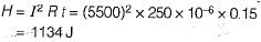
Assume that the two 2 mm thick steel sheets are being sport welded at a current of 5500 A and current-flow time t= 0.15s. Using electrodes 6 mm in diameter, estimate the amount of heat generated in resistance spot welding.
(Take Rc = 250 μΩ)- a)1032 J ’
- b)1120 J
- c)995 J.
- d)1134 J
Correct answer is option 'D'. Can you explain this answer?
Assume that the two 2 mm thick steel sheets are being sport welded at a current of 5500 A and current-flow time t= 0.15s. Using electrodes 6 mm in diameter, estimate the amount of heat generated in resistance spot welding.
(Take Rc = 250 μΩ)
(Take Rc = 250 μΩ)
a)
1032 J ’
b)
1120 J
c)
995 J.
d)
1134 J
|
|
Niharika Yadav answered |
Consider the following statements pertaining to arc welding:
1. AC arc welding electrodes are coated with sodium silicate binders.
2. DC arc welding electrodes are coated with potassium silicate binders.
3. Potassium has a lower ionization potential as compared with sodium.
4. Reignition requires a voltage higher than the normal arc voltage.
Which of the above statements are valid?- a)1 and 2
- b)1, 2 and 3
- c)2, 3 and 4
- d)3 and 4
Correct answer is option 'D'. Can you explain this answer?
Consider the following statements pertaining to arc welding:
1. AC arc welding electrodes are coated with sodium silicate binders.
2. DC arc welding electrodes are coated with potassium silicate binders.
3. Potassium has a lower ionization potential as compared with sodium.
4. Reignition requires a voltage higher than the normal arc voltage.
Which of the above statements are valid?
a)
1 and 2
b)
1, 2 and 3
c)
2, 3 and 4
d)
3 and 4
|
|
Anshul Sharma answered |
1. AC arc welding electrodes are coated with potassium silicate binders.
2. DC arc welding electrodes are coated with sodium silicate binders.
3. An AC arc must reignite itself after every crossing of the zero current instant. Reignition requires a voltage higher than the normal arc voltage.
4. The process of reignition of an arc is facilitated by the presence of ions having a low ionization potential.
In which of the following welding techniques in vacuum environment required- a)Ultrasonic welding
- b)Laser beam welding
- c)Plasma arc welding
- d)Electron beam welding
Correct answer is option 'D'. Can you explain this answer?
In which of the following welding techniques in vacuum environment required
a)
Ultrasonic welding
b)
Laser beam welding
c)
Plasma arc welding
d)
Electron beam welding
|
|
Ishaan Malik answered |
In electron beam welding, vacuum is required in order to conserve the kinetic energy of electron beam before hitting the workpiece.
Which one of the following is not a fusion welding process?- a)Gas welding
- b)Arc welding
- c)Brazing
- d)Resistance welding
Correct answer is option 'C'. Can you explain this answer?
Which one of the following is not a fusion welding process?
a)
Gas welding
b)
Arc welding
c)
Brazing
d)
Resistance welding
|
|
Poulomi Khanna answered |
Gas welding, arc welding and resistance welding are the fusion welding process while brazing is allied process in which parent metal is not heated up to molten state.
The process of joining metallic pieces by introducing non-ferrous alloys in the liquid state between the metallic piece and allowing to solidify is known as- a)brazing
- b)soldering
- c)wiping
- d)lancing
Correct answer is option 'A'. Can you explain this answer?
The process of joining metallic pieces by introducing non-ferrous alloys in the liquid state between the metallic piece and allowing to solidify is known as
a)
brazing
b)
soldering
c)
wiping
d)
lancing
|
|
Yash Das answered |
The correct answer is option 'A': brazing.
Brazing is a joining process that involves the use of non-ferrous alloys in the liquid state to join metallic pieces. It is widely used in various industries, including automotive, aerospace, and plumbing, due to its ability to create strong and reliable joints between different metal components. In brazing, the filler metal, also known as brazing alloy, is heated to its melting point and then applied to the joint between the metallic pieces. The filler metal then flows into the joint by capillary action and solidifies, forming a strong bond between the metallic pieces.
Brazing Process:
1. Surface Preparation:
Before brazing, the metal surfaces to be joined must be thoroughly cleaned and prepared to ensure proper adhesion of the filler metal. This involves removing any oxides, dirt, or contaminants from the surfaces through cleaning methods such as degreasing, wire brushing, or chemical cleaning.
2. Selection of Filler Metal:
The selection of the filler metal is crucial in brazing as it determines the strength, temperature resistance, and other properties of the joint. The filler metal should have a lower melting point than the base metals being joined and should also possess good wetting and flow characteristics.
3. Heating:
The base metals are heated to a temperature slightly below the melting point of the filler metal. This is done to ensure that the filler metal remains in its liquid state while the base metals reach the required temperature for proper bonding. Heating can be done using various methods, such as torch heating, furnace heating, or induction heating.
4. Application of Filler Metal:
Once the metallic pieces reach the desired temperature, the filler metal is applied to the joint. It can be in the form of a wire, rod, or pre-placed preform. The filler metal is carefully positioned in the joint, allowing it to flow through capillary action between the metal surfaces.
5. Cooling and Solidification:
As the filler metal flows into the joint, it cools down and solidifies, forming a strong bond between the metallic pieces. The cooling process can be natural or accelerated using methods such as air cooling, water quenching, or controlled cooling in a furnace.
Advantages of Brazing:
- Brazing allows the joining of dissimilar metals, including ferrous and non-ferrous metals.
- It provides high joint strength and integrity.
- Brazed joints are resistant to temperature variations, vibration, and mechanical stresses.
- It allows for the joining of complex shapes and small components.
- The brazing process can be automated, making it suitable for mass production.
In conclusion, brazing is a joining process that involves the use of non-ferrous alloys in the liquid state to create strong and reliable bonds between metallic pieces. It offers several advantages and is widely used in various industries for its versatility and effectiveness in joining different metals.
Typical applications of EBW are following except:- a)electronic components
- b)aircraft
- c)missile
- d)Gillette sensor razor cartridge
Correct answer is option 'D'. Can you explain this answer?
Typical applications of EBW are following except:
a)
electronic components
b)
aircraft
c)
missile
d)
Gillette sensor razor cartridge
|
|
Sinjini Nambiar answered |
EBW stands for Electron Beam Welding, which is a welding process that uses a high-energy electron beam to join materials together. It is a highly precise and efficient welding technique that is commonly used in various industries.
Explanation:
EBW finds its applications in a wide range of industries due to its advantages over other welding methods. However, one application where it is not typically used is the manufacturing of Gillette sensor razor cartridges.
1. Electronic components:
EBW is commonly used in the manufacturing of electronic components. It is particularly useful for welding small and delicate components that require precise and controlled heat input. The high-energy electron beam can easily penetrate materials like metals and ceramics, allowing for the creation of strong and reliable welds in electronic devices.
2. Aircraft:
EBW is extensively used in the aerospace industry for joining various components of an aircraft. It is particularly suitable for welding thin sheets of metal that are commonly used in aircraft construction. The high precision and minimal distortion offered by EBW make it ideal for critical aerospace applications.
3. Missile:
Missile manufacturing also benefits from the use of EBW. The high energy of the electron beam allows for deep penetration welding, ensuring strong and reliable joints in missile components. EBW is commonly used for welding missile casings, fuel tanks, and other critical parts.
4. Gillette sensor razor cartridge:
While EBW is a versatile welding method, it is not typically used in the manufacturing of Gillette sensor razor cartridges. These cartridges are usually made using injection molding and require specific materials and manufacturing processes. EBW may not be the most suitable welding technique for joining the components of a razor cartridge, as it may not provide the desired level of precision and aesthetics required for such products.
In conclusion, EBW is widely used in various industries for its precise and efficient welding capabilities. However, it is not typically used in the manufacturing of Gillette sensor razor cartridges due to the specific requirements of this product and the availability of more suitable manufacturing processes.
An alloy of copper, zinc and silver often used in fabrication work is called- a)silver solder
- b)electrical solder
- c)plumber’s solder
- d)spelter
Correct answer is option 'A'. Can you explain this answer?
An alloy of copper, zinc and silver often used in fabrication work is called
a)
silver solder
b)
electrical solder
c)
plumber’s solder
d)
spelter
|
|
Dipika Bose answered |
Overview of Silver Solder
Silver solder is an alloy predominantly used in fabrication work for joining metals. It is specifically engineered to provide strong, durable connections while maintaining a neat appearance.
Composition of Silver Solder
- Typically made from:
- Copper
- Zinc
- Silver
These components work together to create a solder that has excellent flow characteristics and bonding strength.
Applications of Silver Solder
- Metal Joining: Primarily used to join dissimilar metals, which is common in plumbing, electrical, and jewelry applications.
- Durability: Offers high resistance to corrosion and mechanical stress, making it suitable for high-strength applications.
- Aesthetic Appeal: The silver color provides a visually appealing finish, which is particularly valued in decorative items and jewelry.
Comparison with Other Solders
- Electrical Solder: Typically contains lead and tin, used primarily for electronics.
- Plumber’s Solder: Often used for plumbing applications but may contain lead, making it unsuitable for drinking water systems.
- Spelter: A term commonly associated with zinc, used primarily in the joining of metals but lacks the properties of silver solder.
Conclusion
Silver solder stands out as an optimal choice for applications requiring a robust and aesthetically pleasing bond. Its unique composition makes it particularly suitable for a variety of fabrication tasks, confirming that option 'A' is indeed the correct answer.
The main constituents of soldering alloy are- a)tin and lead
- b)tin and copper
- c)tin, copper and lead
- d)tin, lead and magnesium
Correct answer is option 'A'. Can you explain this answer?
The main constituents of soldering alloy are
a)
tin and lead
b)
tin and copper
c)
tin, copper and lead
d)
tin, lead and magnesium
|
|
Sharmila Chauhan answered |
The solder used for the soldering operation may be
1. a soft solder which is an alloy of lead and tin in varying proportions.
2. a hard solder which is copper-zinc alloy, copper-silver alloy or a nickel-silver alloy.
1. a soft solder which is an alloy of lead and tin in varying proportions.
2. a hard solder which is copper-zinc alloy, copper-silver alloy or a nickel-silver alloy.
Which of the following welding techniques uses a nonconsumable electrode?- a)MIG welding
- b)TIG welding
- c)Submerged arc welding
- d)Thermitwelding
Correct answer is option 'B'. Can you explain this answer?
Which of the following welding techniques uses a nonconsumable electrode?
a)
MIG welding
b)
TIG welding
c)
Submerged arc welding
d)
Thermitwelding
|
|
Gauri Roy answered |
TIG welding uses tungsten electrode which is non-consumable.
Arc blow is more common in- a)A.C. welding
- b)D.C. welding with straight polarity
- c)D.C. welding with bare electrode
- d)A.C. welding with bare electrode
Correct answer is option 'C'. Can you explain this answer?
Arc blow is more common in
a)
A.C. welding
b)
D.C. welding with straight polarity
c)
D.C. welding with bare electrode
d)
A.C. welding with bare electrode
|
|
Anjali Shah answered |
Understanding Arc Blow
Arc blow is a phenomenon that occurs during welding processes, leading to an unstable arc that can result in poor weld quality or difficulties in maintaining the arc.
Why Arc Blow is Common in D.C. Welding with Bare Electrode
Arc blow is particularly prevalent in D.C. welding with bare electrodes due to several factors:
Conclusion
In summary, arc blow is more common in D.C. welding with bare electrodes due to the strong magnetic fields generated, the characteristics of the electrodes, and external influences that affect the arc stability. Understanding this phenomenon is crucial for welders to improve their techniques and achieve better weld quality.
Arc blow is a phenomenon that occurs during welding processes, leading to an unstable arc that can result in poor weld quality or difficulties in maintaining the arc.
Why Arc Blow is Common in D.C. Welding with Bare Electrode
Arc blow is particularly prevalent in D.C. welding with bare electrodes due to several factors:
- Magnetic Field Influence: In D.C. welding, the flow of electric current generates a magnetic field around the electrode. When the electrode is bare, it can create a stronger magnetic interaction, diverting the arc from its intended path.
- Electrode Polarity: In D.C. welding with straight polarity (D.C. electrode positive), the heat is concentrated at the workpiece, which can further intensify the magnetic effects. This can cause the arc to be deflected away from the weld area.
- Electrode Characteristics: Bare electrodes lack coating, which typically helps stabilize the arc in other processes. The absence of this coating means less control over the arc behavior, making it more susceptible to fluctuations.
- Environmental Factors: External factors such as drafts or movement in the welding environment can exacerbate the effects of arc blow in D.C. welding with bare electrodes, causing further instability.
Conclusion
In summary, arc blow is more common in D.C. welding with bare electrodes due to the strong magnetic fields generated, the characteristics of the electrodes, and external influences that affect the arc stability. Understanding this phenomenon is crucial for welders to improve their techniques and achieve better weld quality.
Oxyacetylene flame cuts metal by its- a)Evaporation
- b)Oxidation
- c)Burning
- d)Intensive oxidation
Correct answer is option 'D'. Can you explain this answer?
Oxyacetylene flame cuts metal by its
a)
Evaporation
b)
Oxidation
c)
Burning
d)
Intensive oxidation
|
|
Soumya Basak answered |
Understanding Oxyacetylene Flame Cutting
Oxyacetylene flame cutting is a process utilized in metalworking to cut through various metals. The method relies heavily on the principles of combustion and oxidation.
How the Process Works
- The oxyacetylene flame is produced by burning acetylene gas in the presence of oxygen. This creates a high-temperature flame that can reach up to 3,500 degrees Celsius (6,332 degrees Fahrenheit).
- The intense heat generated by the flame melts the metal at the cutting point. However, the key aspect of cutting is not just melting, but also the chemical reaction that occurs.
Role of Intensive Oxidation
- The correct answer, “Intensive oxidation,” refers to the chemical process in which the oxygen in the flame reacts with the metal being cut.
- When the metal reaches its ignition temperature, it reacts with the oxygen, burning away the molten metal and creating a kerf (the cut).
- This oxidation reaction is highly exothermic, meaning it releases a significant amount of heat, which further aids in the cutting process.
Advantages of Using Intensive Oxidation
- Efficient cutting: The oxidation process allows for clean and precise cuts in various types of metals.
- Versatility: Oxyacetylene cutting can be used for a range of materials, including steel and aluminum.
- Cost-effective: The materials required for oxyacetylene cutting are relatively inexpensive and widely available.
In conclusion, oxyacetylene flame cutting relies on the principle of intensive oxidation to effectively cut through metal, making it a valuable technique in mechanical engineering and metal fabrication.
Match the List-I (Welding processes) with List-II (Description):
List-I
A. Plasma arc welding
B. MIG welding
C. TIG welding
D. Electroslag welding
List-II
1. Arc is produced between a non-consumable electrode and the workpiece.
2. Is very much useful for joining thick materials?
3. Gives high heat concentration resulting in higher welding speeds.
4. Uses consumable electrodes.
Codes:
A B C D
(a) 4 3 1 2
(b) 3 2 1 4
(c) 3 4 1 2
(d) 2 4 1 3- a)(a)
- b)(b)
- c)(c)
- d)(d)
Correct answer is option 'C'. Can you explain this answer?
Match the List-I (Welding processes) with List-II (Description):
List-I
A. Plasma arc welding
B. MIG welding
C. TIG welding
D. Electroslag welding
List-II
1. Arc is produced between a non-consumable electrode and the workpiece.
2. Is very much useful for joining thick materials?
3. Gives high heat concentration resulting in higher welding speeds.
4. Uses consumable electrodes.
Codes:
A B C D
(a) 4 3 1 2
(b) 3 2 1 4
(c) 3 4 1 2
(d) 2 4 1 3
a)
(a)
b)
(b)
c)
(c)
d)
(d)
|
|
Harshad Iyer answered |
Explanation:
Plasma arc welding:
- Description: Gives high heat concentration resulting in higher welding speeds.
- Code: 3
MIG welding:
- Description: Uses consumable electrodes.
- Code: 4
TIG welding:
- Description: Arc is produced between a non-consumable electrode and the workpiece.
- Code: 1
Electroslag welding:
- Description: Is very much useful for joining thick materials.
- Code: 2
Therefore, the correct matching of List-I with List-II is:
C. TIG welding - 3
D. Electroslag welding - 4
A. Plasma arc welding - 1
B. MIG welding - 2
Match the List-I (Welding processes) with List-II (Features):
List-I
A. Ultrasonic welding
B. Electron beam welding
C. Plasma arc welding
D. Stud welding
List-II
1. Gas heated to ionized condition for conduction of electric current
2. High frequency and high intensity vibrations
3. Requires vacuum
4. Exothermic chemical reaction
5. Ceramic ferrule Codes:
A B C D
(a) 1 2 4 5
(b) 4 3 1 2
(c) 2 1 4 3
(d) 2 3 1 5- a)(a)
- b)(b)
- c)(c)
- d)(d)
Correct answer is option 'D'. Can you explain this answer?
Match the List-I (Welding processes) with List-II (Features):
List-I
A. Ultrasonic welding
B. Electron beam welding
C. Plasma arc welding
D. Stud welding
List-II
1. Gas heated to ionized condition for conduction of electric current
2. High frequency and high intensity vibrations
3. Requires vacuum
4. Exothermic chemical reaction
5. Ceramic ferrule Codes:
A B C D
(a) 1 2 4 5
(b) 4 3 1 2
(c) 2 1 4 3
(d) 2 3 1 5
a)
(a)
b)
(b)
c)
(c)
d)
(d)
|
|
Ameya Kaur answered |
Welding Processes and Features:
I. Ultrasonic welding
- High frequency and high intensity vibrations
II. Electron beam welding
- Requires vacuum
III. Plasma arc welding
- Gas heated to ionized condition for conduction of electric current
IV. Stud welding
- Exothermic chemical reaction
- Ceramic ferrule
Matching:
A - 2
B - 3
C - 1
D - 5
Explanation:
Ultrasonic welding uses high frequency and high intensity vibrations to weld materials together. Electron beam welding requires a vacuum to prevent the beam from interacting with air molecules. Plasma arc welding uses a gas that is heated to an ionized condition for conduction of electric current. Stud welding involves an exothermic chemical reaction and uses a ceramic ferrule to contain the heat and prevent oxidation. Therefore, the correct matching is option D.
A brazed joint can be satisfactorily made on an article made of- a)tin
- b)aluminium
- c)copper
- d)galvanised sheet
Correct answer is option 'C'. Can you explain this answer?
A brazed joint can be satisfactorily made on an article made of
a)
tin
b)
aluminium
c)
copper
d)
galvanised sheet
|
|
Sandeep Sengupta answered |
A brazed joint can be satisfactorily made on an article made of copper.
Explanation:
A brazed joint is a type of joint made by joining two or more pieces of metal using a filler metal that has a lower melting point than the base metals being joined. The filler metal, known as brazing alloy, is usually a copper-based material that melts and flows between the joint surfaces when heated.
Advantages of Brazing:
1. Strong Joint: Brazed joints are typically stronger than other types of joints, such as soldered or welded joints. This is because the filler metal used in brazing has a higher strength than the base metals being joined.
2. Excellent Sealing: Brazing provides excellent sealing properties, making it suitable for applications where air or fluid tightness is required. The filler metal flows into any gaps or voids between the joint surfaces, creating a tight seal.
3. Versatility: Brazing can be used to join a wide range of metals and alloys, including copper, brass, bronze, steel, and even some non-metallic materials. This makes it a versatile joining method in various industries.
Why Copper is Suitable for Brazing:
Copper is an excellent material for brazing due to its unique properties. Here are some reasons why copper is suitable for brazing:
1. Low Melting Point: Copper has a relatively low melting point compared to many other metals. This allows the brazing alloy to melt and flow easily, ensuring a strong joint without causing damage to the base metal.
2. Good Thermal Conductivity: Copper has excellent thermal conductivity, allowing heat to distribute evenly during the brazing process. This helps in achieving uniform heating and prevents localized overheating or distortion of the joint.
3. Compatibility with Filler Metals: Copper exhibits good compatibility with a wide range of brazing alloys. The filler metals used for brazing copper are typically copper-based, which ensures good wetting and bonding between the joint surfaces.
4. Corrosion Resistance: Copper has excellent corrosion resistance, making it suitable for applications where the joint needs to withstand harsh environments or exposure to moisture. The brazed joint formed on copper will also exhibit similar corrosion resistance.
Therefore, due to the low melting point, good thermal conductivity, compatibility with filler metals, and corrosion resistance, copper is an ideal material for making brazed joints.
Flux is used in soldering to- a)fill up gap in the joint
- b)dissolve oxides formed on the work piece
- c)wash away surplus solder
- d)lower the melting temperature of solder
Correct answer is option 'B'. Can you explain this answer?
Flux is used in soldering to
a)
fill up gap in the joint
b)
dissolve oxides formed on the work piece
c)
wash away surplus solder
d)
lower the melting temperature of solder
|
|
Maulik Das answered |
(b) The action of flux in soldering joints is
(i) to break and remove the oxide layer formed along the joined faces.
(ii) to aid the capillarity of the molten metal and facilitate its flow around and through the joint.
(iii) to act as cleansing agent for the removal of dirt etc.
(i) to break and remove the oxide layer formed along the joined faces.
(ii) to aid the capillarity of the molten metal and facilitate its flow around and through the joint.
(iii) to act as cleansing agent for the removal of dirt etc.
Preheating before welding is done to- a)make the steel softer
- b)burn away oil, grease etc. from the plate surface
- c)prevent cold cracks
- d)prevent plate distortion
Correct answer is option 'C'. Can you explain this answer?
Preheating before welding is done to
a)
make the steel softer
b)
burn away oil, grease etc. from the plate surface
c)
prevent cold cracks
d)
prevent plate distortion
|
|
Rashi Chauhan answered |
Preheating before welding is done to prevent cold cracks in the welded joint. Cold cracking is the cracking of a welded joint that occurs due to the presence of hydrogen in the weld metal and the heat-affected zone (HAZ). When the weld metal cools down, the hydrogen in it diffuses into the HAZ and expands as it cools, causing the HAZ to crack.
Preheating raises the temperature of the base metal and reduces the cooling rate of the weld metal, thereby reducing the risk of cold cracking. Preheating also helps to reduce the thermal shock that occurs when the hot weld metal is deposited on the cold base metal. This thermal shock can cause the base metal to contract and distort, leading to welding defects such as warping, buckling, and shrinkage.
Apart from preventing cold cracking, preheating also offers other benefits such as:
- Burning away oil, grease, and other contaminants from the plate surface, which can cause porosity and other defects in the weld.
- Making the steel softer and more ductile, which can reduce the risk of cracking and improve the weld quality.
- Reducing the risk of hydrogen embrittlement, which can occur when hydrogen diffuses into the steel and makes it brittle.
- Improving the weld penetration and fusion, which can lead to a stronger and more reliable weld.
In summary, preheating is an important step in welding that can prevent cold cracking and improve the quality and reliability of the welded joint. However, the preheat temperature and time should be carefully selected based on the type of steel, thickness, welding process, and other factors to ensure optimal results.
Lap joints are employed on plates having thickness- a)less than 3 mm
- b)5 to 10 mm
- c)125 mm
- d)above 25 mm
Correct answer is option 'A'. Can you explain this answer?
Lap joints are employed on plates having thickness
a)
less than 3 mm
b)
5 to 10 mm
c)
125 mm
d)
above 25 mm
|
|
Pranab Chaudhary answered |
Explanation:
Lap joints are a type of joint used in engineering and fabrication where two overlapping plates or pieces of material are joined together. The joint is created by overlapping the plates and then fastening them together with bolts, screws, or welding.
Thickness of Plates
The thickness of the plates being joined is an important factor to consider when deciding whether to use a lap joint. Different thickness ranges are suitable for different joint types.
- Option a) Less than 3 mm: Lap joints are commonly employed on plates with a thickness less than 3 mm. This is because lap joints are relatively simple to construct and provide sufficient strength for thin plates. The overlapping of the plates distributes the load across a larger area, reducing stress concentrations and increasing the joint's strength.
- Option b) 5 to 10 mm: Lap joints can be used on plates with a thickness of 5 to 10 mm, but other joint types may be more suitable for thicker plates. As the thickness increases, lap joints may not provide enough strength and rigidity, and other joint types such as butt joints or T-joints may be preferred.
- Option c) 125 mm: Lap joints are not typically used on plates with a thickness of 125 mm. This thickness is considered quite large, and lap joints may not be able to provide the required strength and stability for such thick plates. Other joint types, such as butt joints or fillet welds, are more commonly used for thicker plates.
- Option d) Above 25 mm: Lap joints are also not commonly employed on plates with a thickness above 25 mm. As the plate thickness increases, lap joints become less effective in providing the required strength and load-bearing capacity. Thicker plates often require more robust joint designs, such as butt joints or T-joints, to ensure structural integrity.
In conclusion, lap joints are commonly used on plates with a thickness less than 3 mm. For thicker plates, other joint types may be more suitable to provide the required strength and rigidity.
Match the List-I (Filler rod materials) with List-ll (Joining processes):
List-I
A. Mild steel
B. Bronze
C. Brass
D. Lead and tin alloy
List-ll
1. MIG welding
2. Soldering
3. Brazing
4. Thermit welding
5. Braze welding
Codes:
A B C D
(a) 1 5 3 2
(b) 4 3 2 5
(c) 4 3 5 2
(d) 1 3 5 4- a)(a)
- b)(b)
- c)(c)
- d)(d)
Correct answer is option 'A'. Can you explain this answer?
Match the List-I (Filler rod materials) with List-ll (Joining processes):
List-I
A. Mild steel
B. Bronze
C. Brass
D. Lead and tin alloy
List-ll
1. MIG welding
2. Soldering
3. Brazing
4. Thermit welding
5. Braze welding
Codes:
A B C D
(a) 1 5 3 2
(b) 4 3 2 5
(c) 4 3 5 2
(d) 1 3 5 4
List-I
A. Mild steel
B. Bronze
C. Brass
D. Lead and tin alloy
List-ll
1. MIG welding
2. Soldering
3. Brazing
4. Thermit welding
5. Braze welding
Codes:
A B C D
(a) 1 5 3 2
(b) 4 3 2 5
(c) 4 3 5 2
(d) 1 3 5 4
a)
(a)
b)
(b)
c)
(c)
d)
(d)
|
|
Ashish Chakraborty answered |
In this question, we are given a list of filler rod materials (List-I) and a list of joining processes (List-II) and we need to match them correctly. Let's analyze each material and process to find the correct match:
List-I:
A. Mild steel: Mild steel is a common type of steel with low carbon content.
B. Bronze: Bronze is an alloy made primarily of copper and tin.
C. Brass: Brass is an alloy made primarily of copper and zinc.
D. Lead and tin alloy: This alloy is commonly known as solder and is used for joining metals.
List-II:
1. MIG welding: MIG (Metal Inert Gas) welding is a process that uses a consumable electrode and an inert gas to protect the weld pool from atmospheric contamination.
2. Soldering: Soldering is a process that uses a filler material (solder) with a low melting point to join two or more metals together.
3. Brazing: Brazing is a process that uses a filler material (braze) with a higher melting point than solder to join two or more metals together.
4. Thermit welding: Thermit welding is a process that uses a chemical reaction to produce the heat required for welding. It is commonly used for joining railway tracks.
5. Braze welding: Braze welding is a process that combines elements of both brazing and welding, using a filler material with a lower melting point than in brazing.
Now, let's match the filler rod materials with the joining processes:
- Mild steel: MIG welding is commonly used for welding mild steel, so option 1 is correct.
- Bronze: Bronze is commonly brazed, so option 3 is correct.
- Brass: Brass can be soldered or brazed, so option 5 is correct.
- Lead and tin alloy: As mentioned earlier, this alloy is used for soldering, so option 2 is correct.
Therefore, the correct match is:
A - 1 (MIG welding)
B - 5 (Braze welding)
C - 3 (Brazing)
D - 2 (Soldering)
Hence, the correct answer is option (a) 1 5 3 2.
The phenomenon of weld decay occurs in- a)Cast iron
- b)Brass
- c)Bronze
- d)Stainless steel
Correct answer is option 'D'. Can you explain this answer?
The phenomenon of weld decay occurs in
a)
Cast iron
b)
Brass
c)
Bronze
d)
Stainless steel
|
|
Mrinalini Sharma answered |
Weld Decay in Stainless Steel
Weld decay is a phenomenon that occurs in stainless steel, particularly in certain grades such as 304 and 316, when they are exposed to certain corrosive environments.
Cause of Weld Decay
- The main cause of weld decay is the formation of chromium carbides at the grain boundaries of the stainless steel during welding.
- This depletes the chromium content in those regions, making them susceptible to corrosion.
Corrosive Environments
- Weld decay is most commonly observed in environments with high temperatures, such as those encountered in certain industrial processes.
- Chemicals such as sulfur compounds can also accelerate the process of weld decay in stainless steel.
Prevention of Weld Decay
- One way to prevent weld decay is to use low-carbon stainless steel grades that are less prone to chromium carbide precipitation.
- Post-weld heat treatment can also help to restore the chromium content at the grain boundaries and prevent corrosion.
- Proper selection of welding techniques and filler materials can also minimize the risk of weld decay in stainless steel.
Conclusion
In conclusion, weld decay is a significant issue in stainless steel welding, particularly in certain grades and corrosive environments. By understanding the causes and taking preventive measures, it is possible to minimize the risk of weld decay and ensure the longevity of stainless steel structures.
The major difficulty during welding of aluminium is due to its- a)high tendency of oxidation
- b)high thermal conductivity
- c)low melting point
- d)low density
Correct answer is option 'A'. Can you explain this answer?
The major difficulty during welding of aluminium is due to its
a)
high tendency of oxidation
b)
high thermal conductivity
c)
low melting point
d)
low density
|
|
Sanskriti Chakraborty answered |
Explanation:
Aluminium is a highly reactive metal, and it has a high affinity to form oxide layers on its surface. This oxide layer makes the welding of aluminium a challenging task. The oxide layer on the surface of aluminium prevents the welding process by interfering with the formation of a strong metallurgical bond between the two metal pieces being joined. The oxide layer also makes welding of aluminium difficult due to the following reasons:
High tendency of oxidation
Aluminium has a high tendency to oxidize, and this oxide layer is very stable and difficult to remove. The oxide layer formed on the surface of aluminium is very thin, and it is difficult to see with the naked eye. The presence of this oxide layer can prevent proper bonding of the two metal pieces being welded, leading to weak welds. Therefore, the oxide layer on the surface of aluminium needs to be removed before welding.
High thermal conductivity
Aluminium has a very high thermal conductivity compared to other metals, which makes it difficult to weld. The high thermal conductivity of aluminium causes rapid heat dissipation, which makes it difficult to maintain the high temperature required for welding. This rapid heat dissipation can also lead to the formation of cracks and other defects in the weld.
Low melting point
Aluminium has a low melting point compared to other metals, which makes it easy to melt during welding. This low melting point can lead to the formation of a weak weld, which can easily break under stress.
Low density
Aluminium has a low density compared to other metals, which makes it difficult to weld. The low density of aluminium makes it difficult to apply the required amount of heat to the metal during welding, which can lead to weak welds.
Conclusion:
Therefore, the major difficulty during welding of aluminium is due to its high tendency of oxidation. The oxide layer on the surface of aluminium prevents proper bonding of the two metal pieces being welded, leading to weak welds. Hence, it is essential to remove the oxide layer before welding.
In arc welding arc is created between the electrode and work by- a)Flow of current
- b)Voltage
- c)Material characteristics
- d)Contact resistance
Correct answer is option 'D'. Can you explain this answer?
In arc welding arc is created between the electrode and work by
a)
Flow of current
b)
Voltage
c)
Material characteristics
d)
Contact resistance
|
|
Bibek Das answered |
Explanation:
Conclusion:
- Arc welding is a process of joining metals by producing an electric arc between the electrode and the workpiece.
- The arc is created by the flow of current through the electrode and the workpiece.
- However, it is the contact resistance between the electrode and the workpiece that initiates the arc.
- When the electrode comes in contact with the workpiece, the contact resistance is high due to the presence of surface oxide films and other contaminants.
- This high resistance causes a localized heating effect, which vaporizes the surface material and creates a small cavity or pit.
- As the electrode is slowly withdrawn from the workpiece, the cavity is filled with molten metal, which solidifies to form the weld bead.
Conclusion:
- Thus, it is the contact resistance between the electrode and the workpiece that initiates the arc in arc welding.
The process of joining metallic pieces by introducing non-ferrous alloys in the liquid state between the metallic piece and allowing to solidify is known as- a)brazing
- b)soldering
- c)wiping
- d)lancing
Correct answer is option 'A'. Can you explain this answer?
The process of joining metallic pieces by introducing non-ferrous alloys in the liquid state between the metallic piece and allowing to solidify is known as
a)
brazing
b)
soldering
c)
wiping
d)
lancing
|
|
Soumya Basak answered |
Process of joining metallic pieces by introducing non-ferrous alloys in the liquid state between the metallic piece and allowing to solidify is known as brazing.
Brazing:
Brazing is a metal-joining process in which two or more metal items are joined together by melting and flowing a filler metal into the joint, the filler metal having a lower melting point than the adjoining metal. Unlike welding, brazing does not involve melting the workpieces and commonly used filler metals are alloys of copper, silver, and aluminum.
Steps involved in brazing:
1. Cleaning: The first step in the brazing process is cleaning the surfaces of the metals to be joined. This is done to remove any impurities or contaminants that could interfere with the brazing process.
2. Fluxing: After cleaning the surfaces, the next step is to apply a flux to the joint area. The flux is used to prevent oxidation of the metal surfaces during the brazing process.
3. Assembly: Once the surfaces are cleaned and fluxed, the pieces to be joined are assembled and held in place with clips or other fixtures.
4. Heating: The assembly is then heated using a torch, furnace, or other heat source. The filler metal is introduced into the joint area as it is heated.
5. Cooling: Once the filler metal has melted and flowed into the joint, the assembly is allowed to cool slowly. This allows the filler metal to solidify and bond the two pieces together.
Advantages of Brazing:
1. Brazing can be used to join dissimilar metals.
2. The brazing process is less expensive than welding.
3. Brazed joints are strong and leak-tight.
4. Brazing can be used to join metals with thin sections.
Disadvantages of Brazing:
1. Brazing requires a flux to prevent oxidation of the metal surfaces.
2. Brazed joints may not be as strong as welded joints.
3. Brazing is not suitable for high-temperature applications.
4. Brazed joints may be subject to corrosion if the flux is not completely removed after brazing.
Porosity in welds may be caused by followings except:- a)trapped gases
- b)chemical reactions
- c)lack of fusion
- d)contaminants
Correct answer is option 'C'. Can you explain this answer?
Porosity in welds may be caused by followings except:
a)
trapped gases
b)
chemical reactions
c)
lack of fusion
d)
contaminants
|
|
Dipika Nambiar answered |
Porosity in Welds
Porosity in welds refers to the presence of voids or gas pockets within the welded joint. It is a defect that can weaken the weld and reduce its integrity. Several factors can contribute to the formation of porosity in welds, including trapped gases, chemical reactions, and contaminants. However, the lack of fusion is not a cause of porosity in welds.
Trapped Gases:
- One of the primary causes of porosity in welds is the presence of trapped gases. During the welding process, gases such as oxygen, nitrogen, and hydrogen can become trapped within the molten weld pool.
- These gases can originate from various sources, such as the shielding gas, flux, or atmospheric air. When the weld solidifies, these trapped gases result in the formation of voids or gas pockets, leading to porosity.
Chemical Reactions:
- Certain chemical reactions can also contribute to the formation of porosity in welds. For example, if the base metal or the filler material contains elements or compounds that are prone to react with the surrounding environment, porosity can occur.
- These reactions can release gases that become trapped within the weld, leading to the formation of porosity.
Contaminants:
- Contaminants present on the surface of the base metal or filler material can also cause porosity in welds.
- These contaminants may include rust, oil, grease, moisture, or any other foreign substances that are not properly cleaned before welding.
- When these contaminants are subjected to the high temperatures during welding, they can release gases, which in turn contribute to the formation of porosity.
Lack of Fusion:
- The lack of fusion, which refers to incomplete bonding between the base metal and the weld metal, is not a cause of porosity in welds.
- Lack of fusion can result in other defects such as incomplete penetration or lack of sidewall fusion, but it does not directly contribute to the formation of voids or gas pockets.
In conclusion, porosity in welds can be caused by trapped gases, chemical reactions, and contaminants. However, the lack of fusion is not a cause of porosity.
The commonly used flux for brazing is- a)slag
- b)lead
- c)borax
- d)sodium chloride
Correct answer is option 'C'. Can you explain this answer?
The commonly used flux for brazing is
a)
slag
b)
lead
c)
borax
d)
sodium chloride
|
|
Akash Mukherjee answered |
Understanding Brazing and Its Flux
Brazing is a metal-joining process that involves melting a filler metal to bond two or more base metals together. The choice of flux is crucial in ensuring a strong and durable joint.
What is Flux?
- Flux serves as a cleaning agent during the brazing process.
- It helps to remove oxides and impurities from the surfaces of the metals being joined.
- Additionally, flux promotes wetting of the filler metal, allowing it to flow and bond effectively.
Why Borax is the Preferred Flux?
- Composition: Borax, or sodium borate, is a naturally occurring mineral. Its chemical properties make it effective in lowering the melting point of the filler metal and enhancing fluidity.
- Oxide Removal: Borax reacts with metal oxides, facilitating their removal and ensuring clean surfaces for better adhesion.
- Thermal Stability: It remains stable at high temperatures, making it suitable for various brazing applications, especially in the presence of heat.
- Versatility: Borax can be used with a wide range of metals, including copper, brass, and silver, making it a versatile choice for different brazing tasks.
Comparison with Other Options
- Slag: Typically associated with welding processes and not suitable for brazing.
- Lead: A metal, not a flux; it can be used in some soldering applications but is not ideal for brazing.
- Sodium Chloride: While it can act as a flux in certain processes, it is less effective than borax for high-temperature applications like brazing due to its corrosive properties.
In conclusion, borax is the most commonly used flux in brazing due to its efficiency in cleaning, lowering melting points, and compatibility with various metals.
The main constituents of soldering alloy are- a)tin and lead
- b)tin and copper
- c)tin, copper and lead
- d)tin, lead and magnesium
Correct answer is option 'A'. Can you explain this answer?
The main constituents of soldering alloy are
a)
tin and lead
b)
tin and copper
c)
tin, copper and lead
d)
tin, lead and magnesium
|
|
Divya Banerjee answered |
The solder used for the soldering operation may be
1. a soft solder which is an alloy of lead and tin in varying proportions.
2. a hard solder which is copper-zinc alloy, copper-silver alloy or a nickel-silver alloy.
1. a soft solder which is an alloy of lead and tin in varying proportions.
2. a hard solder which is copper-zinc alloy, copper-silver alloy or a nickel-silver alloy.
Chapter doubts & questions for Welding - Manufacturing Engineering 2025 is part of Mechanical Engineering exam preparation. The chapters have been prepared according to the Mechanical Engineering exam syllabus. The Chapter doubts & questions, notes, tests & MCQs are made for Mechanical Engineering 2025 Exam. Find important definitions, questions, notes, meanings, examples, exercises, MCQs and online tests here.
Chapter doubts & questions of Welding - Manufacturing Engineering in English & Hindi are available as part of Mechanical Engineering exam.
Download more important topics, notes, lectures and mock test series for Mechanical Engineering Exam by signing up for free.
Manufacturing Engineering
56 videos|80 docs|29 tests
|
|
© EduRev
|
Education Revolution
|


|


Signup on EduRev and stay on top of your study goals
10M+ students crushing their study goals daily