


All Exams >
Civil Engineering (CE) >
RCC & Prestressed Concrete >
All Questions
All questions of Limit State & Working Stress Methods for Civil Engineering (CE) Exam


The point of contra flexure is a point where- a)shear force changes sign
- b)bending moment changes sign
- c)shear force is maximum
- d)bending moment is maximum
Correct answer is option 'B'. Can you explain this answer?
The point of contra flexure is a point where
a)
shear force changes sign
b)
bending moment changes sign
c)
shear force is maximum
d)
bending moment is maximum

|
Diya Chopra answered |
Understanding Point of Contra Flexure
The point of contra flexure is a significant concept in structural engineering, particularly when analyzing structures under bending moments.
Definition
The point of contra flexure refers to a location along a beam where the bending moment changes sign. This means that the bending moment transitions from positive to negative or vice versa.
Significance in Structural Analysis
- Bending Moment Changes: At the point of contra flexure, the bending moment is zero. This is crucial because it indicates where the beam experiences no bending stress.
- Structural Design: Knowing the location of these points helps engineers design beams to ensure they can withstand bending without failure.
Relation to Shear Force
- Shear Force Behavior: While shear force does change sign in a beam, it does so at points of support or load application, not specifically at the point of contra flexure. Therefore, option 'A' is not accurate.
Practical Application
- Location Identification: Engineers use moment diagrams to identify points of contra flexure, ensuring that structural members are optimally placed to handle loads effectively.
Conclusion
In summary, the point of contra flexure is defined by the change in bending moment, making option 'B' the correct answer. Understanding this concept is essential for the safe and effective design of structural elements in civil engineering.
In class 2 structures limited tensile stresses of magnitude not exceeding the modulus of rupture of concrete are permitted under?- a)Tensile loads
- b)Compressive loads
- c)Principle loads
- d)Working loads
Correct answer is option 'D'. Can you explain this answer?
In class 2 structures limited tensile stresses of magnitude not exceeding the modulus of rupture of concrete are permitted under?
a)
Tensile loads
b)
Compressive loads
c)
Principle loads
d)
Working loads
|
|
Sanya Agarwal answered |
Class 2 structures limited tensile stresses of magnitude not exceeding the modulus of rupture of concrete are permitted under working loads members are often referred to as moderately prestressed visible cracks are not permitted in this type abeles has used such structures in British railways with very satisfactory results.
What is the working moment of resistance for a beam of width 300 mm and effective depth 450 mm having tension reinforcement 3 - 25 mm dia bars of Fe415 and concrete of Grade M25?- a)120 KNm
- b)195 KNm
- c)130 KNm
- d)200 KNm
Correct answer is option 'C'. Can you explain this answer?
What is the working moment of resistance for a beam of width 300 mm and effective depth 450 mm having tension reinforcement 3 - 25 mm dia bars of Fe415 and concrete of Grade M25?
a)
120 KNm
b)
195 KNm
c)
130 KNm
d)
200 KNm
|
|
Sanvi Kapoor answered |
Moment of resistance for under reinforced beam is given by:
MOR = 0.87× fy × Ast(d - 0.42Xu)
Where, Xu = Depth of neutral axis, Ast = Area of reinforcement
Depth of neutral axis is calculated as:
Compression force = Tension force
0.36 fck b Xu = 0.87 fy Ast
Calculation:
Given,
d = 450 mm, b = 300 mm
M25 and Fe415
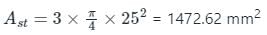
We know that,
Depth of Neutral Axis (xu):
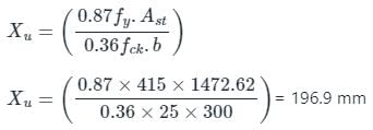
Ulyimtae MOR is given as:
Mu = 0.87 fy.Ast.(d - 0.42Xu)
Mu = 0.87×415× 1472.62 (450- 0.42 × 196.9)
Mu = 195290598.7 N-mm
Mu = 195.29 kN-m
Working MOR =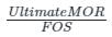
= 195.29/1.5
Working MOR = 130.19 kN-m
MOR = 0.87× fy × Ast(d - 0.42Xu)
Where, Xu = Depth of neutral axis, Ast = Area of reinforcement
Depth of neutral axis is calculated as:
Compression force = Tension force
0.36 fck b Xu = 0.87 fy Ast
Calculation:
Given,
d = 450 mm, b = 300 mm
M25 and Fe415
We know that,
Depth of Neutral Axis (xu):
Ulyimtae MOR is given as:
Mu = 0.87 fy.Ast.(d - 0.42Xu)
Mu = 0.87×415× 1472.62 (450- 0.42 × 196.9)
Mu = 195290598.7 N-mm
Mu = 195.29 kN-m
Working MOR =
= 195.29/1.5
Working MOR = 130.19 kN-m
Which of the following format is used in limit state method?- a)Single safety factor
- b)Multiple safety factor
- c)Load factor
- d)Wind factor
Correct answer is option 'B'. Can you explain this answer?
Which of the following format is used in limit state method?
a)
Single safety factor
b)
Multiple safety factor
c)
Load factor
d)
Wind factor

|
Sreemoyee Chauhan answered |
Limit State Method:
The limit state method is a design philosophy used in structural engineering to ensure the safety and serviceability of structures. It involves considering two main limit states, namely the ultimate limit state (ULS) and the serviceability limit state (SLS). The ULS addresses the structure's strength and stability under extreme loads, while the SLS focuses on the structure's performance under normal service loads.
Multiple Safety Factor:
In the limit state method, the multiple safety factor format is used. This format involves considering different design actions and applying specific safety factors to each of them. The safety factors are determined based on the reliability of the material and the level of uncertainty associated with the design action.
Design Actions:
Design actions in structural engineering refer to the loads and forces that a structure is expected to experience during its lifetime. These actions include dead loads, live loads, wind loads, earthquake loads, temperature effects, and other environmental effects.
Safety Factors:
Safety factors are used to account for uncertainties in the design process. They provide a margin of safety by multiplying the characteristic load or action with a factor that reflects the level of uncertainty. The safety factors consider factors such as material properties, workmanship, design methods, and environmental conditions.
Load Factor:
Load factor is one of the safety factors used in the multiple safety factor format. It accounts for uncertainties in the magnitude and distribution of loads. Load factors are determined based on statistical analysis and are specific to different design actions. For example, the load factors for dead loads may be different from those for live loads or wind loads.
Wind Factor:
The wind factor mentioned in the options is not directly related to the format used in the limit state method. However, wind loads are considered as one of the design actions in structural engineering, and specific load factors are applied to account for uncertainties in wind effects.
Conclusion:
In the limit state method, the multiple safety factor format is used. This format involves considering different design actions and applying specific safety factors to each of them. Load factors are used to account for uncertainties in the magnitude and distribution of loads, including dead loads, live loads, wind loads, and other environmental effects. While wind loads are a design action, the term "wind factor" is not commonly used in the context of the limit state method.
The short term deflections of prestressed members of class-1 and class-2 types under service loads are influenced by?- a)Length of prestressing force
- b)Depth of prestressing force
- c)Magnitude of prestressing force
- d)Eccentricity of prestressing force
Correct answer is option 'C'. Can you explain this answer?
The short term deflections of prestressed members of class-1 and class-2 types under service loads are influenced by?
a)
Length of prestressing force
b)
Depth of prestressing force
c)
Magnitude of prestressing force
d)
Eccentricity of prestressing force
|
|
Sanya Agarwal answered |
Short term deflections of prestressed members of class-1 and class-2 types under service loads are influenced by: magnitude of the prestressing force and its profile, applied load and self weight of the member and flexural rigidity of the Un cracked concrete sections.
The shapes of the bending moment diagram for a uniform cantilever beam carrying a uniformly distributed load over its length is- a)A straight line
- b)An ellipse
- c)A hyperbola
- d)A parabola
Correct answer is option 'D'. Can you explain this answer?
The shapes of the bending moment diagram for a uniform cantilever beam carrying a uniformly distributed load over its length is
a)
A straight line
b)
An ellipse
c)
A hyperbola
d)
A parabola
|
|
Sahana Choudhary answered |
Shape of Bending Moment Diagram for a Uniform Cantilever Beam carrying a Uniformly Distributed Load
The bending moment diagram for a beam represents how the bending moment varies along the length of the beam. In the case of a uniform cantilever beam carrying a uniformly distributed load over its length, the shape of the bending moment diagram is a parabola.
Explanation:
- A cantilever beam is a type of beam that is fixed at one end and free at the other end. It is supported only at one point, and the load is applied at the free end.
- When a uniform load is applied to a cantilever beam, it means that the load is distributed evenly over the entire length of the beam.
- The bending moment at any point along the beam is given by the equation M = w*x^2/2, where M is the bending moment, w is the uniformly distributed load per unit length, and x is the distance from the fixed end.
- As we can see from the equation, the bending moment is directly proportional to the square of the distance from the fixed end. This means that the bending moment increases quadratically as we move away from the fixed end.
- Therefore, the shape of the bending moment diagram for a uniform cantilever beam carrying a uniformly distributed load is a parabola.
- The vertex of the parabola represents the maximum bending moment, which occurs at the fixed end of the beam.
- The bending moment gradually decreases as we move towards the free end of the beam, resulting in a downward-sloping parabolic shape.
Conclusion:
In conclusion, the shape of the bending moment diagram for a uniform cantilever beam carrying a uniformly distributed load over its length is a parabola. This is because the bending moment varies quadratically with the distance from the fixed end of the beam. Understanding the shape of the bending moment diagram is important in structural analysis as it helps engineers design beams and determine the maximum bending moment and shear forces acting on the beam.
Limit State Method is based on ____- a)calculations on service load conditions alone
- b)calculations on ultimate load conditions alone
- c)calculations at working loads and ultimate loads
- d)calculations on earthquake loads
Correct answer is option 'C'. Can you explain this answer?
Limit State Method is based on ____
a)
calculations on service load conditions alone
b)
calculations on ultimate load conditions alone
c)
calculations at working loads and ultimate loads
d)
calculations on earthquake loads
|
|
Sanvi Kapoor answered |
Working stress method is based on calculations on service load conditions alone. Ultimate Strength method is based on calculations on ultimate load conditions alone. In Limit State method, safety at ultimate loads and serviceability at working loads are considered.
A beam of rectangular cross-section (b x d) is subjected to a torque T. What is the maximum torsional stress induced in the beam (b < d and α is a constant)?
- a)T/αb2d
- b)T/αbd2
- c)T/αbd
- d)T/bd
Correct answer is option 'A'. Can you explain this answer?
A beam of rectangular cross-section (b x d) is subjected to a torque T. What is the maximum torsional stress induced in the beam (b < d and α is a constant)?
a)
T/αb2d
b)
T/αbd2
c)
T/αbd
d)
T/bd
|
|
Shraddha Datta answered |
Torsion constant of a rectangular section of width b and depth d (b < d) may be expressed as,
J = b3d
J = b3d
For T, L and / sections torsion constant,

where bi and di are the dimensions of each of the component rectangles into which the section may be divided.
Torsional shear stress for rectangular section
Torsional shear stress for rectangular section

For T, L and / sections torsional shear stress may be calculated for each component rectangle by considering them subjected to torsional moment,

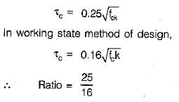
The ratio of permissible shear stress in limit state method of design and working stress method of design is- a)25 : 16
- b)5 : 4
- c)16 : 25
- d)4 : 5
Correct answer is option 'A'. Can you explain this answer?
The ratio of permissible shear stress in limit state method of design and working stress method of design is
a)
25 : 16
b)
5 : 4
c)
16 : 25
d)
4 : 5

|
Hiral Sharma answered |
Permissible shear stress.
In limit state method of design,
In limit state method of design,
Permissible stress σcb as per IS : 456 for M20 concrete is:- a)5 N/mm2
- b)8.5 N/mm2
- c)6 N/mm2
- d)7 N/mm2
Correct answer is option 'D'. Can you explain this answer?
Permissible stress σcb as per IS : 456 for M20 concrete is:
a)
5 N/mm2
b)
8.5 N/mm2
c)
6 N/mm2
d)
7 N/mm2
|
|
Devansh Banerjee answered |
Permissible stress refers to the maximum stress that a material or structural element can withstand without experiencing permanent deformation or failure. It is typically determined through various testing methods and is specified by engineering codes and standards. The permissible stress may vary depending on factors such as the type of material, the loading conditions, and the desired level of safety. It is important to ensure that the applied stress does not exceed the permissible stress to prevent structural failure or damage.
A reinforced concrete column of size 400 mm × 400 mm is having the diameter of longitudinal bar as 20 mm. The pitch of lateral ties in such a case should be:- a)320 mm
- b)400 mm
- c)300 mm
- d)250 mm
Correct answer is option 'C'. Can you explain this answer?
A reinforced concrete column of size 400 mm × 400 mm is having the diameter of longitudinal bar as 20 mm. The pitch of lateral ties in such a case should be:
a)
320 mm
b)
400 mm
c)
300 mm
d)
250 mm
|
|
Bhaskar Rane answered |
X 400 mm is subjected to a compressive load of 500 kN. The column is 3 meters in height. The concrete has a compressive strength of 30 MPa and the steel reinforcement has a yield strength of 400 MPa. Determine if the column is safe against compressive failure.
To determine if the column is safe against compressive failure, we need to calculate the maximum load the column can withstand and compare it to the applied load.
First, let's calculate the cross-sectional area of the column:
Area = (400 mm) x (400 mm) = 160,000 mm² = 0.160 m²
The maximum load the column can withstand is given by the formula:
Maximum Load = Area x Compressive Strength of Concrete
Maximum Load = 0.160 m² x 30 MPa = 4.8 MN
Now, let's compare the maximum load with the applied load:
Applied Load = 500 kN = 0.5 MN
Since the maximum load (4.8 MN) is greater than the applied load (0.5 MN), the column is safe against compressive failure.
Which of the following reservoirs is also known as ___________- a)Ground service reservoirs
- b)Elevated reservoirs
- c)Over head reservoirs
- d)Storey reservoirs
Correct answer is option 'A'. Can you explain this answer?
Which of the following reservoirs is also known as ___________
a)
Ground service reservoirs
b)
Elevated reservoirs
c)
Over head reservoirs
d)
Storey reservoirs
|
|
Sanya Agarwal answered |
Ground service reservoirs are constructed at ground level and mainly used to store water. They are generally constructed with masonry (or) RCC slab. These are also known as surface reservoirs or not elevated reservoirs.
Which of the following factors is included in the limit state of strength?- a)Fire
- b)Failure by excessive deformation
- c)Corrosion
- d)Repairable damage or crack due to fatigue
Correct answer is option 'B'. Can you explain this answer?
Which of the following factors is included in the limit state of strength?
a)
Fire
b)
Failure by excessive deformation
c)
Corrosion
d)
Repairable damage or crack due to fatigue
|
|
Tanvi Shah answered |
Limit state of strength are prescribed to avoid collapse of structure which may endanger safety of life and property. It includes (i) loss of equilibrium of whole or part of structure, (ii) loss of stability of structure as a whole or part of structure, (iii) failure by excessive deformation, (iv) fracture due to fatigue , (v) brittle fracture.
Eccentrically loaded columns have to be designed for combined axial and ________- a)Shear force
- b)Bending moments
- c)Torsion
- d)Creep
Correct answer is option 'B'. Can you explain this answer?
Eccentrically loaded columns have to be designed for combined axial and ________
a)
Shear force
b)
Bending moments
c)
Torsion
d)
Creep
|
|
Tanvi Shah answered |
When the line of action of the resultant force doesn’t coincide with the axis of centre of gravity then it is called eccentrically loaded column. An eccentrically loaded column has to be designed for combined axial force and bending moments.
As per IS 456 : 2000, using working stress method, the modular ratio of M25 grade of concrete for permissible compressive strength due to bending in concrete σcbc = 8.5 MPa is:- a)15.63
- b)10.98
- c)12.04
- d)14.39
Correct answer is option 'B'. Can you explain this answer?
As per IS 456 : 2000, using working stress method, the modular ratio of M25 grade of concrete for permissible compressive strength due to bending in concrete σcbc = 8.5 MPa is:
a)
15.63
b)
10.98
c)
12.04
d)
14.39
|
|
Aniket Mehta answered |
However, I can explain the concept of modular ratio and its formula.
Modular ratio is the ratio of the modulus of elasticity of steel to that of concrete. It is denoted by the symbol "m".
The formula for modular ratio (m) is:
m = Es / Ec
where, Es = modulus of elasticity of steel
Ec = modulus of elasticity of concrete
As per IS 456: 2000, the value of modulus of elasticity of steel (Es) is taken as 2 x 10^5 N/mm^2, and the value of modulus of elasticity of concrete (Ec) is taken as 5000 √fck N/mm^2, where fck is the characteristic compressive strength of concrete at 28 days.
For M25 grade of concrete, the characteristic compressive strength of concrete at 28 days is 25 N/mm^2.
So, the value of modulus of elasticity of concrete (Ec) for M25 grade of concrete is:
Ec = 5000 √fck
= 5000 √25
= 5000 x 5
= 25,000 N/mm^2
Therefore, the modular ratio (m) for M25 grade of concrete is:
m = Es / Ec
= 2 x 10^5 / 25,000
= 8
Hence, the modular ratio of M25 grade of concrete for permissible compressive strength due to bending in concrete is 8.
A column has a rectangular cross-section of 10 mm20 mm and a length of 1 m. The slenderness ratio of the column is close to- a)200
- b)346
- c)477
- d)1000
Correct answer is option 'B'. Can you explain this answer?
A column has a rectangular cross-section of 10 mm20 mm and a length of 1 m. The slenderness ratio of the column is close to
a)
200
b)
346
c)
477
d)
1000
|
|
Lavanya Menon answered |
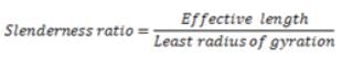
Least radius of gyration will be along the major axis
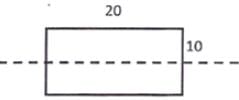
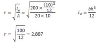
Slenderness ratio =1000/2.887=3.46
What will be the variation in BMD for the diagram? [Assume l = 2m].
- a)Rectangular
- b)Trapezoidal
- c)Triangular
- d)Square
Correct answer is option 'C'. Can you explain this answer?
What will be the variation in BMD for the diagram? [Assume l = 2m].
a)
Rectangular
b)
Trapezoidal
c)
Triangular
d)
Square

|
Pioneer Academy answered |
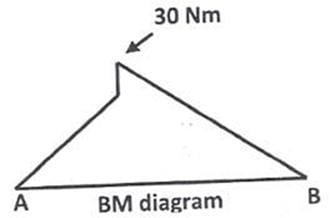
At support B, the BM is zero. The beam undergoes maximum BM at fixed end.
By joining the base line, free end and maximum BM point. We obtain a right angled triangle.
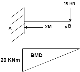
By joining the base line, free end and maximum BM point. We obtain a right angled triangle.
A short axially loaded square column 500 mm × 500 mm is subjected to service load of 2000 kN. Calculate the ultimate load and minimum area of longitudinal reinforcement as per IS 456:2000- a)1000 kN , 1250 mm2
- b)2000 kN , 2500 mm2
- c)3000 kN , 2000 mm2
- d)4000 kN , 3750 mm2
Correct answer is option 'C'. Can you explain this answer?
A short axially loaded square column 500 mm × 500 mm is subjected to service load of 2000 kN. Calculate the ultimate load and minimum area of longitudinal reinforcement as per IS 456:2000
a)
1000 kN , 1250 mm2
b)
2000 kN , 2500 mm2
c)
3000 kN , 2000 mm2
d)
4000 kN , 3750 mm2
|
|
Pallabi Tiwari answered |
Long has a cross-sectional area of 100 mm². The compressive stress in the column is 50 MPa. What is the compressive force acting on the column?
The compressive force can be calculated using the equation:
F = A x σ
Where F is the compressive force, A is the cross-sectional area of the column, and σ is the compressive stress.
Substituting the given values:
F = 100 mm² x 50 MPa
F = 5000 N
Therefore, the compressive force acting on the column is 5000 N.
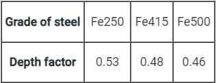
In WSM, if the critical depth of neutral axis is equal to k × d where d is effective depth of beam, then what is the value of k for steel 500 and concrete M25?- a)0.40
- b)0.48
- c)0.253
- d)0.46
Correct answer is option 'C'. Can you explain this answer?
In WSM, if the critical depth of neutral axis is equal to k × d where d is effective depth of beam, then what is the value of k for steel 500 and concrete M25?
a)
0.40
b)
0.48
c)
0.253
d)
0.46
|
|
Sanya Agarwal answered |
For the given condition:
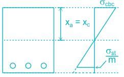
Given
Grade of Concrete = M20 , Grade of Steel = Fe500
We know
Critical depth of Neutral axis is given by:
xc = k × d
Where σst - Permissible stresses in Steel
σcbc - Permissible stresses in concrete
For Grade M25 → σcbc = 8.5 N/mm2
For Fe500 → σst = 0.55 × fy = 0.55 × 500 = 275 N/mm2
Equating in the formula
∴ xc = 0.2528 × d ≈ 0.253 × d
Comparing it with xc = k × d ⇒ k values come out to be 0.253
Important Points
For LSM Method,
As per IS 456:2000, cl.38.1
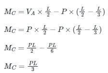
A concentrated load P acts on a simply supported beam of span L at a distance L/3 from the left support. The bending moment at the point of application of the load is given by- a)PL/3
- b)2PL/3
- c)PL/9
- d)2PL/9
Correct answer is option 'D'. Can you explain this answer?
A concentrated load P acts on a simply supported beam of span L at a distance L/3 from the left support. The bending moment at the point of application of the load is given by
a)
PL/3
b)
2PL/3
c)
PL/9
d)
2PL/9
|
|
Lavanya Menon answered |
For vertical equilibrium
R1 + R2 = P
Taking moment about R1, we have

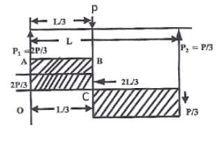
The bending moment at the point of application of load = Area under OABC
R1 + R2 = P
Taking moment about R1, we have
The bending moment at the point of application of load = Area under OABC
The minimum eccentricity to be considered for an axially loaded RCC column of size 400 mm × 400 mm with unsupported length of 5 m is:- a)15.6 mm
- b)20.5 mm
- c)23.3 mm
- d)30.6 mm
Correct answer is option 'C'. Can you explain this answer?
The minimum eccentricity to be considered for an axially loaded RCC column of size 400 mm × 400 mm with unsupported length of 5 m is:
a)
15.6 mm
b)
20.5 mm
c)
23.3 mm
d)
30.6 mm
|
|
Sravya Tiwari answered |
The minimum eccentricity to be considered for an axially loaded RCC column of size 400 mm would depend on the design requirements and the specific code or standards being used.
In general, the eccentricity is the distance between the centroid of the column section and the line of action of the applied axial load. It is important to consider eccentricity in the design of RCC columns as it can lead to additional bending moments and shear forces, which can affect the structural behavior and stability of the column.
The specific minimum eccentricity requirement would depend on factors such as the column slenderness, the type of loading (e.g., concentric or eccentric), and the desired level of safety and performance.
In most design codes, there are guidelines and provisions for determining the minimum eccentricity for various column configurations and loading conditions. These provisions usually consider factors such as the column dimensions, the material properties, and the desired level of safety.
Therefore, without specific design requirements or code references, it is not possible to provide an exact value for the minimum eccentricity for a 400 mm RCC column. It would be necessary to refer to the relevant design code or consult with a structural engineer to determine the appropriate minimum eccentricity for the specific design scenario.
The following should be arranged in ascending order based on their safety factor in the working stress method: (i) Connections, (ii) Short column, (iii) Long column, (iv) Tension members- a)i < ii < iii < iv
- b)i < iv < ii < iii
- c)iv = ii < iii < i
- d)iv = i < iii < ii
Correct answer is option 'C'. Can you explain this answer?
The following should be arranged in ascending order based on their safety factor in the working stress method: (i) Connections, (ii) Short column, (iii) Long column, (iv) Tension members
a)
i < ii < iii < iv
b)
i < iv < ii < iii
c)
iv = ii < iii < i
d)
iv = i < iii < ii
|
|
Akash Mukherjee answered |
(i) Connections
(iv) Tension members
(ii) Short column
(iii) Long column
(iv) Tension members
(ii) Short column
(iii) Long column
What does the slope of a bending moment curve as a function of distance represent?- a)The load applied
- b)The stiffness at that location
- c)The deflection
- d)The shear force at that section
Correct answer is option 'D'. Can you explain this answer?
What does the slope of a bending moment curve as a function of distance represent?
a)
The load applied
b)
The stiffness at that location
c)
The deflection
d)
The shear force at that section

|
Asha Deshpande answered |
The slope of a bending moment curve as a function of distance represents the shear force at that section. To understand why, let's first define what a bending moment curve is.
A bending moment curve is a graphical representation of the variation in bending moment along the length of a beam or structural member. It is typically plotted as a function of distance along the beam. The bending moment is the internal moment that causes a beam to bend, and it is a result of external loads applied to the beam.
Now, let's discuss why the slope of the bending moment curve represents the shear force at that section.
1. Definition of Shear Force:
Shear force is the internal force within a beam that acts parallel to the cross-section of the beam. It is caused by external loads applied perpendicular to the axis of the beam.
2. Relationship between Bending Moment and Shear Force:
There is a direct relationship between the bending moment and the shear force in a beam. The bending moment at any section of a beam is equal to the rate of change of the shear force with respect to the distance along the beam.
Mathematically, this relationship can be expressed as follows:
M = dV/dx
Where:
M = Bending moment at a section
V = Shear force at that section
x = Distance along the beam
3. Analyzing the Slope of the Bending Moment Curve:
The slope of the bending moment curve represents the rate of change of the bending moment with respect to the distance along the beam. In other words, it represents the change in bending moment per unit distance.
Since the bending moment is equal to the rate of change of the shear force, the slope of the bending moment curve represents the rate of change of the shear force. Therefore, the slope of the bending moment curve at any section represents the shear force at that section.
By analyzing the slope of the bending moment curve, we can determine the magnitude and direction of the shear force at different sections of a beam. The slope will be positive when the shear force is increasing in the positive direction, and negative when the shear force is decreasing in the positive direction.
In conclusion, the slope of a bending moment curve as a function of distance represents the shear force at that section. It provides valuable information about the internal forces within a beam and is essential for analyzing the structural behavior and designing safe and efficient structures.
How many parts does IS code 875 contain?- a)5
- b)6
- c)7
- d)8
Correct answer is option 'A'. Can you explain this answer?
How many parts does IS code 875 contain?
a)
5
b)
6
c)
7
d)
8
|
|
Lavanya Menon answered |
IS 875 has five parts which address the imposed, dead, wind, snow and special loads except earthquake that act on structures.
IS 1893-2002 gives details on:- a)Seismic strengthening
- b)Improving earthquake resistance
- c)Earthquake resistance structures
- d)Earthquake resistance design
Correct answer is option 'C'. Can you explain this answer?
IS 1893-2002 gives details on:
a)
Seismic strengthening
b)
Improving earthquake resistance
c)
Earthquake resistance structures
d)
Earthquake resistance design
|
|
Tanvi Shah answered |
IS 1893-2002 gives the criteria for earthquake resistance design of structures. It is the fifth revised edition.
What is girt?- a)vertical beam spanning between wall column of industrial buildings
- b)horizontal beam spanning between wall column of industrial buildings
- c)vertical beam spanning between wall column of residential buildings
- d)horizontal beam spanning between wall column of residential buildings
Correct answer is option 'B'. Can you explain this answer?
What is girt?
a)
vertical beam spanning between wall column of industrial buildings
b)
horizontal beam spanning between wall column of industrial buildings
c)
vertical beam spanning between wall column of residential buildings
d)
horizontal beam spanning between wall column of residential buildings
|
|
Lavanya Menon answered |
Girt is horizontal member fastened to and spanning between peripheral column of industrial buildings. It is used to support wall cladding such as corrugated metal sheet.
The permissible deflections vary from a maximum of ____________- a)Span/180
- b)Span/100
- c)Span/160
- d)Span/40
Correct answer is option 'A'. Can you explain this answer?
The permissible deflections vary from a maximum of ____________
a)
Span/180
b)
Span/100
c)
Span/160
d)
Span/40
|
|
Sanya Agarwal answered |
According to the American code ACI: 318-1989, the permissible deflection vary from a maximum of span/180 to a minimum of span/480 depending upon the type of member and the seriousness of damage to the adjoining structural element.
Which IS code gives specifications about dimensions for hot rolled steel structures?- a)IS 808-1979
- b)IS 806-1968
- c)IS 806-1969
- d)IS 808-1989
Correct answer is option 'D'. Can you explain this answer?
Which IS code gives specifications about dimensions for hot rolled steel structures?
a)
IS 808-1979
b)
IS 806-1968
c)
IS 806-1969
d)
IS 808-1989
|
|
Tanvi Shah answered |
IS 808-1989 gives guidelines on dimensioning of hot rolled steel beams, columns, channel and angle sections.
Steel Beam theory is the method used to analyze and in the design of a:- a)Singly reinforced sections
- b)Both singly & double reinforced section
- c)Double reinforced sections
- d)Column structures only
Correct answer is option 'C'. Can you explain this answer?
Steel Beam theory is the method used to analyze and in the design of a:
a)
Singly reinforced sections
b)
Both singly & double reinforced section
c)
Double reinforced sections
d)
Column structures only
|
|
Sanya Agarwal answered |
Steel beam theory is used to find the approximate value of the moment of resistance of a doubly reinforced beam specially when the area of compression steel is equal to or more than the area of the tensile steel.
In this theory, we assume concrete is weak in compression also then we get same amount of steel in both tension & compression, hence all the moment will be resisted by steel only and concrete will be of no use.
In the steel beam theory :
(i) Concrete is completely neglected.
(ii) The moment of resistance is taken equal to the amount of the couple of compressive and tensile steel.
(iii) The permissible stress in compressive steel is taken as equal to the permissible stress in tensile steel.
Permissible stress σcb as per IS : 456 for M20 concrete is:- a)5 N/mm2
- b)7 N/mm2
- c)6 N/mm2
- d)4 N/mm2
Correct answer is option 'B'. Can you explain this answer?
Permissible stress σcb as per IS : 456 for M20 concrete is:
a)
5 N/mm2
b)
7 N/mm2
c)
6 N/mm2
d)
4 N/mm2
|
|
Rithika Kaur answered |
Permissible Stress σcb for M20 concrete as per IS : 456
Permissible stress σcb as per IS : 456 for M20 concrete is 7 N/mm2.
Explanation:
- IS : 456 Code: IS : 456 is the Indian Standard code for the design and construction of reinforced concrete structures.
- M20 Concrete Grade: M20 concrete is a mix design where the nominal mix ratio of cement, sand, and aggregate is 1:1.5:3.
- Permissible Stress: According to IS : 456, the permissible stress for concrete in bending compression is denoted as σcb.
- Permissible Stress for M20 concrete: The permissible stress σcb for M20 concrete is 7 N/mm2. This means that the maximum stress that can be applied to M20 concrete in bending compression is 7 N/mm2.
- Importance of Permissible Stress: Adhering to the permissible stress limits ensures the safety and durability of the structure. Exceeding the permissible stress can lead to structural failure and compromise the safety of the building.
Therefore, the permissible stress σcb for M20 concrete as per IS : 456 is 7 N/mm2. It is essential to follow these guidelines to ensure the structural integrity of the building.
The contribution of bent up bars towards shear resistance shall not be more than- a)50% of total shear reinforcement
- b)40% of total shear reinforcement
- c)55% of total shear reinforcement
- d)30% of total shear reinforcement
Correct answer is option 'A'. Can you explain this answer?
The contribution of bent up bars towards shear resistance shall not be more than
a)
50% of total shear reinforcement
b)
40% of total shear reinforcement
c)
55% of total shear reinforcement
d)
30% of total shear reinforcement
|
|
Baishali Chopra answered |
Total shear strength = shear resistance of effective concrete area as a function of longitudinal bars + shear resistance of vertical shear stirrups + shear resistance of-inclined shear stirrups.
Tests have shown that inclined bars alone do not provide a satisfactory solution and their contribution is limited to 50% of net shear strength after deducting the contribution of concrete. The remaining shear resistance is provided by vertical stirrups.
Tests have shown that inclined bars alone do not provide a satisfactory solution and their contribution is limited to 50% of net shear strength after deducting the contribution of concrete. The remaining shear resistance is provided by vertical stirrups.
Maximum stress in concrete by code is restricted to ______.- a)0.67fck
- b)0.447fck
- c)0.87fck
- d)0.53fck
Correct answer is option 'A'. Can you explain this answer?
Maximum stress in concrete by code is restricted to ______.
a)
0.67fck
b)
0.447fck
c)
0.87fck
d)
0.53fck
|
|
Manasa Bose answered |
Maximum Stress in Concrete by Code:
Code provisions are established to ensure the safety of structures. The maximum allowable stress in concrete is one of the important provisions. The maximum stress in concrete by code is restricted to 0.67fck.
Explanation:
- The maximum allowable compressive stress in concrete is governed by the strength of concrete. The strength of concrete is usually denoted by the characteristic compressive strength of concrete, fck.
- As per the Indian Standard Code of Practice for Plain and Reinforced Concrete, IS 456:2000, the maximum allowable compressive stress in concrete is 0.67fck. This is based on the assumption that the concrete is homogenous and isotropic.
- The maximum allowable compressive stress in concrete is restricted to 0.67fck to ensure the safety of the structure. If the stress exceeds this limit, it may lead to the failure of the structure.
- The factor of safety is also considered while designing the structure. The factor of safety is the ratio of the ultimate strength of the structure to the working stress. The factor of safety is usually taken as 1.5 to 2.5 depending upon the type of structure and loading conditions.
- The maximum allowable stress in concrete is also influenced by other factors such as age of concrete, curing conditions, and the type of aggregate used.
Conclusion:
In conclusion, the maximum stress in concrete by code is restricted to 0.67fck to ensure the safety of the structure. This provision is based on the assumption that the concrete is homogenous and isotropic. Other factors such as age of concrete, curing conditions, and the type of aggregate used also influence the maximum allowable stress in concrete.
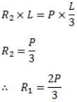
A simply supported beam of span L is subjected to two point loads, each of magnitude P, acting at one third of the span, as shown in the figure below. Which of the follloing statements is correct about the nature of the BMD?
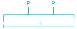
- a)Bending moment is zero at the mid span section.
- b)Bending moment first increases linearly up to mid span then decreases linearly in the middle one third part.
- c)Bending moment is constant in the middle one third part
- d)Bending moment is constant in the left one third part
Correct answer is option 'C'. Can you explain this answer?
A simply supported beam of span L is subjected to two point loads, each of magnitude P, acting at one third of the span, as shown in the figure below. Which of the follloing statements is correct about the nature of the BMD?
a)
Bending moment is zero at the mid span section.
b)
Bending moment first increases linearly up to mid span then decreases linearly in the middle one third part.
c)
Bending moment is constant in the middle one third part
d)
Bending moment is constant in the left one third part
|
|
Pioneer Academy answered |
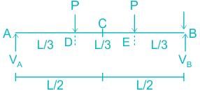
The point loads are applied symmetrically to the simply supported beam with respect to mid-span (or point C), so the vertical reaction at both supports is equal and is half the applied load.
VA = VB = P
Calculating the bending moment at point D

Calculating the bending moment at point C
The bending moment at points A and B is zero because supports A and B are simply supports (roller and hinge).

Hence the bending moment is constant in the middle one-third part of the beam.
For a reinforced concrete section, the shape of shear stress diagram is- a)wholly parabolic
- b)wholly rectangular
- c)Parabolic above neutral axis and rectangular below neutral axis
- d)rectangular above neutral axis and parabolic below neutral axis
Correct answer is option 'C'. Can you explain this answer?
For a reinforced concrete section, the shape of shear stress diagram is
a)
wholly parabolic
b)
wholly rectangular
c)
Parabolic above neutral axis and rectangular below neutral axis
d)
rectangular above neutral axis and parabolic below neutral axis
|
|
Samridhi Choudhary answered |

What is the minimum area of tension reinforcement in beams when Fe 415 is used?- a)0.8%
- b)0.12%
- c)0.15%
- d)0.2%
Correct answer is option 'D'. Can you explain this answer?
What is the minimum area of tension reinforcement in beams when Fe 415 is used?
a)
0.8%
b)
0.12%
c)
0.15%
d)
0.2%
|
|
Rahul Chauhan answered |
Tension reinforcement in beams:
In reinforced concrete beams, tension reinforcement is provided to resist the tensile forces that develop due to bending. The minimum area of tension reinforcement is determined based on the grade of steel used.
Fe 415 steel:
Fe 415 is a common grade of steel used in reinforced concrete structures. The number '415' refers to the minimum yield strength of the steel in megapascals (MPa). Fe 415 steel has a yield strength of 415 MPa.
Minimum area of tension reinforcement:
The minimum area of tension reinforcement in beams is specified by design codes and standards. In the case of Fe 415 steel, the minimum area of tension reinforcement is 0.2% of the gross cross-sectional area of the beam.
Explanation:
The minimum area of tension reinforcement is specified to ensure adequate strength and ductility of the beam. The tension reinforcement helps to control cracking and prevent sudden failure of the beam.
The 0.2% value represents the proportion of the cross-sectional area of the beam that needs to be provided as tension reinforcement. For example, if the cross-sectional area of a beam is 1 square meter, the minimum area of tension reinforcement required would be 0.2% of 1 square meter, which is 0.002 square meters or 200 square centimeters.
By providing the minimum area of tension reinforcement, the beam can effectively resist the tensile forces that develop due to bending. This ensures the overall stability and safety of the structure.
It is important to note that the minimum area of tension reinforcement is a design requirement and should be followed to ensure the structural integrity of the beam. However, additional reinforcement may be provided based on the specific design requirements and load conditions.
In conclusion, the minimum area of tension reinforcement in beams when Fe 415 is used is 0.2% of the gross cross-sectional area of the beam.
At what height from the base of a pillar must the end of a rope of length l be fixed so that a man standing on the ground and pulling it at the other end may have the greatest tendency to overturn the pillar- a)l/2
- b)2l/3
- c)l/√2
- d)2
Correct answer is option 'C'. Can you explain this answer?
At what height from the base of a pillar must the end of a rope of length l be fixed so that a man standing on the ground and pulling it at the other end may have the greatest tendency to overturn the pillar
a)
l/2
b)
2l/3
c)
l/√2
d)
2
|
|
Tanvi Shah answered |
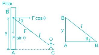
The pillar will have the greatest tendency of overturning when the Moment of the force F induced in the rope will have a maximum moment about the base of the pillar A.
Hence, To find the greatest overturning tendency, we have to maximise MA.
Calculation:
Given,
Length of the rope = l,
let y = height from the ground at which rope is fixed to the pillar.
Taking moment about A we get,
MA = F × cos θ × y
From ΔABC, y = l × sin θ
MA = Fl × cos θ × sin θ = Fl/2 x sin2θ
For the maximum value of MA, sin 2θ = 90° , θ = 45 °
y = l × sin θ y = l × sin 45° = l/√ 2
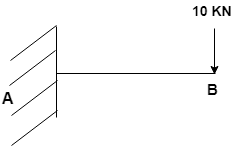
What is the maximum shear force, when a cantilever beam is loaded with udl throughout?- a)w×l
- b)w
- c)w/l
- d)w+l
Correct answer is option 'A'. Can you explain this answer?
What is the maximum shear force, when a cantilever beam is loaded with udl throughout?
a)
w×l
b)
w
c)
w/l
d)
w+l
|
|
Lavanya Menon answered |
In cantilever beams, the maximum shear force occurs at the fixed end. In the free end, there is zero shear force. As we need to convert the udl in to load, we multiply the length of the cantilever beam with udl acting upon. For maximum shear force to obtain we ought to multiply load and distance and it surely occurs at the fixed end (w×l).
Which IS code is used to refer details regarding measurement of building and civil engineering works?- a)IS 1200
- b)IS 2502
- c)IS 1786
- d)IS 800
Correct answer is option 'A'. Can you explain this answer?
Which IS code is used to refer details regarding measurement of building and civil engineering works?
a)
IS 1200
b)
IS 2502
c)
IS 1786
d)
IS 800
|
|
Sakshi Basak answered |
Introduction:
In the field of civil engineering and construction, accurate measurement of building and civil engineering works is crucial for ensuring the quality and cost-effectiveness of projects. To provide standardized guidelines and specifications for measurement, the Bureau of Indian Standards (BIS) has developed a comprehensive set of codes known as the Indian Standards (IS). These codes cover various aspects of construction and engineering, including measurement and quantification of materials and works.
IS 1200 - Method of Measurement of Building and Civil Engineering Works:
One such important code is IS 1200, which provides detailed guidelines for the measurement of building and civil engineering works. It outlines the standardized procedures and rules to be followed during the measurement process to ensure consistency and accuracy across different projects.
Key Points of IS 1200:
1. Scope: IS 1200 covers the measurement of different types of works including buildings, roads, bridges, dams, water supply and drainage systems, etc. It provides guidelines for both manual and computerized methods of measurement.
2. Units and Conversions: The code specifies the units of measurement to be used for different types of works. It also provides conversion factors for converting between different units, ensuring uniformity in measurement across projects.
3. Measurement Rules: IS 1200 outlines the rules and procedures to be followed during measurement, including the order of measurement, rounding off of values, exclusion of voids, etc. These rules help in minimizing errors and ensuring consistency in measurement.
4. Measurement of Different Items: The code provides detailed guidelines for the measurement of various items such as excavation, concrete work, brickwork, plastering, flooring, roofing, painting, etc. It specifies the measurement methods, formulas, and factors to be considered for each item.
5. Bill of Quantities: IS 1200 also includes provisions for the preparation of a bill of quantities, which is a detailed document specifying the quantities of different items of work required for a project. The bill of quantities serves as the basis for cost estimation, tendering, and contract administration.
6. Quality Control: The code emphasizes the importance of quality control during measurement and provides guidelines for checking the accuracy and completeness of measurements.
Conclusion:
IS 1200 is a crucial code in civil engineering that provides standardized guidelines for the measurement of building and civil engineering works. By following the procedures and rules outlined in this code, engineers and construction professionals can ensure accurate measurement, cost-effective project management, and quality control.
What is beam?- a)structural member subjected to transverse loads
- b)structural member subjected to axial loads only
- c)structural member subjected to seismic loads only
- d)structural member subjected to transverse loads only
Correct answer is option 'A'. Can you explain this answer?
What is beam?
a)
structural member subjected to transverse loads
b)
structural member subjected to axial loads only
c)
structural member subjected to seismic loads only
d)
structural member subjected to transverse loads only
|
|
Milan Ghosh answered |
**Beam: A Structural Member Subjected to Transverse Loads**
A beam is a crucial structural element used in various construction projects. It is a horizontal or near-horizontal member that is designed to support transverse loads, such as the weight of the structure above it or the forces imposed on it from various sources. Beams are commonly used in buildings, bridges, and other structures to provide support and help distribute loads.
**Explanation:**
1. **Definition of a Beam:**
- A beam is a structural member that is primarily designed to resist transverse loads.
- Transverse loads refer to the loads that act perpendicular to the longitudinal axis of the beam.
- These loads can include the weight of the structure, live loads (such as people or vehicles), wind forces, and other external forces.
2. **Types of Loads on a Beam:**
- Beams are subjected to various types of loads.
- Transverse loads are the primary loads that act perpendicular to the longitudinal axis of the beam.
- Axial loads, on the other hand, act along the longitudinal axis of the beam.
- Seismic loads are dynamic loads generated by earthquakes or ground vibrations.
3. **Beam Behavior under Transverse Loads:**
- When a beam is subjected to transverse loads, it experiences bending.
- Bending causes the beam to undergo deformation, resulting in both tension and compression forces within the beam.
- The top fibers of the beam experience compression, while the bottom fibers experience tension.
- These forces create internal stresses within the beam that must be carefully analyzed and accounted for during the design process.
4. **Design Considerations for Beams:**
- Beams are designed to ensure that they can safely carry the anticipated loads without failure.
- The design process involves calculating the internal stresses and deflection of the beam based on the applied loads.
- Engineers use various design methods, such as the Euler-Bernoulli beam theory and the moment-area method, to determine the structural requirements of the beam.
- The size, shape, and material of the beam are also considered to ensure adequate strength and stiffness.
In conclusion, a beam is a structural member that is primarily subjected to transverse loads. These loads act perpendicular to the longitudinal axis of the beam and cause bending, resulting in tension and compression forces. Designing beams to withstand these transverse loads is essential for ensuring the structural integrity and safety of buildings and other structures.
IS 2062 gives specifications about:- a)High strength steel
- b)High strength concrete
- c)Concrete for general purpose
- d)Steel for general purpose
Correct answer is option 'D'. Can you explain this answer?
IS 2062 gives specifications about:
a)
High strength steel
b)
High strength concrete
c)
Concrete for general purpose
d)
Steel for general purpose
|
|
Sanya Agarwal answered |
IS 2062 gives the specifications for steel to be used for general purposes.
The primary serviceability limit state corresponds to excessive ____________- a)Compression and tension
- b)Deflection and cracking
- c)Shear and Friction
- d)Torsion and mass
Correct answer is option 'B'. Can you explain this answer?
The primary serviceability limit state corresponds to excessive ____________
a)
Compression and tension
b)
Deflection and cracking
c)
Shear and Friction
d)
Torsion and mass
|
|
Sanya Agarwal answered |
Serviceability limit state corresponds to excessive deflection and cracking and it is customary in most codes to safeguard against excessive deflection under serviceability limit state, either indirectly by prescribing minimum span/depth ratio for the member or directly specifying a maximum permissible deflection expressed as a fraction of the span.
A concentrated load P acts on a simply supported beam of span L at a distance L/3 from the left support. The bending moment at the point of application of the load is given by- a)PL/3
- b)2PL/3
- c)PL/9
- d)2PL/9
Correct answer is option 'D'. Can you explain this answer?
A concentrated load P acts on a simply supported beam of span L at a distance L/3 from the left support. The bending moment at the point of application of the load is given by
a)
PL/3
b)
2PL/3
c)
PL/9
d)
2PL/9
|
|
Lavanya Menon answered |
For vertical equilibrium

Taking moment about R1 , we have
Taking moment about R1 , we have
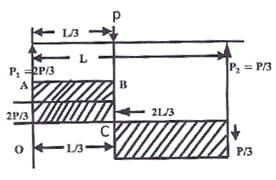
The bending moment at the point of application of load =Area under OABC
Select the CORRECT name of the column among the given options that should have the ratio of effective length to its least lateral dimension more than 12.- a)Long column
- b)Pedestal
- c)Short column
- d)Plastic column
Correct answer is option 'A'. Can you explain this answer?
Select the CORRECT name of the column among the given options that should have the ratio of effective length to its least lateral dimension more than 12.
a)
Long column
b)
Pedestal
c)
Short column
d)
Plastic column
|
|
Tanvi Shah answered |
Slender column: Cross sections in which the elements buckle locally even before the attainment of yield stress are called slender sections.
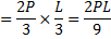
The column is classified based on its slenderness ratio.
Considering the x-axis is as major axis because Ixx is greater and the y-axis as the minor axis
a > b ⇒ Ixx > Iyy
Slenderness ratio
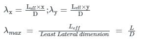
So,
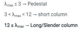
The column is classified based on its slenderness ratio.
Considering the x-axis is as major axis because Ixx is greater and the y-axis as the minor axis
a > b ⇒ Ixx > Iyy
Slenderness ratio
So,


The ends of ________ shall be properly anchored.- a)Longitudinal reinforcement
- b)Transverse reinforcement
- c)Torsional reinforcement
- d)Shear reinforcement
Correct answer is option 'B'. Can you explain this answer?
The ends of ________ shall be properly anchored.
a)
Longitudinal reinforcement
b)
Transverse reinforcement
c)
Torsional reinforcement
d)
Shear reinforcement

|
Sameer Verma answered |
Anchoring of Transverse Reinforcement in Civil Engineering
In civil engineering, the anchoring of transverse reinforcement is of utmost importance to ensure the structural integrity and stability of reinforced concrete elements. Transverse reinforcement, also known as lateral reinforcement or shear reinforcement, is used to enhance the shear capacity and ductility of concrete structures, such as beams, columns, and slabs. The ends of transverse reinforcement must be properly anchored to effectively transfer the shear forces and prevent the reinforcement from slipping or pulling out.
Importance of Anchoring Transverse Reinforcement
Anchoring the ends of transverse reinforcement provides several benefits and ensures the overall performance of the reinforced concrete element. Some of these benefits include:
1. Shear Capacity: Anchoring transverse reinforcement helps in achieving the desired shear capacity of the structural member. It improves the ability of the reinforcement to resist the shearing forces caused by the applied loads.
2. Crack Control: Proper anchoring of transverse reinforcement helps in controlling cracks that may develop due to shear stresses. By preventing the reinforcement from slipping, it ensures that the cracks are narrow and tightly closed.
3. Ductility: Anchoring transverse reinforcement enhances the ductility of concrete elements. Ductility refers to the ability of a material to deform plastically without losing its load-carrying capacity. Anchored reinforcement allows for controlled deformation and energy dissipation, thereby increasing the overall ductility of the structure.
Methods of Anchoring Transverse Reinforcement
There are various methods used to anchor transverse reinforcement, depending on the specific design requirements and structural elements. Some commonly used methods include:
1. Standard Hooks: The ends of transverse reinforcement can be provided with standard hooks, which are formed by bending the reinforcement bar at a specified angle. The hooked ends are then embedded into the concrete cover to resist the shear forces.
2. Closed Stirrups: Closed stirrups are formed by bending the transverse reinforcement into a closed loop. The closed ends of the stirrups are anchored into the concrete cover to provide effective shear transfer.
3. Mechanical Anchors: Mechanical anchors, such as anchor bolts or mechanical couplers, can also be used to anchor transverse reinforcement. These devices provide a secure connection between the reinforcement and the concrete, ensuring proper shear transfer.
Conclusion
In conclusion, the anchoring of transverse reinforcement is crucial for the proper functioning and performance of reinforced concrete elements. It ensures the shear capacity, crack control, and ductility of the structural members. Various methods, such as standard hooks, closed stirrups, and mechanical anchors, can be used to achieve effective anchorage. By properly anchoring the ends of transverse reinforcement, engineers can ensure the safety and durability of concrete structures.
A uniformly loaded propped cantilever beam and its free body diagram are shown below. The reaction are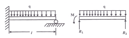
- a)

- b)

- c)

- d)

Correct answer is option 'A'. Can you explain this answer?
A uniformly loaded propped cantilever beam and its free body diagram are shown below. The reaction are
a)
b)
c)
d)

|
Vertex Academy answered |
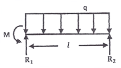
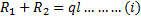
Moment about (1),
Moment about (2),
From (i), (ii), (iii), we get

Which method assumes that the structural material behaves in a linearly elastic manner?- a)None of the given options
- b)Ultimate load method
- c)Limit state method
- d)Working stress method
Correct answer is option 'D'. Can you explain this answer?
Which method assumes that the structural material behaves in a linearly elastic manner?
a)
None of the given options
b)
Ultimate load method
c)
Limit state method
d)
Working stress method
|
|
Sanvi Kapoor answered |
The design methods of reinforced cement concrete structures are as follows:
- Working stress method
- This method is based upon linear elastic theory or depends on the classical elastic theory.
- This method ensured adequate safety by suitably restricting the stress in the materials induced by the expected working leads on the structures.
- The basic assumption of linear elastic behavior is considered justifiable since the specified permissible stresses are kept well below the ultimate strength of the material.
- The ratio of the yield stress of the steel reinforcement or the concrete cube strength to the corresponding permissible or working stress value is usually called a factor of safety.
- Ultimate load method:
- This method is based on the ultimate strength of reinforced concrete at ultimate load is obtained by enhancing the service load by some factor called load factor for giving a desired margin of safety. Hence the method is also referred to as the load factor method or the ultimate strength method.
- In the ULM, the stress condition at the state of in pending collapse of the structure is analyzed, thus using, the non-linear stress-strain curves of concrete and steel.
- The safety measure in the design is obtained by the use of the proper load factor.
- Limit state method:
- Limit states are the acceptable limits for the safety and serviceability requirements of the structure before failure occurs.
- The design of structures by this method will thus ensure that they will not reach limit states and will not become unfit for the use for which they are intended.
- It is worth mentioning that structures will not just fail or collapse by violating (exceeding) the limit states. Failure, therefore, implies that clearly defined limit states of structural usefulness have been exceeded.
- Limit states are two types
- Limit state of collapse
- Limit state of serviceability
Kani’s method:
It is the method of structural analysis and its displacement method.
It is the method of structural analysis and its displacement method.
If the permissible stress in steel in tension is 140 N / mm2, then the depth of neutral axis for a single reinforced rectangular balanced section will be - a)0.45d
- b)0.30d
- c)0.40d
- d)0.35d
Correct answer is option 'C'. Can you explain this answer?
If the permissible stress in steel in tension is 140 N / mm2, then the depth of neutral axis for a single reinforced rectangular balanced section will be
a)
0.45d
b)
0.30d
c)
0.40d
d)
0.35d
|
|
Sanvi Kapoor answered |
A balanced section is one in which the area of tension steel is such that the failure of both concrete and steel occurs simultaneously.
For WSM method:
The critical depth of the neutral axis is given by –
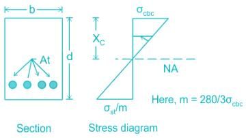
From stress distribution diagram,
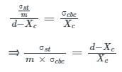
Where, Xc = kd (k = Neutral axis depth factor for balanced section)
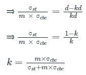
Put the value of modular ratio,
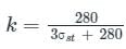
Thus the neutral axis factor for the balanced section depends only on σst and is independent of σcbc.
Calculation:
σst = 140 N / mm2
Neutral axis depth factor for balanced section
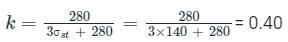
Hence, the depth of neutral axis for a single reinforced rectangular balanced section is 0.40d.
For WSM method:
The critical depth of the neutral axis is given by –
From stress distribution diagram,
Where, Xc = kd (k = Neutral axis depth factor for balanced section)
Put the value of modular ratio,
Thus the neutral axis factor for the balanced section depends only on σst and is independent of σcbc.
Calculation:
σst = 140 N / mm2
Neutral axis depth factor for balanced section
Hence, the depth of neutral axis for a single reinforced rectangular balanced section is 0.40d.
Chapter doubts & questions for Limit State & Working Stress Methods - RCC & Prestressed Concrete 2025 is part of Civil Engineering (CE) exam preparation. The chapters have been prepared according to the Civil Engineering (CE) exam syllabus. The Chapter doubts & questions, notes, tests & MCQs are made for Civil Engineering (CE) 2025 Exam. Find important definitions, questions, notes, meanings, examples, exercises, MCQs and online tests here.
Chapter doubts & questions of Limit State & Working Stress Methods - RCC & Prestressed Concrete in English & Hindi are available as part of Civil Engineering (CE) exam.
Download more important topics, notes, lectures and mock test series for Civil Engineering (CE) Exam by signing up for free.
RCC & Prestressed Concrete
13 videos|42 docs|34 tests
|

Signup to see your scores go up within 7 days!
Study with 1000+ FREE Docs, Videos & Tests
10M+ students study on EduRev
|
© EduRev
|
Education Revolution
|


|


Signup to see your scores
go up within 7 days!
Access 1000+ FREE Docs, Videos and Tests
Takes less than 10 seconds to signup